2016 BMW M4 CONVERTIBLE lane assist
[x] Cancel search: lane assistPage 18 of 226

CockpitVehicle features and options
This chapter describes all standard, country-
specific and optional features offered with the
series. It also describes features that are not
necessarily available in your car, e. g., due tothe selected options or country versions. This
also applies to safety-related functions and
systems. The respectively applicable country
provisions must be observed when using the
respective features and systems.
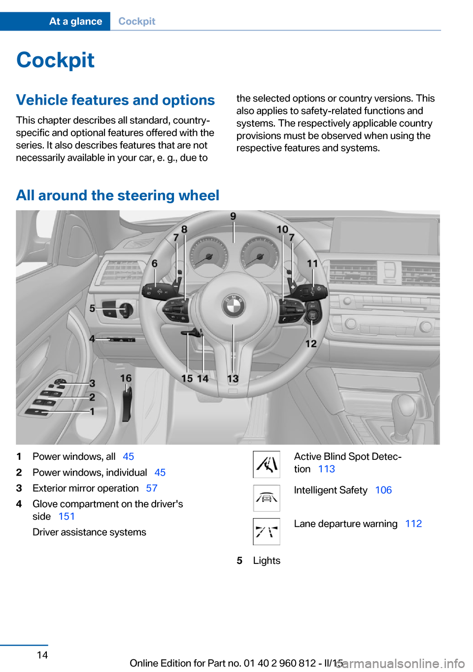
All around the steering wheel
1Power windows, all 452Power windows, individual 453Exterior mirror operation 574Glove compartment on the driver's
side 151
Driver assistance systemsActive Blind Spot Detec‐
tion 113Intelligent Safety 106Lane departure warning 1125LightsSeite 14At a glanceCockpit14
Online Edition for Part no. 01 40 2 960 812 - II/15
Page 84 of 226

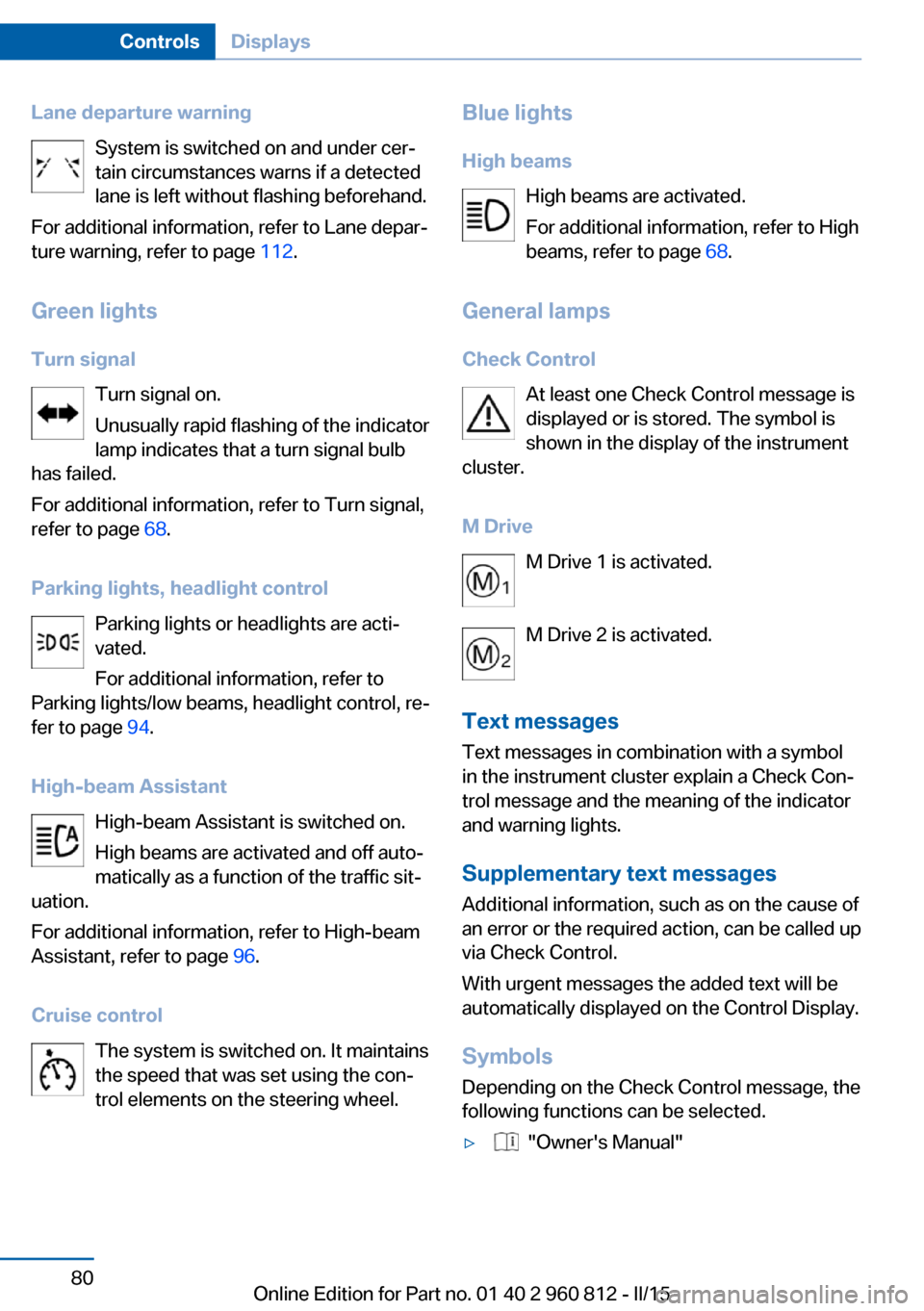
Lane departure warningSystem is switched on and under cer‐
tain circumstances warns if a detected
lane is left without flashing beforehand.
For additional information, refer to Lane depar‐
ture warning, refer to page 112.
Green lights Turn signal Turn signal on.
Unusually rapid flashing of the indicator
lamp indicates that a turn signal bulb
has failed.
For additional information, refer to Turn signal,
refer to page 68.
Parking lights, headlight control Parking lights or headlights are acti‐
vated.
For additional information, refer to
Parking lights/low beams, headlight control, re‐
fer to page 94.
High-beam Assistant High-beam Assistant is switched on.
High beams are activated and off auto‐
matically as a function of the traffic sit‐
uation.
For additional information, refer to High-beam
Assistant, refer to page 96.
Cruise control The system is switched on. It maintains
the speed that was set using the con‐
trol elements on the steering wheel.Blue lights
High beams High beams are activated.
For additional information, refer to High
beams, refer to page 68.
General lamps Check Control At least one Check Control message is
displayed or is stored. The symbol is
shown in the display of the instrument
cluster.
M Drive M Drive 1 is activated.
M Drive 2 is activated.
Text messages
Text messages in combination with a symbol
in the instrument cluster explain a Check Con‐
trol message and the meaning of the indicator
and warning lights.
Supplementary text messages
Additional information, such as on the cause of
an error or the required action, can be called up via Check Control.
With urgent messages the added text will be
automatically displayed on the Control Display.
Symbols
Depending on the Check Control message, the
following functions can be selected.▷ "Owner's Manual"Seite 80ControlsDisplays80
Online Edition for Part no. 01 40 2 960 812 - II/15
Page 119 of 226

Brake force display
The concept▷During normal brake application, the outer
brake lights light up.▷During heavy brake application, the inner
brake lights light up in addition.
Attentiveness assistant
The concept The system can detect increasing lack of alert‐
ness or fatigue of the driver during long, mo‐
notonous journeys, e.g., on highways. In this
situation, it is recommended that the driver
takes a break.
Note Personal responsibility
The system cannot act as a substitute for
the personal assessment of one's physical
state and may not detect an increasing lack of
alertness or fatigue or may not detect it cor‐
rectly. Therefore, make sure that the driver is
rested and alert; otherwise, risks may be de‐
tected too late and an accident be caused as a
result.◀
Function
The system is activated each time the engine
is started and cannot be switched off.
After travel has begun, the system is trained
about the driver, so that increasing lack of
alertness or fatigue can be detected.
This procedure takes the following criteria into
account:▷Personal driving style, e.g., steering behav‐
ior.▷Driving conditions, e.g., length of trip.
Starting at approximately 43 mph/70 km/h, the
system is active and can display a recommen‐
dation to take a break.
Break recommendation
If the driver becomes increasingly less alert or
fatigued, a message is displayed in the Control
Display with the recommendation to take a
break.
A recommendation to take a break is displayed
only once during an uninterrupted trip.
After a break, another recommendation to take
a break cannot be displayed until after approxi‐
mately 45 minutes.
System limits
The function may be limited in the following
situations, for instance, and will either output
an incorrect warning or no warning at all:
▷When the clock is set incorrectly.▷When the vehicle speed is mainly below
about 43 mph/70 km/h.▷With a sporty driving style, such as during
rapid acceleration or when cornering fast.▷In active driving situations, such as when
changing lanes frequently.▷When the road surface is poor.▷In the event of strong side winds.Seite 115SafetyControls115
Online Edition for Part no. 01 40 2 960 812 - II/15
Page 131 of 226

HintsCheck the traffic situation as well
Check the traffic situation around the ve‐
hicle with your own eyes. Otherwise, an acci‐
dent could result from road users or objects
that are not lidtured by the camera.◀
At a glance
Button in the vehicle
Rearview camera
Camera
The camera lens is located in the handle of the
tail gate. The image quality may be impaired by
dirt.
Clean the camera lens, refer to page 207.
Switching on/off
Switching on automatically With the engine running, engage lever in posi‐
tion P R.
The rearview camera image is displayed if the
system was switched on via the iDrive.
Automatic deactivation during forward
travel
The system switches off when a certain driving
distance or speed is exceeded.
Switch the system back on if needed.
Switching on/off manually Press button.▷On: the LED lights up.▷Off: the LED goes out.
The PDC is shown on the Control Display.
Switching the view via iDrive With PDC activated or Top View switched on:
"Rear view camera"
The rearview camera image is displayed.
Display on the Control Display
Functional requirement
▷The rearview camera is switched on.▷The trunk lid is fully closed.
Activating assistance functions
More than one assistance function can be ac‐
tive at the same time.
▷Parking aid lines
"Parking aid lines"
Lanes and turning radius are indicated.
▷Obstacle marking
"Obstacle marking"
Spatially-shaped markings are displayed.
Seite 127Driving comfortControls127
Online Edition for Part no. 01 40 2 960 812 - II/15
Page 135 of 226

Cameras
The lenses of the Top View camera are located
at the bottom in the mirror housings. The im‐
age quality may be impaired by dirt.
Clean the camera lenses, refer to page 207.
Switching on/off
Switching on automatically With the engine running, engage lever in posi‐
tion P R.
The Top View and PDC images are displayed if
the system is switched on via iDrive.
Automatic deactivation during forward
travel
The system switches off when a certain driving
distance or speed is exceeded.
Switch the system back on if needed.
Switching on/off manually Press button.
▷On: the LED lights up.▷Off: the LED goes out.
Top View is displayed.
Display
Visual warning
The approach of the vehicle to an object can
be shown on the Control Display.
When the distance to an object is small, a red
bar is shown in front of the vehicle, as it is in
the PDC display.
The display appears as soon as Top View is
activated.
When the image of the rearview camera is dis‐
played, it is possible to reel to top view:
"Rear view camera"
Brightness
With Top View switched on:
1. Select the symbol.2.Turn the controller until the desired setting
is reached, and press the controller.
Contrast
With Top View switched on:
1. Select the symbol.2.Turn the controller until the desired setting
is reached, and press the controller.
Displaying the turning radius and
pathway lines
▷The static, red turning radius line shows
the space needed to the side of the vehicle
when the steering wheel is turned all the
way.▷The variable, green pathway line assists
you in assessing the amount of space ac‐
tually needed to the side of the vehicle.
The lane line depends on the engaged
gear and the current steering angle. TheSeite 131Driving comfortControls131
Online Edition for Part no. 01 40 2 960 812 - II/15
Page 220 of 226

Individual settings, refer toPersonal Profile 35
Inflation pressure, tires 172
Info display, refer to On- Board computer 87
Initialize, Tire Pressure Moni‐ tor TPM 104
Instrument cluster 77
Instrument cluster, electronic displays 77
Instrument lighting 97
Integrated key 34
Integrated Owner's Manual in the vehicle 30
Intelligent Emergency Re‐ quest 198
Intelligent Safety 106
Intensity, AUTO pro‐ gram 137
Interior equipment 141
Interior lights 97
Interior lights during unlock‐ ing 37
Interior lights with the vehicle locked 38
Interior motion sensor 45
Interior rearview mirror, auto‐ matic dimming feature 58
Interior rearview mirror, com‐ pass 143
Internet page 6
Interval display, service re‐ quirements 84
Interval mode 69
J Jacking points for the vehicle jack 195
Jump-starting 199
K
Key/remote control 34
Keyless Go, refer to Comfort Access 41 Key Memory, refer to Per‐
sonal Profile 35
Knee airbag 99
L Lamp replacement 190
Lamp replacement, front 191
Lamp replacement, rear 193
Lane departure warning 112
Lane margin, warning 112
Language on Control Dis‐ play 90
Lashing eyes, securing cargo 163
LATCH child restraint sys‐ tem 62
Launch Control 74
Leather, care 206
LED light, bulb replace‐ ment 192
LEDs, light-emitting di‐ odes 191
Length, vehicle 210
Letters and numbers, enter‐ ing 25
Light alloy wheels, care 206
Light control 95
Light-emitting diodes, LEDs 191
Lighter 145
Lighting 94
Lights 94
Lights and bulbs 190
Light switch 94
Load 163
Loading 162
Loading aid 147
Loading, see interior equip‐ ment 147
Lock, door 39
Locking/unlocking via door lock 39
Locking/unlocking with re‐ mote control 37
Locking, automatic 43 Locking, settings 43
Locking via trunk lid 41
Low beams 94
Low beams, automatic, refer to High-beam Assistant 96
Lower back support 53
Low Speed Assistant 72
Lumbar support 53
M
Maintenance 188
Maintenance require‐ ments 188
Maintenance, service require‐ ments 84
Maintenance system, BMW 188
Make-up mirror 145
Malfunction displays, see Check Control 78
Manual air distribution 138
Manual air flow 138
Manual operation, door lock 39
Manual operation, exterior mirrors 58
Manual operation, fuel filler flap 168
Manual operation, Park Dis‐ tance Control PDC 125
Manual operation, rearview camera 127
Manual operation, Side View 130
Manual operation, Top View 131
Manual transmission 71
Marking on approved tires 176
Master key, refer to Remote control 34
Maximum cooling 137
Maximum speed, display 86
Maximum speed, winter tires 177 Seite 216ReferenceEverything from A to Z216
Online Edition for Part no. 01 40 2 960 812 - II/15