2016 BMW M4 CONVERTIBLE Top control
[x] Cancel search: Top controlPage 115 of 226

Switching on/off
Switching on automatically The system is automatically active after every
driving-off.
Switch off Press button: the systems are turned
off. The LED goes out.
Press button: the systems are turned on. The
LED lights up.
Warning with braking function
Display
If a collision with a person detected in this way
is imminent, a warning symbol appears on the
instrument cluster and in the Head-up Display.
The red symbol is displayed and a sig‐
nal sounds.
Intervene immediately by braking or make an
evasive maneuver.
Braking intervention
The warning prompts the driver himself/herself
to react. During a warning, the maximum brak‐
ing force is used. Premise for the brake boos‐
ter is sufficiently quick and hard stepping on
the brake pedal. The system can assist with
some braking intervention if there is risk of a
collision. At low speeds vehicles may thus
come to a complete stop.
Manual transmission: During a braking inter‐
vention up to a complete stop, the engine may
be shut down.
The braking intervention is executed only if
DSC Dynamic Stability Control is switched on
and M Dynamic mode MDM is not activated.
The braking intervention can be interrupted by
stepping on the accelerator pedal or by ac‐
tively moving the steering wheel.Object detection can be restricted. Limitations
of the detection range and functional restric‐
tions are to be considered.
System limits
Detection range
The detection potential of the camera is lim‐
ited.
Thus a warning might not be issued or be is‐
sued late.
E. g. the following situations may not be de‐
tected:▷Partially covered pedestrians.▷Pedestrians that are not detected as such
because of the viewing angle or contour.▷Pedestrians outside of the detection range.▷Pedestrians having a body size less than
32 in/80 cm.
Functional limitations
The system may not be fully functional or may
not be available in the following situations:
▷In heavy fog, rain, sprayed water or snow‐
fall.▷In tight curves.▷If the driving stability control systems are
deactivated, e.g. DSC OFF.▷If the camera viewing field or the front
windshield are dirty or covered.▷Up to 10 seconds after the start of the en‐
gine, via the Start/Stop knob.▷During calibration of the camera immedi‐
ately after vehicle shipment.▷If there is constant blinding effects be‐
cause of oncoming light, e. g., from the sun
low in the sky.▷When it is dark outside.Seite 111SafetyControls111
Online Edition for Part no. 01 40 2 960 812 - II/15
Page 118 of 226

Radar sensors
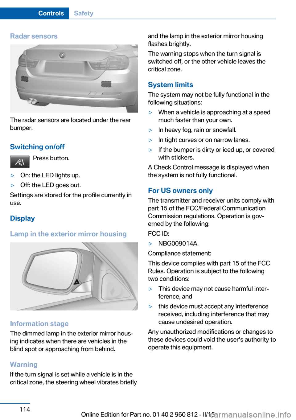
The radar sensors are located under the rear
bumper.
Switching on/off Press button.
▷On: the LED lights up.▷Off: the LED goes out.
Settings are stored for the profile currently in
use.
Display
Lamp in the exterior mirror housing
Information stage
The dimmed lamp in the exterior mirror hous‐
ing indicates when there are vehicles in the
blind spot or approaching from behind.
Warning If the turn signal is set while a vehicle is in the
critical zone, the steering wheel vibrates briefly
and the lamp in the exterior mirror housing
flashes brightly.
The warning stops when the turn signal is
switched off, or the other vehicle leaves the
critical zone.
System limits
The system may not be fully functional in the
following situations:▷When a vehicle is approaching at a speed
much faster than your own.▷In heavy fog, rain or snowfall.▷In tight curves or on narrow lanes.▷If the bumper is dirty or iced up, or covered
with stickers.
A Check Control message is displayed when
the system is not fully functional.
For US owners only The transmitter and receiver units comply with
part 15 of the FCC/Federal Communication
Commission regulations. Operation is gov‐
erned by the following:
FCC ID:
▷NBG009014A.
Compliance statement:
This device complies with part 15 of the FCC
Rules. Operation is subject to the following
two conditions:
▷This device may not cause harmful inter‐
ference, and▷this device must accept any interference
received, including interference that may
cause undesired operation.
Any unauthorized modifications or changes to
these devices could void the user's authority to
operate this equipment.
Seite 114ControlsSafety114
Online Edition for Part no. 01 40 2 960 812 - II/15
Page 120 of 226

Driving stability control systemsVehicle features and optionsThis chapter describes all standard, country-
specific and optional features offered with the
series. It also describes features that are not
necessarily available in your car, e. g., due to
the selected options or country versions. This
also applies to safety-related functions and
systems. The respectively applicable country
provisions must be observed when using the
respective features and systems.
Antilock Brake System ABS ABS prevents locking of the wheels during
braking.
The vehicle contains its steering power even
during full brake applications, thus increasing
active safety.
ABS is operational every time you start the en‐
gine.
Brake assistant When you apply the brakes rapidly, this system
automatically produces the greatest possible
braking force boost. It reduces the braking dis‐
tance to a minimum during emergency stop.
This system utilizes all of the benefits provided
by ABS.
Do not reduce the pressure on the brake pedal
for the duration of the emergency stop.
M Drive The conceptIndividual settings can be carried out in two
preassigned configurations for the vehicle.When the engine is started, an efficient driving
state is active by default. M Drive is deacti‐
vated.
At a glance
Configurations
The configurations are preassigned as follows:▷"M Drive 1": relaxed, comfortable driving.▷"M Drive 2": sporty, dynamic driving.
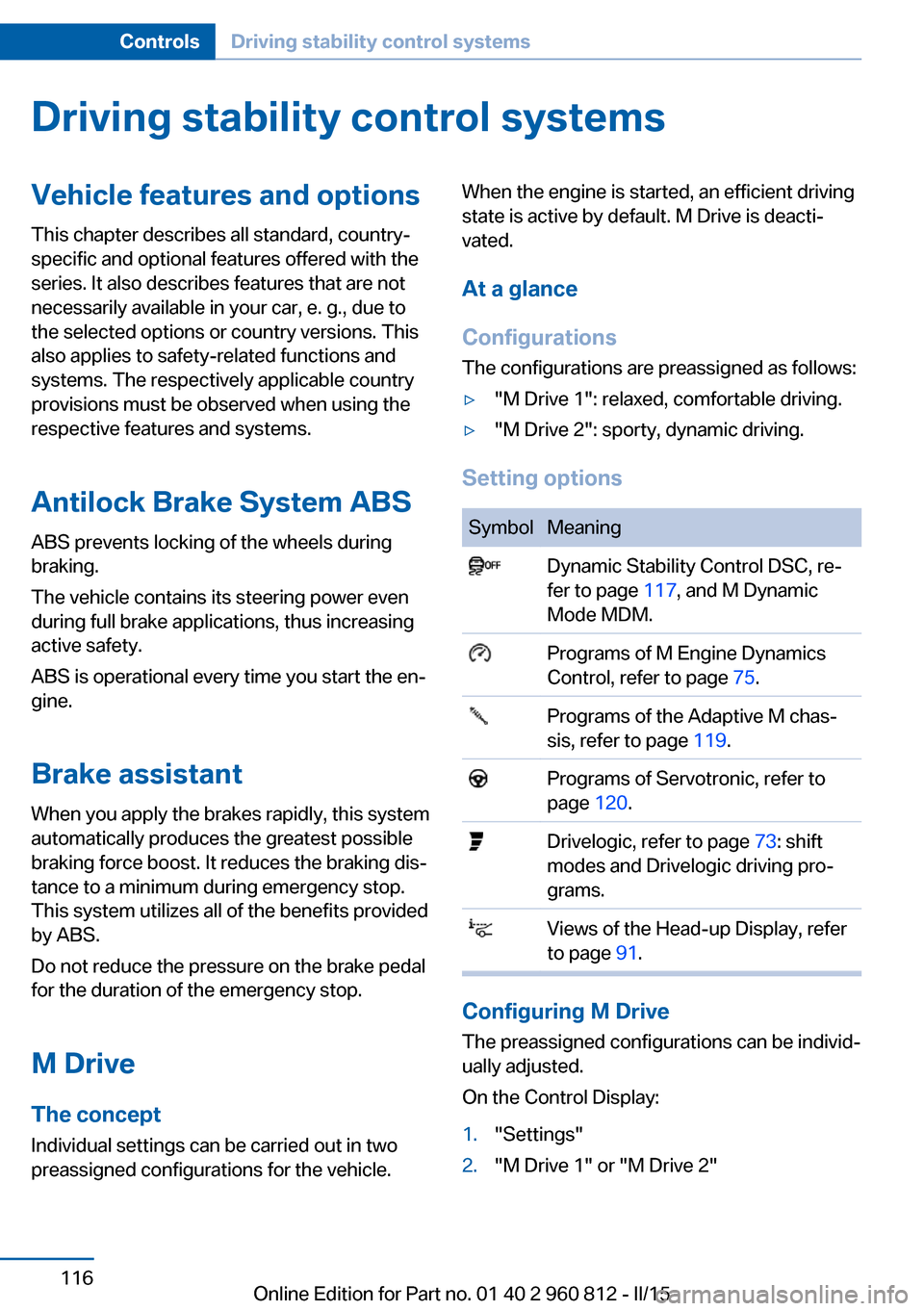
Setting options
SymbolMeaning Dynamic Stability Control DSC, re‐
fer to page 117, and M Dynamic
Mode MDM. Programs of M Engine Dynamics
Control, refer to page 75. Programs of the Adaptive M chas‐
sis, refer to page 119. Programs of Servotronic, refer to
page 120. Drivelogic, refer to page 73: shift
modes and Drivelogic driving pro‐
grams. Views of the Head-up Display, refer
to page 91.
Configuring M Drive
The preassigned configurations can be individ‐
ually adjusted.
On the Control Display:
1."Settings"2."M Drive 1" or "M Drive 2"Seite 116ControlsDriving stability control systems116
Online Edition for Part no. 01 40 2 960 812 - II/15
Page 130 of 226

▷Under certain weather conditions such as
high relative humidity, rain, snowfall, ex‐
treme heat or strong wind.▷With tow bars and trailer couplings of other
vehicles.▷With thin or wedge-shaped objects.▷With moving objects.▷With elevated, protruding objects such as
ledges or cargo.▷With objects with corners and sharp edges.▷With objects with a fine surface structure
such as fences.▷For objects with porous surfaces.
Low objects already displayed, e.g., curbs, can
move into the blind area of the sensors before
or after a continuous tone sounds.
False warnings
PDC may issue a warning under the following conditions even though there is no obstacle
within the detection range:
▷In heavy rain.▷When sensors are very dirty or covered
with ice.▷When sensors are covered in snow.▷On rough road surfaces.▷On uneven surfaces, such as speed
bumps.▷In large buildings with right angles and
smooth walls, e.g., in underground ga‐
rages.▷In automatic car washes.▷Through heavy pollution.▷Due to other ultrasound sources, e.g.,
sweeping machines, high pressure steam
cleaners or neon lights.
The malfunction is signaled by a continu‐
ous tone alternating between the front and
rear speakers. As soon as the malfunction
due to other ultrasound sources is no lon‐ger present, the system is again fully func‐
tional.
Malfunction
A Check Control message is displayed.
The range of the sensors is shown as a shaded
area on the Control Display.
PDC has failed. Have the system checked.
To ensure full functionality:
▷Keep the sensors clean and free of ice.▷dimmedDo not put any stickers on sen‐
sors.▷When using high-pressure washers, do not
spray the sensors for long periods and
maintain a distance of at least 12 in/30 cm.
Surround View
The concept Surround View comprises various camera as‐
sistance systems that help the driver when
parking, maneuvering, and at complex exits
and intersections.
▷Rearview camera, refer to page 126▷Side View, refer to page 129.▷Top View, refer to page 130.
Rearview camera
The concept The rearview camera provides assistance in
parking and maneuvering backwards. The area
behind the vehicle is shown on the Control
Display.
Seite 126ControlsDriving comfort126
Online Edition for Part no. 01 40 2 960 812 - II/15
Page 131 of 226

HintsCheck the traffic situation as well
Check the traffic situation around the ve‐
hicle with your own eyes. Otherwise, an acci‐
dent could result from road users or objects
that are not lidtured by the camera.◀
At a glance
Button in the vehicle
Rearview camera
Camera
The camera lens is located in the handle of the
tail gate. The image quality may be impaired by
dirt.
Clean the camera lens, refer to page 207.
Switching on/off
Switching on automatically With the engine running, engage lever in posi‐
tion P R.
The rearview camera image is displayed if the
system was switched on via the iDrive.
Automatic deactivation during forward
travel
The system switches off when a certain driving
distance or speed is exceeded.
Switch the system back on if needed.
Switching on/off manually Press button.▷On: the LED lights up.▷Off: the LED goes out.
The PDC is shown on the Control Display.
Switching the view via iDrive With PDC activated or Top View switched on:
"Rear view camera"
The rearview camera image is displayed.
Display on the Control Display
Functional requirement
▷The rearview camera is switched on.▷The trunk lid is fully closed.
Activating assistance functions
More than one assistance function can be ac‐
tive at the same time.
▷Parking aid lines
"Parking aid lines"
Lanes and turning radius are indicated.
▷Obstacle marking
"Obstacle marking"
Spatially-shaped markings are displayed.
Seite 127Driving comfortControls127
Online Edition for Part no. 01 40 2 960 812 - II/15
Page 134 of 226

Switching on/off
Switching on/off manually Press button.
Automatic deactivation during forward
travel
The system switches off when a certain driving
distance or speed is exceeded.
Switch the system back on if needed.
Display
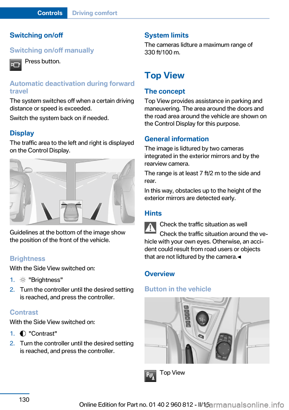
The traffic area to the left and right is displayed
on the Control Display.
Guidelines at the bottom of the image show
the position of the front of the vehicle.
Brightness With the Side View switched on:
1. "Brightness"2.Turn the controller until the desired setting
is reached, and press the controller.
Contrast
With the Side View switched on:
1. "Contrast"2.Turn the controller until the desired setting
is reached, and press the controller.System limits
The cameras lidture a maximum range of
330 ft/100 m.
Top View
The concept Top View provides assistance in parking and
maneuvering. The area around the doors and
the road area around the vehicle are shown on
the Control Display for this purpose.
General information
The image is lidtured by two cameras
integrated in the exterior mirrors and by the
rearview camera.
The range is at least 7 ft/2 m to the side and
rear.
In this way, obstacles up to the height of the
exterior mirrors are detected early.
Hints Check the traffic situation as well
Check the traffic situation around the ve‐
hicle with your own eyes. Otherwise, an acci‐
dent could result from road users or objects
that are not lidtured by the camera.◀
Overview
Button in the vehicle
Top View
Seite 130ControlsDriving comfort130
Online Edition for Part no. 01 40 2 960 812 - II/15
Page 135 of 226

Cameras
The lenses of the Top View camera are located
at the bottom in the mirror housings. The im‐
age quality may be impaired by dirt.
Clean the camera lenses, refer to page 207.
Switching on/off
Switching on automatically With the engine running, engage lever in posi‐
tion P R.
The Top View and PDC images are displayed if
the system is switched on via iDrive.
Automatic deactivation during forward
travel
The system switches off when a certain driving
distance or speed is exceeded.
Switch the system back on if needed.
Switching on/off manually Press button.
▷On: the LED lights up.▷Off: the LED goes out.
Top View is displayed.
Display
Visual warning
The approach of the vehicle to an object can
be shown on the Control Display.
When the distance to an object is small, a red
bar is shown in front of the vehicle, as it is in
the PDC display.
The display appears as soon as Top View is
activated.
When the image of the rearview camera is dis‐
played, it is possible to reel to top view:
"Rear view camera"
Brightness
With Top View switched on:
1. Select the symbol.2.Turn the controller until the desired setting
is reached, and press the controller.
Contrast
With Top View switched on:
1. Select the symbol.2.Turn the controller until the desired setting
is reached, and press the controller.
Displaying the turning radius and
pathway lines
▷The static, red turning radius line shows
the space needed to the side of the vehicle
when the steering wheel is turned all the
way.▷The variable, green pathway line assists
you in assessing the amount of space ac‐
tually needed to the side of the vehicle.
The lane line depends on the engaged
gear and the current steering angle. TheSeite 131Driving comfortControls131
Online Edition for Part no. 01 40 2 960 812 - II/15
Page 136 of 226

track line is continuously adjusted for the
steering wheel movement.
"Parking aid lines"
Turning circle and pathway lines are displayed.
System limits
Top View cannot be used in the following sit‐
uations:
▷With a door open.▷With the trunk lid open.▷With an exterior mirror folded in.▷In poor light.
A Check Control message is displayed in some
of these situations.
Parking assistant The concept
This system assists the driver in parking paral‐
lel to the road.
Ultrasound sensors measure parking spaces
on both sides of the vehicle.
The parking assistant calculates the best pos‐
sible parking line and takes control of steering
during the parking procedure.
When parking, also take note of the visual and
acoustic information and instructions issued
by the PDC, the parking assistant and the rear‐
view camera and react accordingly.
A component of the parking assistant is the
PDC Park Distance Control, refer to page 124.
Hints
Personal responsibility
Even an active system does not relieve
the driver from personal responsibility while
driving.
Technically the system has its limits, it cannot
independently react to all traffic situations.
Monitor your driving, be on the alert, observe
the vehicle surroundings and other traffic and
react when needed - risk of accident.◀
Changes to the parking space
Changes to the parking space after it was
measured are not taken into account by the system.
Therefore, always be alert and ready to inter‐
vene; otherwise, there is the risk of an acci‐
dent.◀
Transporting cargo
Cargo that extends beyond the perimeter
of the vehicle is not taken into account by the
system during the parking procedure.
Therefore, always be alert and ready to inter‐
vene; otherwise, there is the risk of an acci‐
dent.◀
Curbs
The parking assistant may steer the vehi‐
cle over or onto curb if need be.
Therefore, always be alert and ready to inter‐
vene; otherwise, the wheels, tires, or the vehi‐
cle may become damaged.◀
An engine that has been switched off by the
Auto Start Stop function is restarted automati‐
cally when the parking assistant is activated.
Requirements
For measuring parking spaces▷Maximum speed while driving forward ap‐
prox. 22 mph/35 km/h.Seite 132ControlsDriving comfort132
Online Edition for Part no. 01 40 2 960 812 - II/15