2016 BMW M2 power steering
[x] Cancel search: power steeringPage 14 of 220

CockpitVehicle features and options
This chapter describes all standard, country-
specific and optional features offered with the
series. It also describes features that are not
necessarily available in your car, e. g., due tothe selected options or country versions. This
also applies to safety-related functions and
systems. The respectively applicable country
provisions must be observed when using the
respective features and systems.
All around the steering wheel
1Power windows 452Exterior mirror operation 573Glove compartment on the driver's
side 144
Driver assistance systemsIntelligent Safety 105Lane departure warning 1114LightsLights off
Daytime running lights 95Parking lights 93Low beams 93Seite 14At a glanceCockpit14
Online Edition for Part no. 01 40 2 970 518 - II/16
Page 35 of 220

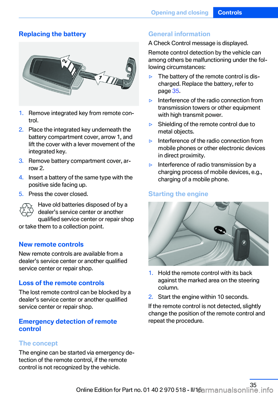
Replacing the battery1.Remove integrated key from remote con‐
trol.2.Place the integrated key underneath the
battery compartment cover, arrow 1, and
lift the cover with a lever movement of the
integrated key.3.Remove battery compartment cover, ar‐
row 2.4.Insert a battery of the same type with the
positive side facing up.5.Press the cover closed.
Have old batteries disposed of by a
dealer’s service center or another
qualified service center or repair shop
or take them to a collection point.
New remote controlsNew remote controls are available from a
dealer’s service center or another qualified
service center or repair shop.
Loss of the remote controls
The lost remote control can be blocked by a
dealer’s service center or another qualified
service center or repair shop.
Emergency detection of remote
control
The concept The engine can be started via emergency de‐
tection of the remote control, if the remote
control is not recognized by the vehicle.
General information
A Check Control message is displayed.
Remote control detection by the vehicle can
among others be malfunctioning under the fol‐
lowing circumstances:▷The battery of the remote control is dis‐
charged. Replace the battery, refer to
page 35.▷Interference of the radio connection from
transmission towers or other equipment
with high transmit power.▷Shielding of the remote control due to
metal objects.▷Interference of the radio connection from
mobile phones or other electronic devices
in direct proximity.▷Interference of radio transmission by a
charging process of mobile devices, e.g.,
charging of a mobile phone.
Starting the engine
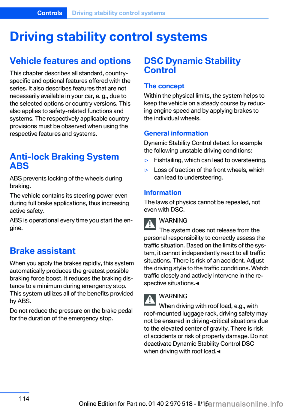
1.Hold the remote control with its back
against the marked area on the steering
column.2.Start the engine within 10 seconds.
If the remote control is not detected, slightly
change the position of the remote control and
repeat the procedure.
Seite 35Opening and closingControls35
Online Edition for Part no. 01 40 2 970 518 - II/16
Page 114 of 220

Driving stability control systemsVehicle features and optionsThis chapter describes all standard, country-
specific and optional features offered with the
series. It also describes features that are not
necessarily available in your car, e. g., due to
the selected options or country versions. This
also applies to safety-related functions and
systems. The respectively applicable country
provisions must be observed when using the
respective features and systems.
Anti-lock Braking System
ABS
ABS prevents locking of the wheels during
braking.
The vehicle contains its steering power even
during full brake applications, thus increasing
active safety.
ABS is operational every time you start the en‐
gine.
Brake assistant When you apply the brakes rapidly, this system
automatically produces the greatest possible
braking force boost. It reduces the braking dis‐
tance to a minimum during emergency stop.
This system utilizes all of the benefits provided
by ABS.
Do not reduce the pressure on the brake pedal
for the duration of the emergency stop.DSC Dynamic Stability
Control
The concept Within the physical limits, the system helps to
keep the vehicle on a steady course by reduc‐
ing engine speed and by applying brakes to
the individual wheels.
General information Dynamic Stability Control detect for example
the following unstable driving conditions:▷Fishtailing, which can lead to oversteering.▷Loss of traction of the front wheels, which
can lead to understeering.
Information
The laws of physics cannot be repealed, not
even with DSC.
WARNING
The system does not release from the
personal responsibility to correctly assess the
traffic situation. Based on the limits of the sys‐
tem, it cannot independently react to all traffic
situations. There is risk of an accident. Adjust
the driving style to the traffic conditions. Watch
traffic closely and actively intervene in the re‐
spective situations.◀
WARNING
When driving with roof load, e.g., with
roof-mounted luggage rack, driving safety may
not be ensured in driving-critical situations due
to the elevated center of gravity. There is risk
of accidents or risk of property damage. Do not
deactivate Dynamic Stability Control DSC
when driving with roof load.◀
Seite 114ControlsDriving stability control systems114
Online Edition for Part no. 01 40 2 970 518 - II/16
Page 115 of 220

Overview
Button in the vehicle
DSC OFF button
Indicator/warning lights The indicator lamp flashes: DSC con‐
trols the drive and braking forces.
The indicator lamp lights up: DSC has
failed.
Deactivating DSC: DSC OFF
General information
When DSC is deactivated, driving stability is
reduced during acceleration and when driving
in curves.
To increase vehicle stability, activate DSC
again as soon as possible.
Deactivating DSC Press and hold this button but not longer
than approx. 10 seconds, until the indica‐
tor lamp for DSC OFF lights up in the instru‐
ment cluster and displays DSC OFF.
DSC is switched off.
Engine tuning switches to a sportier setting.
Activating DSC Press button.
DSC OFF and the DSC OFF indicator lamp go
out.
Indicator/warning lights When DSC is deactivated, DSC OFF is dis‐
played in the instrument cluster.
The indicator lamp lights up: DSC is
deactivated.
M Dynamic Mode MDM
The concept M Dynamic Mode makes it possible to drive on
a dry roadway with high longitudinal and trans‐
verse acceleration but with limited driving sta‐
bility.
Only in the absolute limit area does the system
intervene for stabilization by reducing the en‐
gine power and by braking interventions on the
wheels. In this driving condition, additional
steering corrections may be necessary.
You may find it useful to briefly activate MDM
under the following special circumstances:▷When driving in slush or on uncleared,
snow-covered roads.▷When freeing vehicle from deep snow or
driving off from loose grounds.▷When driving with snow chains.
Information
WARNING
When M Dynamic Mode is activated, sta‐
bilizing interventions are carried out only to a
reduced extent. There is a risk of accidents or
a risk of property damage. Adapt to traffic con‐
ditions. Watch traffic closely and actively inter‐
fere in the respective situations. In the event of
a warning, do not unnecessarily jerk the steer‐
ing wheel.◀
To increase vehicle stability, activate DSC
again as soon as possible.
Seite 115Driving stability control systemsControls115
Online Edition for Part no. 01 40 2 970 518 - II/16
Page 121 of 220

▷Each time the rocker switch is pressed to
the point of resistance, the desired speed
increases or decreases by approx.
1 mph/1 km/h.▷Each time the rocker switch is pressed
past the point of resistance, the desired
speed increases or decreases by a maxi‐
mum of 5 mph/10 km/h.
The maximum speed that can be set de‐
pends on the vehicle.▷Pressing the rocker switch to the resist‐
ance point and holding it accelerates or de‐
celerates the vehicle without requiring
pressure on the accelerator pedal.
After the rocker switch is released, the ve‐
hicle maintains its final speed. Pressing the
switch beyond the resistance point causes
the vehicle to accelerate more rapidly.
Continuing cruise control
General information
An interrupted cruise control can be continued
by calling up the stored speed.
In the following cases, the stored speed value
is deleted and cannot be called up again:
▷When the system is switched off.▷When the ignition is switched off.
Information
Make sure that the difference between current
speed and stored speed is not too large before
calling up the stored speed. Otherwise, unin‐
tentional braking or accelerating may occur.
Calling up stored speed Press button on the steering wheel.
The stored speed is reached and maintained.
Displays in the instrument cluster
Indicator lamp Depending on how the vehicle is equip‐
ped, the indicator lamp in the instru‐
ment cluster indicates whether the sys‐
tem is switched on.
Desired speed and stored speed▷Marking lights up green:
system is active, the mark‐
ing indicates the desired
speed.▷Marking lights up orange:
system is interrupted, the
marking indicates the stored
speed.▷The marking does not light up: the system
is switched off.
Brief status display
Selected desired speed.
If no speed is indicated, it is possible that the
conditions necessary for operation are not cur‐
rently fulfilled.
System limits
Engine power The desired speed is also maintained downhill,
but may not be maintained on uphill grades if
engine power is insufficient.
PDC Park Distance Control The concept
PDC is a support when parking. When you
slowly approach an object in the rear, then the
object is reported through:
▷Signal tones.Seite 121Driving comfortControls121
Online Edition for Part no. 01 40 2 970 518 - II/16
Page 137 of 220

World map with magnetic zonesProcedure1.Press and hold the control button for ap‐
prox. 3 to 4 seconds. The number of the
set compass zone appears in the mirror.2.To change the zone setting, press the con‐
trol button quickly and repeatedly until the
number of the compass zone that corre‐
sponds with your location appears in the
mirror.
The set zone is stored automatically. The com‐
pass is ready for use again after approximately
10 seconds.
Calibrating the digital compass
The digital compass must be calibrated in the
event of the following:
▷The wrong compass point is displayed.▷The point of the compass displayed does
not change despite changing the direction
of travel.▷Not all points of the compass are dis‐
played.Procedure1.Make sure that there are no large metallic
objects or overhead power lines near the
vehicle and that there is sufficient room to
drive around in a circle.2.Set the currently applicable compass zone.3.Press and hold the control button for ap‐
prox. 6 to 7 seconds so that "C" appears
on the display. Next, drive in a complete
circle at least once at a speed of no more
than 4 mph/7 km/h. If calibration is suc‐
cessful, the "C" is replaced by the points of
the compass.
Left/right-hand steering
The digital compass is already set for right or
left-hand steering at the factory.
Setting the language
Press and hold the control button for approx.
12 to 13 seconds. Briefly press the control
button again to switch between English "E"
and German "O".
Seite 137Interior equipmentControls137
Online Edition for Part no. 01 40 2 970 518 - II/16
Page 196 of 220

corresponding engine or body ground of
the vehicle to be started.
Starting the engine
Never use spray fluids to start the engine.
1.Start the engine of the assisting vehicle
and let it run for several minutes at an in‐
creased idle speed.2.Start the engine of the vehicle that is to be
started in the usual way.
If the first starting attempt is not success‐
ful, wait a few minutes before making an‐
other attempt in order to allow the dis‐
charged battery to recharge.3.Let both engines run for several minutes.4.Disconnect the jumper cables in the re‐
verse order.
Check the battery and recharge if needed.
Tow-starting and towing Information WARNING
Due to system limits, individual functions
can malfunction during tow-starting/towing
with the Intelligent Safety systems activated,
e.g., approach control warning with light brak‐
ing function. There is risk of an accident.
Switch all Intelligent Safety systems off prior to
tow-starting/towing.◀
Manual transmission
Gearshift lever in neutral position.
Towing Follow the following instructions:
▷Make sure that the ignition is switched on;
otherwise, the low beams, tail lamps, turn
signals, and wipers may be unavailable.▷Do not tow the vehicle with the rear axle
tilted, as the front wheels could turn.▷When the engine is stopped, there is no
power assist. Consequently, more force
needs to be applied when braking and
steering.▷Larger steering wheel movements are re‐
quired.▷The towing vehicle must not be lighter
than the vehicle being towed; otherwise,
it will not be possible to control the vehi‐
cle's response.▷Do not exceed a towing speed of
30 mph/50 km/h.▷Do not exceed a towing distance of
30 miles/50 km.
Tow truck
With rear-wheel drive
Your vehicle should be transported with a tow
truck with a so-called lift bar or on a flat bed.
ATTENTION
When lifting the vehicle by the tow fitting
or body and chassis parts; damage can occur
on vehicle parts. There is a risk of damage to
property. Lift vehicle using suitable means.◀
M double-clutch transmission:
transporting the vehicle
Information The vehicle is not permitted to be towed.
Seite 196MobilityBreakdown assistance196
Online Edition for Part no. 01 40 2 970 518 - II/16
Page 215 of 220

Mounting of child restraintsystems 62
M technology 150
Multifunction steering wheel, buttons 14
Multimedia 6
N
Navigation 6
Neck restraints, front, see Head restraints 54
Neck restraints, rear, see Head restraints 55
Neutral cleaner, see wheel cleaner 201
New wheels and tires 171
O OBD Onboard Diagnosis 185
OBD, see OBD Onboard Di‐ agnosis 185
Obstacle marking, rearview camera 125
Octane rating, see Recom‐ mended fuel grade 167
Odometer 83
Office 6
Oil 179
Oil, adding 180
Oil additives 181
Oil change 181
Oil change interval, service requirements 85
Oil filler neck 180
Oil types, alternative 181
Oil types, suitable 181
Old batteries, disposal 191
Onboard computer 88
Onboard computer, see On‐ board computer 88
Onboard monitor, see Control Display 18
Onboard vehicle tool kit 186 Opening/closing via door
lock 39
Opening and closing 34
Opening and closing, without remote control 39
Opening and closing, with re‐ mote control 37
Operating concept, iDrive 18
Optional equipment 7
Outside air, see Automatic re‐ circulated-air control 131
Own Safety 7
P
Paint, vehicle 200
Park Distance Control PDC 121
Parked-car ventilation 132
Parked vehicle, condensa‐ tion 154
Parking aid, see PDC 121
Parking brake 70
Parking lights 93
Parts and accessories 8
Passenger side mirror, tilting downward 58
Pathway lines, rearview cam‐ era 125
PDC Park Distance Con‐ trol 121
Personal Profile 36
Personal Profile, exporting profiles 37
Personal Profile, importing profiles 37
Person warning with City light braking function 109
Pinch protection system, glass sunroof 48
Pinch protection system, win‐ dows 46
Plastic, care 201
Power failure 191
Power sunroof, glass 47
Power windows 45 Prescribed engine oil
types 181
Pressure, tire air pres‐ sure 168
Pressure warning, tires 104
Preventing Auto Start Stop 69
Profile, see Personal Pro‐ file 36
Programmable memory but‐ tons, iDrive 24
Protective function, glass sunroof 48
Protective function, win‐ dows 46
Push-and-turn switch, see Controller 19
R Racetrack operation 150
Radiator fluid 182
Radio 6
Radio-operated key, see Re‐ mote control 34
Radio ready state 65
Rain sensor 72
Ratchet straps, securing cargo 157
Rear lights 189
Rear socket 139
Rearview camera 124
Rearview mirror 57
Rear window de‐ froster 129, 132
Recirculated-air filter 132
Recirculated-air mode 128, 131
Recommended fuel grade 167
Recommended tire brands 172
Refueling 164
Remaining range 84
Remote control/key 34 Seite 215Everything from A to ZReference215
Online Edition for Part no. 01 40 2 970 518 - II/16