2016 BMW M2 display
[x] Cancel search: displayPage 117 of 220

Overview
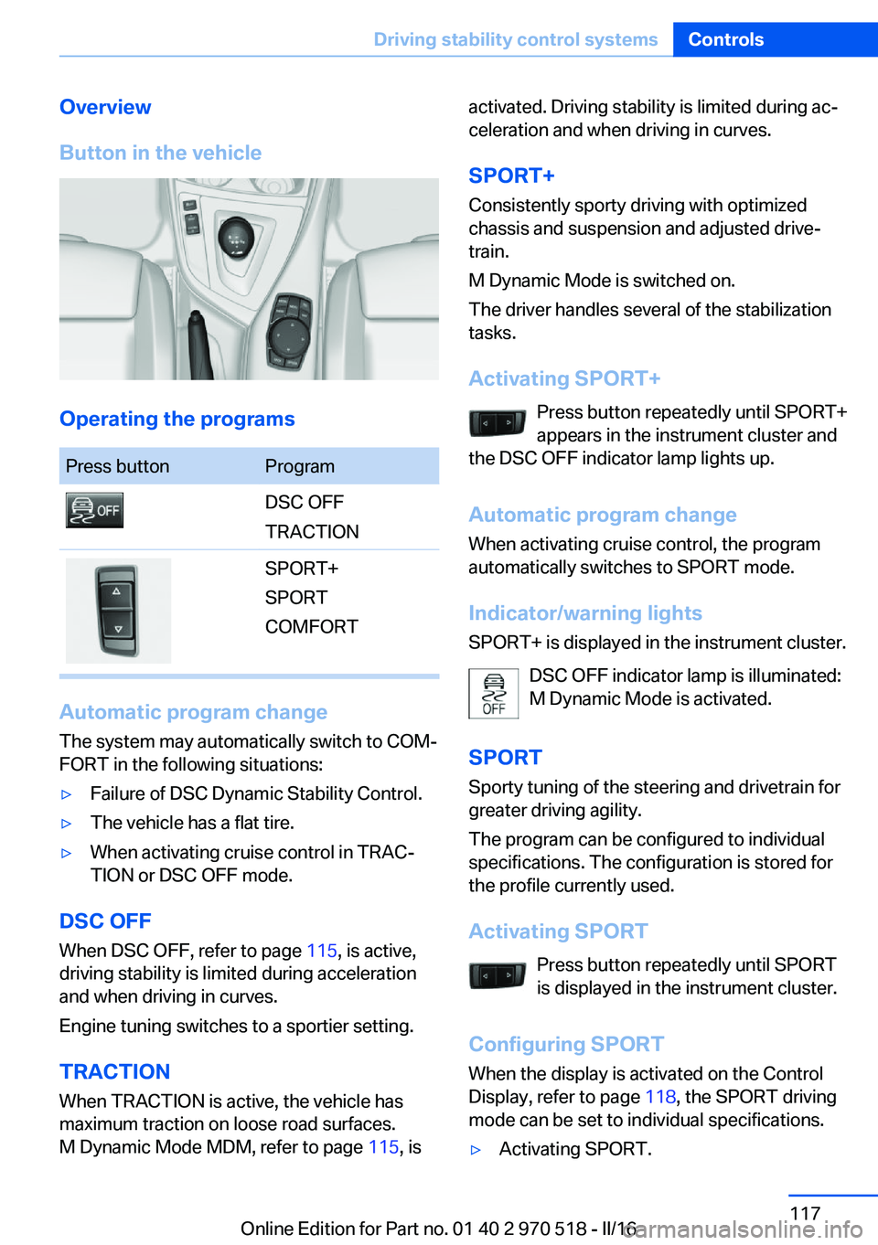
Button in the vehicle
Operating the programs
Press buttonProgramDSC OFF
TRACTIONSPORT+
SPORT
COMFORT
Automatic program change
The system may automatically switch to COM‐
FORT in the following situations:
▷Failure of DSC Dynamic Stability Control.▷The vehicle has a flat tire.▷When activating cruise control in TRAC‐
TION or DSC OFF mode.
DSC OFF
When DSC OFF, refer to page 115, is active,
driving stability is limited during acceleration
and when driving in curves.
Engine tuning switches to a sportier setting.
TRACTION When TRACTION is active, the vehicle has
maximum traction on loose road surfaces.
M Dynamic Mode MDM, refer to page 115, is
activated. Driving stability is limited during ac‐
celeration and when driving in curves.
SPORT+
Consistently sporty driving with optimized
chassis and suspension and adjusted drive‐
train.
M Dynamic Mode is switched on.
The driver handles several of the stabilization
tasks.
Activating SPORT+ Press button repeatedly until SPORT+
appears in the instrument cluster and
the DSC OFF indicator lamp lights up.
Automatic program change
When activating cruise control, the program
automatically switches to SPORT mode.
Indicator/warning lights
SPORT+ is displayed in the instrument cluster.
DSC OFF indicator lamp is illuminated:
M Dynamic Mode is activated.
SPORT Sporty tuning of the steering and drivetrain for
greater driving agility.
The program can be configured to individual
specifications. The configuration is stored for
the profile currently used.
Activating SPORT Press button repeatedly until SPORT
is displayed in the instrument cluster.
Configuring SPORT When the display is activated on the Control
Display, refer to page 118, the SPORT driving
mode can be set to individual specifications.▷Activating SPORT.Seite 117Driving stability control systemsControls117
Online Edition for Part no. 01 40 2 970 518 - II/16
Page 118 of 220

▷"Configure SPORT"▷Configuring the SPORT driving mode.
SPORT can also be configured before it is acti‐
vated:
1."Settings"2."Driving mode"3."Configure SPORT"4.Configure driving mode.
This configuration is retrieved when the
SPORT driving mode is activated.
COMFORT For a balanced tuning with maximum driving
stabilization.
Activating COMFORT Press button repeatedly until COM‐
FORT is displayed in the instrument
cluster.
In certain situations, the system automatically
changes to the NORMAL program, automatic
program change, refer to page 117.
Displays
Program selection Pressing the button displays a
list of the selectable programs.
Depending on your vehicle's op‐
tional features, the list in the in‐ strument cluster can differ from
the illustration shown.
Selected program The instrument cluster displays
the selected program.
Display on the Control Display
Program changes can be displayed on the
Control Display.1."Settings"2."Control display"3."Driving mode info"
Drive-off assistant
The concept This system supports driving off on inclines.
The parking brake is not required.
Driving off with the drive-off assistant
1.Hold the vehicle in place with the foot
brake.2.Release the foot brake and drive off with‐
out delay.
After the foot brake is released, the vehicle is
held in place for approx. 2 seconds.
Depending on the vehicle load, the vehicle may
roll back slightly.
Seite 118ControlsDriving stability control systems118
Online Edition for Part no. 01 40 2 970 518 - II/16
Page 120 of 220

Cruise control can be used.
DSC will be switched on if needed.
Switching off Press button on the steering wheel.▷If active: press twice.▷If interrupted: press once.
The displays go out. The stored desired speed
is deleted.
Interrupting manually When active, press the button on the
steering wheel.
Automatic interruption The system is automatically interrupted in the
following situations:
▷When the driver applies the brakes.▷If the clutch pedal is depressed for a few
seconds or released while a gear is not en‐
gaged.▷If the gear engaged is too high for the cur‐
rent speed.▷If MDM is activated or DSC is deactivated.▷When DSC is actively controlling stability.▷When SPORT+ is activated with Driving
Dynamics Control.Setting the speed
Maintaining/storing the speed
Press the rocker switch while the system is in‐
terrupted.
When the system is switched on, the current
speed is maintained and stored as the desired
speed.
The stored speed is displayed in the speedom‐
eter and briefly in the instrument cluster, refer
to page 121.
DSC will be switched on if needed.
The speed can also be stored by pressing a
button.
Press button.
Changing the speed
Press the rocker switch up or down repeatedly
until the desired speed is set.
If active, the displayed speed is stored and the
vehicle reaches the stored speed when the
road is clear.
Seite 120ControlsDriving comfort120
Online Edition for Part no. 01 40 2 970 518 - II/16
Page 121 of 220

▷Each time the rocker switch is pressed to
the point of resistance, the desired speed
increases or decreases by approx.
1 mph/1 km/h.▷Each time the rocker switch is pressed
past the point of resistance, the desired
speed increases or decreases by a maxi‐
mum of 5 mph/10 km/h.
The maximum speed that can be set de‐
pends on the vehicle.▷Pressing the rocker switch to the resist‐
ance point and holding it accelerates or de‐
celerates the vehicle without requiring
pressure on the accelerator pedal.
After the rocker switch is released, the ve‐
hicle maintains its final speed. Pressing the
switch beyond the resistance point causes
the vehicle to accelerate more rapidly.
Continuing cruise control
General information
An interrupted cruise control can be continued
by calling up the stored speed.
In the following cases, the stored speed value
is deleted and cannot be called up again:
▷When the system is switched off.▷When the ignition is switched off.
Information
Make sure that the difference between current
speed and stored speed is not too large before
calling up the stored speed. Otherwise, unin‐
tentional braking or accelerating may occur.
Calling up stored speed Press button on the steering wheel.
The stored speed is reached and maintained.
Displays in the instrument cluster
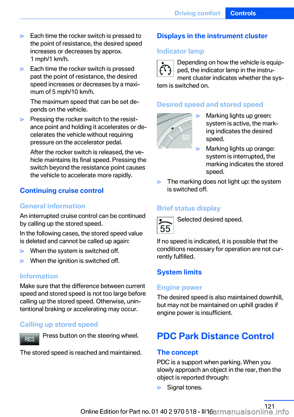
Indicator lamp Depending on how the vehicle is equip‐
ped, the indicator lamp in the instru‐
ment cluster indicates whether the sys‐
tem is switched on.
Desired speed and stored speed▷Marking lights up green:
system is active, the mark‐
ing indicates the desired
speed.▷Marking lights up orange:
system is interrupted, the
marking indicates the stored
speed.▷The marking does not light up: the system
is switched off.
Brief status display
Selected desired speed.
If no speed is indicated, it is possible that the
conditions necessary for operation are not cur‐
rently fulfilled.
System limits
Engine power The desired speed is also maintained downhill,
but may not be maintained on uphill grades if
engine power is insufficient.
PDC Park Distance Control The concept
PDC is a support when parking. When you
slowly approach an object in the rear, then the
object is reported through:
▷Signal tones.Seite 121Driving comfortControls121
Online Edition for Part no. 01 40 2 970 518 - II/16
Page 122 of 220

▷Visual display.
General information
Measurements are made through ultrasound
sensors in the rear bumper.
The maneuvering range, depending on the ob‐
stacle and environmental conditions, is approx.
6 ft/2 m.
An acoustic warning is first given with the fol‐
lowing circumstances:
▷By the two rear corner sensors at approx.
24 in/60 cm.▷By the rear middle sensors at approx.
5 ft/1.50 m.▷When a collision is imminent.
Information
WARNING
The system does not release from the
personal responsibility to correctly assess the
traffic situation. Based on the limits of the sys‐
tem, it cannot independently react to all traffic
situations. There is risk of an accident. Adjust
the driving style to the traffic conditions. Watch
traffic closely and actively intervene in the re‐
spective situations.◀
WARNING
Due to high speeds when PDC is acti‐
vated, the warning can be delayed due to
physical circumstances. There is a risk of injury
or risk of property damage. Avoid approaching
an object too fast. Avoid driving off fast while
PDC is not yet active.◀
Overview
Ultrasound sensors Ultrasound sensors of the PDC,
for example in the bumpers.
Functional requirements
To ensure full functionality:▷Do not cover sensors, for example, with
stickers, bicycle racks.▷Keep the sensors clean and free of ice.
To clean: when using high-pressure washers,
do not spray the sensors for long periods and
maintain a distance of at least 12 in‐
ches/30 cm.
Switching on/off
Switching on automatically
With the engine running, engage lever in posi‐
tion P R.
The rearview camera also switches on.
Automatic deactivation during forward
travel
The system switches off when a certain driving
distance or speed is exceeded.
Switch the system back on if needed.
Display
Signal tones When approaching an object, an intermittent
sound indicates the position of the object. E.g.
if an object is detected to the left rear of the
vehicle, a signal tone sounds from the left rear
speaker.
The shorter the distance to the object, the
shorter the intervals.
If the distance to a detected object is less than
approx. 10 inches/25 cm, a continuous tone is
sounded.
Volume The ratio of the PDC signal tone volume to the
entertainment volume can be adjusted.
1."Multimedia", "Radio" or "Settings"2."Tone"Seite 122ControlsDriving comfort122
Online Edition for Part no. 01 40 2 970 518 - II/16
Page 123 of 220

3."Volume settings"4."PDC"5.Turn the Controller until the desired set‐
ting is selected.6.Press the Controller.
Settings are stored for the profile currently
used.
Visual warning
The approach of the vehicle to an object can
be shown on the Control Display. Objects that
are farther away are already displayed on the
Control Display before a signal sounds.
A display appears as soon as Park Distance
Control (PDC) is activated.
The range of the sensors is represented in the
colors green, yellow and red.
When the image of the rearview camera is dis‐
played, the switch can be made to PDC:
"Rear view camera"
System limits
Information WARNING
The system can react incorrectly or not
at all due to the system limits. There is risk of
accidents or risk of property damage. Observe
the information regarding the system limits
and actively intervene, if needed.◀
Limits of ultrasonic measurement Ultrasonic measuring might not function under
the following circumstances:
▷For small children and animals.▷For persons with certain clothing, for ex‐
ample coats.▷With external interference of the ultra‐
sound, for example from passing vehicles
or loud machines.▷When sensors are dirty, iced over, dam‐
aged or out of position.▷Under certain weather conditions such as
high relative humidity, rain, snowfall, ex‐
treme heat or strong wind.▷With tow bars and trailer couplings of other
vehicles.▷With thin or wedge-shaped objects.▷With moving objects.▷With elevated, protruding objects such as
ledges or cargo.▷With objects with corners and sharp edges.▷With objects with a fine surface structure
such as fences.▷For objects with porous surfaces.▷If cargo protrudes.
Low objects already displayed, for example,
curbs, can move into the blind area of the sen‐
sors before or after a continuous tone sounds.
False warnings
PDC may issue a warning under the following
conditions even though there is no obstacle
within the detection range:
▷In heavy rain.▷When sensors are very dirty or covered
with ice.▷When sensors are covered in snow.▷On rough road surfaces.▷On uneven surfaces, such as speed
bumps.▷In large buildings with right angles and
smooth walls, for example, in underground
garages.▷In automatic car washes.▷Through heavy pollution.▷Due to other ultrasound sources, for exam‐
ple, sweeping machines, high pressure
steam cleaners or neon lights.Seite 123Driving comfortControls123
Online Edition for Part no. 01 40 2 970 518 - II/16
Page 124 of 220

As soon as the malfunction due to other ultra‐
sound sources is no longer present, the sys‐
tem is again fully functional.
Malfunction
A Check Control message is displayed.
The range of the sensors is shown as a shaded
area on the Control Display.
PDC has failed. Have the system checked.
Rearview camera The concept
The rearview camera provides assistance in
parking and maneuvering backwards. The area
behind the vehicle is shown on the Control
Display.
Information WARNING
The system does not relieve from the
personal responsibility to correctly assess the
traffic situation. There is risk of an accident.
Adjust the driving style to the traffic condi‐
tions. Watch traffic and vehicle surroundings
closely and actively intervene in the respective
situations.◀Overview
Camera
The camera lens is located in the handle of the
tailgate. The image quality may be impaired by
dirt.
Clean the camera lens, refer to page 202.
Switching on/off
Switching on automatically With the engine running, engage lever in posi‐
tion P R.
The rearview camera image is displayed if the
system was switched on via the iDrive.
Automatic deactivation during forward
travel
The system switches off when a certain driving
distance or speed is exceeded.
Switch the system back on if needed.
Switching the view via iDrive With PDC activated:
"Rear view camera"
The rearview camera image is displayed.
Display on the Control Display
Functional requirement
▷The rearview camera is switched on.▷The tailgate is fully closed.Seite 124ControlsDriving comfort124
Online Edition for Part no. 01 40 2 970 518 - II/16
Page 125 of 220

▷Keep the recording range of the camera
clear. Protruding cargo can lead to mal‐
functions.
Activating assistance functions
More than one assistance function can be ac‐
tive at the same time.
▷Parking aid lines
"Parking aid lines"
Lanes and turning radius are indicated.
▷Obstacle marking
"Obstacle marking"
Spatially-shaped markings are displayed.
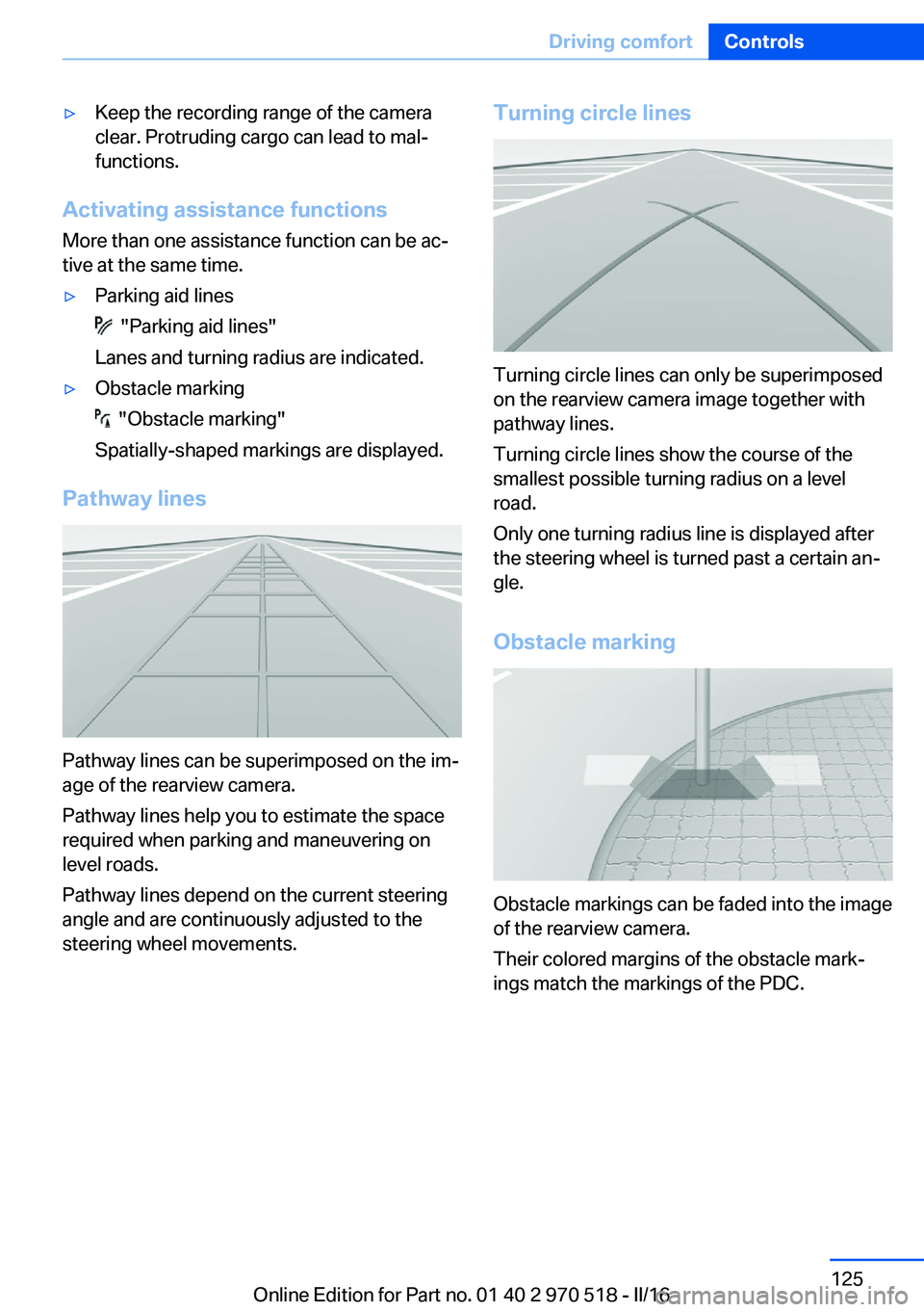
Pathway lines
Pathway lines can be superimposed on the im‐
age of the rearview camera.
Pathway lines help you to estimate the space
required when parking and maneuvering on
level roads.
Pathway lines depend on the current steering
angle and are continuously adjusted to the
steering wheel movements.
Turning circle lines
Turning circle lines can only be superimposed
on the rearview camera image together with
pathway lines.
Turning circle lines show the course of the
smallest possible turning radius on a level
road.
Only one turning radius line is displayed after
the steering wheel is turned past a certain an‐
gle.
Obstacle marking
Obstacle markings can be faded into the image
of the rearview camera.
Their colored margins of the obstacle mark‐
ings match the markings of the PDC.
Seite 125Driving comfortControls125
Online Edition for Part no. 01 40 2 970 518 - II/16