2016 BMW M2 light
[x] Cancel search: lightPage 186 of 220
Replacing componentsVehicle features and optionsThis chapter describes all standard, country-
specific and optional features offered with the
series. It also describes features that are not
necessarily available in your car, e. g., due to
the selected options or country versions. This
also applies to safety-related functions and
systems. The respectively applicable country
provisions must be observed when using the
respective features and systems.
Onboard vehicle tool kit
The onboard vehicle tool kit is located under
the cargo floor panel.
Wiper blade replacement Information ATTENTION
If the wiper arm falls onto the windshield
without the wiper blades installed, the wind‐
shield can be damaged. There is a risk of dam‐
age to property. Secure the wiper arm when
replacing the wiper blades and do not fold
down the wipers without the wiper blades in‐
stalled.◀
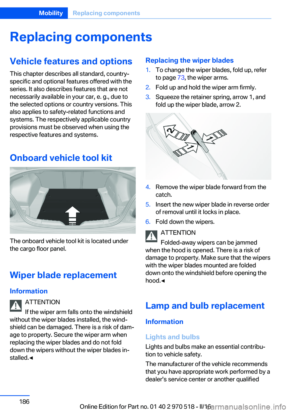
Replacing the wiper blades1.To change the wiper blades, fold up, refer
to page 73, the wiper arms.2.Fold up and hold the wiper arm firmly.3.Squeeze the retainer spring, arrow 1, and
fold up the wiper blade, arrow 2.4.Remove the wiper blade forward from the
catch.5.Insert the new wiper blade in reverse order
of removal until it locks in place.6.Fold down the wipers.
ATTENTION
Folded-away wipers can be jammed
when the hood is opened. There is a risk of
damage to property. Make sure that the wipers
with the wiper blades mounted are folded
down onto the windshield before opening the
hood.◀
Lamp and bulb replacement Information
Lights and bulbs
Lights and bulbs make an essential contribu‐
tion to vehicle safety.
The manufacturer of the vehicle recommends
that you have appropriate work performed by a
dealer’s service center or another qualified
Seite 186MobilityReplacing components186
Online Edition for Part no. 01 40 2 970 518 - II/16
Page 187 of 220
service center or repair shop if you are unfami‐
liar with it or if it has not been described here.
A spare lamp box is available from a dealer’s
service center or another qualified service cen‐
ter or repair shop.
WARNING
Bulbs can get hot during operation. Con‐
tact with the bulbs can cause burns. There is a
risk of injuries. Only change bulbs after they
have cooled off.◀
WARNING
Work on switched-on lighting systems
can cause short circuits. There is a risk of inju‐
ries or a risk of property damage. When work‐
ing on the lighting system, switch off the lamps
in question. If necessary, heed the bulb manu‐
facturer's instructions.◀
DANGER
There can be high voltage in the lighting
system. There is danger to life. The manufac‐
turer of your vehicle recommends that the
work on the lighting system including bulb re‐
placement be performed by a dealer’s service
center or another qualified service center or re‐
pair shop.◀
CAUTION
Dirty bulbs have a reduced service life.
There is a risk of property damage. Do not hold
new bulbs with your bare hands. Use a clean
cloth or something similar, or hold the bulb by
its base.◀
Light-emitting diodes (LEDs)
Some items of equipment use light-emitting
diodes installed behind a cover as a light
source.
These light-emitting diodes, which are related
to conventional lasers, are officially designated as Class 1 light-emitting diodes.WARNING
Too intensive brightness can irritate or
damage the retina of the eye. There is a a risk
of injury. Do not look directly into the head‐
lights or other light sources. Do not remove the
LED covers.◀
Headlight glass
Condensation can form on the inside of the ex‐
ternal lights in cool or humid weather. When
driving with the lights switched on, the con‐
densation evaporates after a short time. The
headlight glass does not need to be changed.
If despite driving with the lights switched on,
increasing humidity forms, e. g. water droplets
in the lamp, the manufacturer of your vehicle
recommends having it checked by a dealer’s
service center or another qualified service cen‐
ter or repair shop.
Headlight setting
The headlight adjustments can be affected by
changing lights and bulbs. After the headlight
adjustment was changed, have it checked and,
if necessary, corrected by a dealer’s service
center or another qualified service center or re‐ pair shop.
Front lights, bulb replacement
Xenon headlights
Information DANGER
There can be high voltage in the lighting
system. There is danger to life. The manufac‐
turer of your vehicle recommends that the
work on the lighting system including bulb re‐
placement be performed by a dealer’s service
center or another qualified service center or re‐
pair shop.◀
Because of the long life of these bulbs, the
likelihood of failure is very low. Switching the
lights on and off frequently shortens their life.Seite 187Replacing componentsMobility187
Online Edition for Part no. 01 40 2 970 518 - II/16
Page 188 of 220

For checking and adjusting headlamp aim,
contact a dealer’s service center or another
qualified service center or repair shop.
Overview1Parking lights / daytime running lights2Low beams/high beams/headlight flasher3Turn signal
Xenon headlights
Low beams and high beams are designed with
xenon technology.
The parking lights and daylight running lights
are made using LED technology.
In the case of a malfunction, contact a dealer’s
service center or another qualified service cen‐
ter or repair shop.
Turn signal
Follow general instructions, refer to page 186.
21-watt bulb, PY21W1.In the wheel house, loosen the two brack‐
ets and remove the cover.2.If necessary, pull the inside trim of the
wheel house slightly inward. Turn the bulb
socket counterclockwise and remove.3.Press the bulb gently into the socket, turn
counterclockwise and remove.4.Install the new bulb and bulb holder in re‐
verse order of removal.5.Attach the cover to the wheel house.
Turn signal in exterior mirror
The turn signals in the exterior mirrors feature
LED technology. In the case of a malfunction,
contact a dealer’s service center or another
qualified service center or repair shop.
Seite 188MobilityReplacing components188
Online Edition for Part no. 01 40 2 970 518 - II/16
Page 189 of 220
Tail lamps, bulb replacement
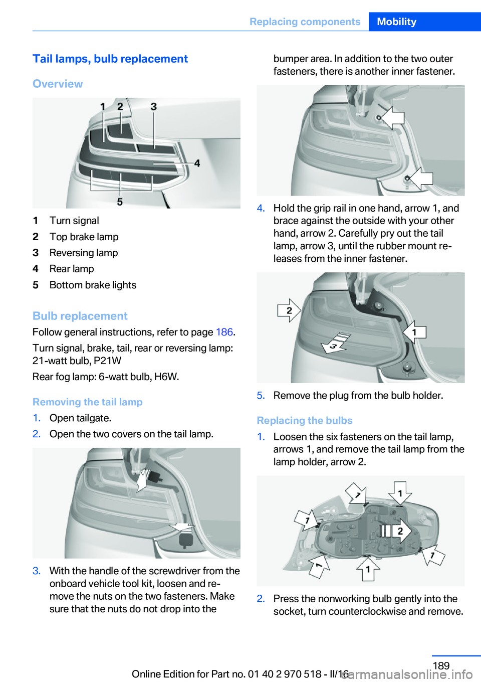
Overview1Turn signal2Top brake lamp3Reversing lamp4Rear lamp5Bottom brake lights
Bulb replacement Follow general instructions, refer to page 186.
Turn signal, brake, tail, rear or reversing lamp:
21-watt bulb, P21W
Rear fog lamp: 6-watt bulb, H6W.
Removing the tail lamp
1.Open tailgate.2.Open the two covers on the tail lamp.3.With the handle of the screwdriver from the
onboard vehicle tool kit, loosen and re‐
move the nuts on the two fasteners. Make
sure that the nuts do not drop into thebumper area. In addition to the two outer
fasteners, there is another inner fastener.4.Hold the grip rail in one hand, arrow 1, and
brace against the outside with your other
hand, arrow 2. Carefully pry out the tail
lamp, arrow 3, until the rubber mount re‐
leases from the inner fastener.5.Remove the plug from the bulb holder.
Replacing the bulbs
1.Loosen the six fasteners on the tail lamp,
arrows 1, and remove the tail lamp from the
lamp holder, arrow 2.2.Press the nonworking bulb gently into the
socket, turn counterclockwise and remove.Seite 189Replacing componentsMobility189
Online Edition for Part no. 01 40 2 970 518 - II/16
Page 190 of 220

3.Proceed in the reverse order to insert the
new bulb and attach the bulb holder to the
tail lamp. Make sure that the bulb holder
engages in all fasteners.
Installing the tail lamp
1.Connect the plug to the bulb holder.2.Insert the tail lamp straight in and press it
in, arrow 1, until the rubber mount latches
in the inner fastener. Make sure when in‐
serting the tail lamp that the rubber lip, ar‐
row 2, on the top side of the tail lamp does
not fold over. Screw on the two nuts, ar‐
row 3, and close covers.
Central brake lamp and license plate
lamp
Follow general instructions, refer to page 186.
These lights are made using LED technology.
In the case of a malfunction, contact a dealer’s
service center or another qualified service cen‐
ter or repair shop.
Changing wheels/tires General information
When sealants are used, an immediate wheel
change when there is a loss of tire inflation
pressure in the event of a flat tire is unneces‐
sary.
No spare tire is provided with your vehicle.
If needed, the tools for changing wheels are
available as accessories from a dealer’s service
center or another qualified service center or re‐
pair shop.
Jacking points for the vehicle jack
The jacking points for the vehicle jack are lo‐
cated at the positions shown.
Vehicle battery Maintenance
The battery is maintenance-free.
The added amount of acid is sufficient for the
service life of the battery.
More information about the battery can be re‐
quested from a dealer’s service center or an‐
other qualified service center or repair shop.
Battery replacement ATTENTION
Vehicle batteries that are not compatible
can damage vehicle systems and impair vehi‐
cle functions. There is a risk of personal and
property damage. Only vehicle batteries that
are compatible with your vehicle type should
be installed in your vehicle. Information on
compatible vehicle batteries is available at your
dealer’s service center.◀
After a battery replacement, the manufacturer
of your vehicle recommends that the vehicle
battery be registered on the vehicle by a
dealer’s service center or another qualified
service center or repair shop to ensure that all
comfort features are fully available and that any
Seite 190MobilityReplacing components190
Online Edition for Part no. 01 40 2 970 518 - II/16
Page 193 of 220
Breakdown assistanceVehicle features and options
This chapter describes all standard, country-
specific and optional features offered with the
series. It also describes features that are not
necessarily available in your car, e. g., due to
the selected options or country versions. This
also applies to safety-related functions and
systems. The respectively applicable country
provisions must be observed when using the
respective features and systems.
Hazard warning flashers
The button is located in the center console.
Intelligent emergency call
The concept In case of an emergency, an Emergency Re‐
quest can be made through this system.
General information
Only press the SOS button in an emergency.
For technical reasons, the Emergency Request
cannot be guaranteed under unfavorable con‐
ditions.
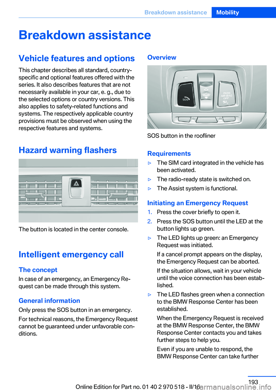
Overview
SOS button in the roofliner
Requirements
▷The SIM card integrated in the vehicle has
been activated.▷The radio-ready state is switched on.▷The Assist system is functional.
Initiating an Emergency Request
1.Press the cover briefly to open it.2.Press the SOS button until the LED at the
button lights up green.▷The LED lights up green: an Emergency
Request was initiated.
If a cancel prompt appears on the display,
the Emergency Request can be aborted.
If the situation allows, wait in your vehicle
until the voice connection has been estab‐
lished.▷The LED flashes green when a connection
to the BMW Response Center has been
established.
When the Emergency Request is received
at the BMW Response Center, the BMW
Response Center contacts you and takes
further steps to help you.
Even if you are unable to respond, the
BMW Response Center can take furtherSeite 193Breakdown assistanceMobility193
Online Edition for Part no. 01 40 2 970 518 - II/16
Page 196 of 220

corresponding engine or body ground of
the vehicle to be started.
Starting the engine
Never use spray fluids to start the engine.
1.Start the engine of the assisting vehicle
and let it run for several minutes at an in‐
creased idle speed.2.Start the engine of the vehicle that is to be
started in the usual way.
If the first starting attempt is not success‐
ful, wait a few minutes before making an‐
other attempt in order to allow the dis‐
charged battery to recharge.3.Let both engines run for several minutes.4.Disconnect the jumper cables in the re‐
verse order.
Check the battery and recharge if needed.
Tow-starting and towing Information WARNING
Due to system limits, individual functions
can malfunction during tow-starting/towing
with the Intelligent Safety systems activated,
e.g., approach control warning with light brak‐
ing function. There is risk of an accident.
Switch all Intelligent Safety systems off prior to
tow-starting/towing.◀
Manual transmission
Gearshift lever in neutral position.
Towing Follow the following instructions:
▷Make sure that the ignition is switched on;
otherwise, the low beams, tail lamps, turn
signals, and wipers may be unavailable.▷Do not tow the vehicle with the rear axle
tilted, as the front wheels could turn.▷When the engine is stopped, there is no
power assist. Consequently, more force
needs to be applied when braking and
steering.▷Larger steering wheel movements are re‐
quired.▷The towing vehicle must not be lighter
than the vehicle being towed; otherwise,
it will not be possible to control the vehi‐
cle's response.▷Do not exceed a towing speed of
30 mph/50 km/h.▷Do not exceed a towing distance of
30 miles/50 km.
Tow truck
With rear-wheel drive
Your vehicle should be transported with a tow
truck with a so-called lift bar or on a flat bed.
ATTENTION
When lifting the vehicle by the tow fitting
or body and chassis parts; damage can occur
on vehicle parts. There is a risk of damage to
property. Lift vehicle using suitable means.◀
M double-clutch transmission:
transporting the vehicle
Information The vehicle is not permitted to be towed.
Seite 196MobilityBreakdown assistance196
Online Edition for Part no. 01 40 2 970 518 - II/16
Page 197 of 220
ATTENTION
The vehicle can be damaged when tow‐
ing the vehicle with a single lifted axle. There is
a risk of damage to property. The vehicle
should only be transported on a loading plat‐
form.◀
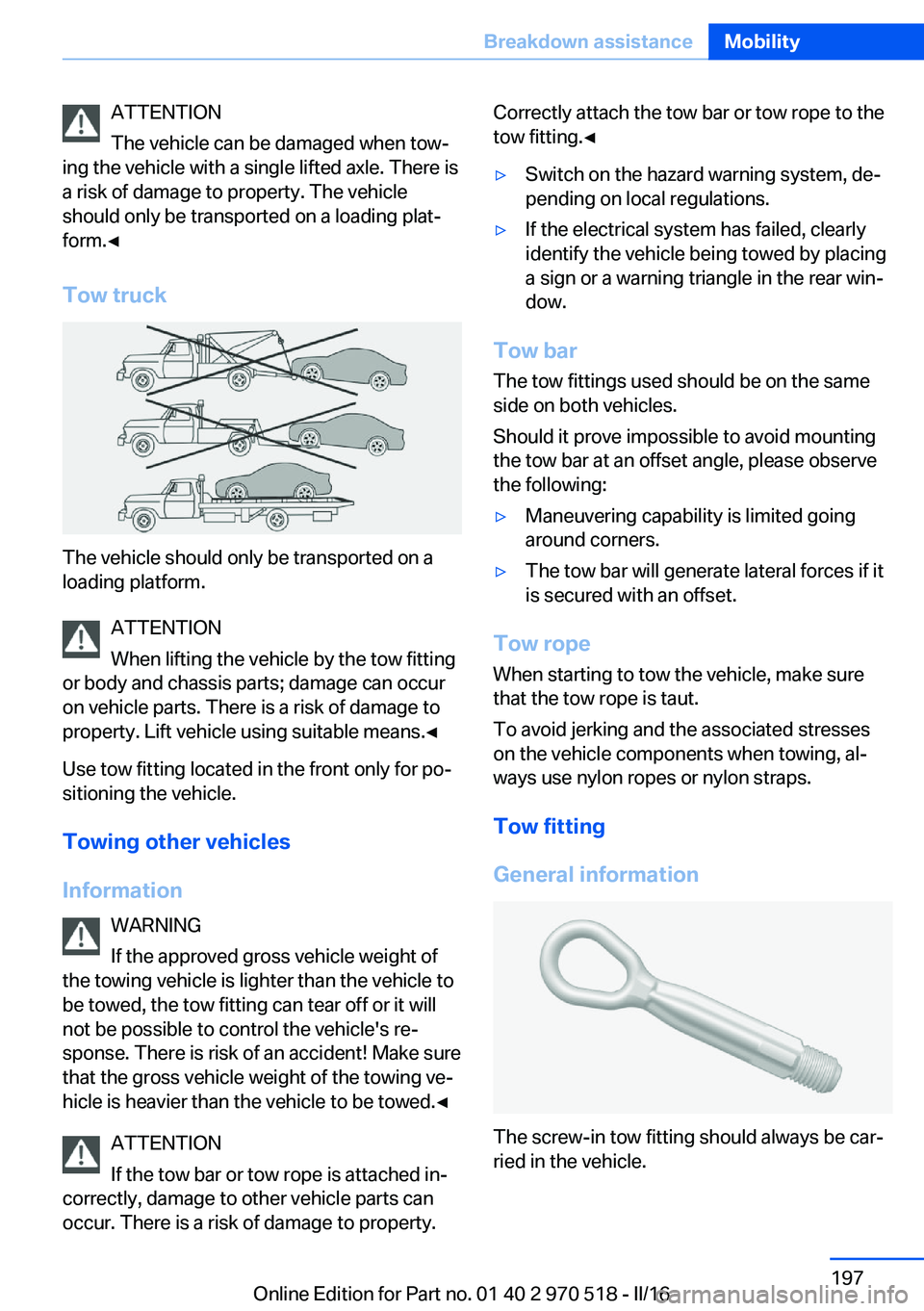
Tow truck
The vehicle should only be transported on a
loading platform.
ATTENTION
When lifting the vehicle by the tow fitting
or body and chassis parts; damage can occur
on vehicle parts. There is a risk of damage to
property. Lift vehicle using suitable means.◀
Use tow fitting located in the front only for po‐
sitioning the vehicle.
Towing other vehicles
Information WARNING
If the approved gross vehicle weight of
the towing vehicle is lighter than the vehicle to be towed, the tow fitting can tear off or it will
not be possible to control the vehicle's re‐
sponse. There is risk of an accident! Make sure
that the gross vehicle weight of the towing ve‐
hicle is heavier than the vehicle to be towed.◀
ATTENTION
If the tow bar or tow rope is attached in‐
correctly, damage to other vehicle parts can
occur. There is a risk of damage to property.
Correctly attach the tow bar or tow rope to the
tow fitting.◀▷Switch on the hazard warning system, de‐
pending on local regulations.▷If the electrical system has failed, clearly
identify the vehicle being towed by placing
a sign or a warning triangle in the rear win‐
dow.
Tow bar
The tow fittings used should be on the same
side on both vehicles.
Should it prove impossible to avoid mounting
the tow bar at an offset angle, please observe
the following:
▷Maneuvering capability is limited going
around corners.▷The tow bar will generate lateral forces if it
is secured with an offset.
Tow rope
When starting to tow the vehicle, make sure
that the tow rope is taut.
To avoid jerking and the associated stresses
on the vehicle components when towing, al‐
ways use nylon ropes or nylon straps.
Tow fitting
General information
The screw-in tow fitting should always be car‐
ried in the vehicle.
Seite 197Breakdown assistanceMobility197
Online Edition for Part no. 01 40 2 970 518 - II/16