Page 216 of 255
Replacing componentsVehicle features and optionsThis chapter describes all standard, country-
specific and optional features offered with the
series. It also describes features that are not
necessarily available in your car, e. g., due to
the selected options or country versions. This
also applies to safety-related functions and
systems. The respectively applicable country
provisions must be observed when using the
respective features and systems.
Onboard vehicle tool kit
The onboard vehicle tool kit is located under
the cargo floor panel. Lift to open the slim
cover.
Wiper blade replacement
Note Do not fold down the wipers without
wiper blades
Do not fold down the wipers if wiper blades
have not been installed; this may damage the
windshield.◀
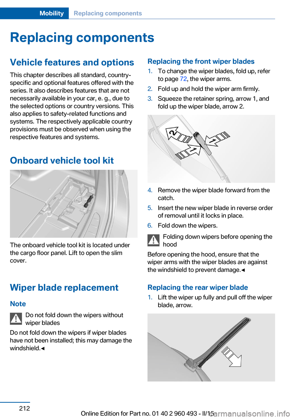
Replacing the front wiper blades1.To change the wiper blades, fold up, refer
to page 72, the wiper arms.2.Fold up and hold the wiper arm firmly.3.Squeeze the retainer spring, arrow 1, and
fold up the wiper blade, arrow 2.4.Remove the wiper blade forward from the
catch.5.Insert the new wiper blade in reverse order
of removal until it locks in place.6.Fold down the wipers.
Folding down wipers before opening the hood
Before opening the hood, ensure that the
wiper arms with the wiper blades are against
the windshield to prevent damage.◀
Replacing the rear wiper blade
1.Lift the wiper up fully and pull off the wiper
blade, arrow.Seite 212MobilityReplacing components212
Online Edition for Part no. 01 40 2 960 493 - II/15
Page 218 of 255
Front lights, bulb replacement
Halogen headlights
Headlights1Parking lights2High beams/headlight flasher3Low beams4Turn signal5Daytime running lights
Accessing the turn signals and low beams
Follow general instructions, refer to page 213.
In the wheel house, loosen the two brackets
and remove the cover.
Turn signal
21-watt bulb, PY21W1.If necessary, pull the inside trim of the
wheel house slightly inward. Turn the bulb
holder counterclockwise and remove.2.Press the bulb gently into the socket, turn
counterclockwise and remove.3.Install the new bulb and bulb holder in re‐
verse order of removal.4.Attach the cover to the wheel house.Seite 214MobilityReplacing components214
Online Edition for Part no. 01 40 2 960 493 - II/15
Page 219 of 255
Low beams
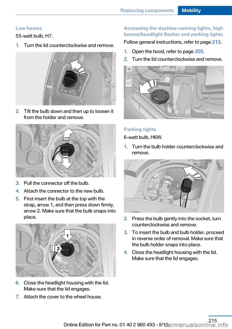
55-watt bulb, H7.1.Turn the lid counterclockwise and remove.2.Tilt the bulb down and then up to loosen it
from the holder and remove.3.Pull the connector off the bulb.4.Attach the connector to the new bulb.5.First insert the bulb at the top with the
strap, arrow 1, and then press down firmly,
arrow 2. Make sure that the bulb snaps into
place.6.Close the headlight housing with the lid.
Make sure that the lid engages.7.Attach the cover to the wheel house.Accessing the daytime running lights, high
beams/headlight flasher and parking lights
Follow general instructions, refer to page 213.1.Open the hood, refer to page 205.2.Turn the lid counterclockwise and remove.
Parking lights
6-watt bulb, H6W.
1.Turn the bulb holder counterclockwise and
remove.2.Press the bulb gently into the socket, turn
counterclockwise and remove.3.To insert the bulb and bulb holder, proceed
in reverse order of removal. Make sure that
the bulb holder snaps into place.4.Close the headlight housing with the lid.
Make sure that the lid engages.Seite 215Replacing componentsMobility215
Online Edition for Part no. 01 40 2 960 493 - II/15
Page 221 of 255
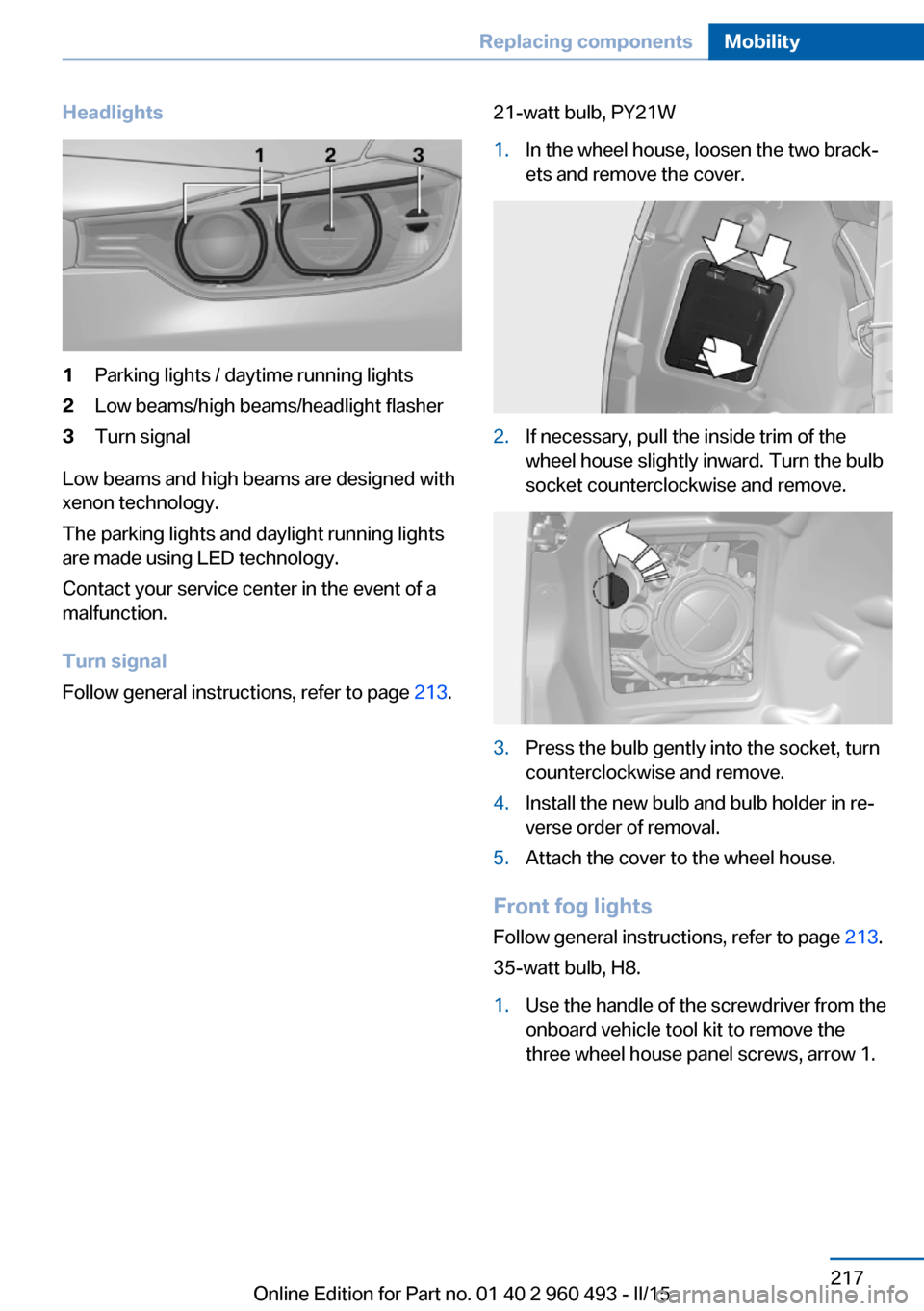
Headlights1Parking lights / daytime running lights2Low beams/high beams/headlight flasher3Turn signal
Low beams and high beams are designed with
xenon technology.
The parking lights and daylight running lights
are made using LED technology.
Contact your service center in the event of a
malfunction.
Turn signal
Follow general instructions, refer to page 213.
21-watt bulb, PY21W1.In the wheel house, loosen the two brack‐
ets and remove the cover.2.If necessary, pull the inside trim of the
wheel house slightly inward. Turn the bulb
socket counterclockwise and remove.3.Press the bulb gently into the socket, turn
counterclockwise and remove.4.Install the new bulb and bulb holder in re‐
verse order of removal.5.Attach the cover to the wheel house.
Front fog lights
Follow general instructions, refer to page 213.
35-watt bulb, H8.
1.Use the handle of the screwdriver from the
onboard vehicle tool kit to remove the
three wheel house panel screws, arrow 1.Seite 217Replacing componentsMobility217
Online Edition for Part no. 01 40 2 960 493 - II/15
Page 222 of 255
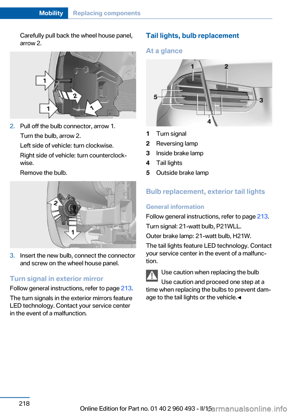
Carefully pull back the wheel house panel,
arrow 2.2.Pull off the bulb connector, arrow 1.
Turn the bulb, arrow 2.
Left side of vehicle: turn clockwise.
Right side of vehicle: turn counterclock‐
wise.
Remove the bulb.3.Insert the new bulb, connect the connector
and screw on the wheel house panel.
Turn signal in exterior mirror
Follow general instructions, refer to page 213.
The turn signals in the exterior mirrors feature
LED technology. Contact your service center
in the event of a malfunction.
Tail lights, bulb replacement
At a glance1Turn signal2Reversing lamp3Inside brake lamp4Tail lights5Outside brake lamp
Bulb replacement, exterior tail lights General information
Follow general instructions, refer to page 213.
Turn signal: 21-watt bulb, P21WLL.
Outer brake lamp: 21-watt bulb, H21W.
The tail lights feature LED technology. Contact
your service center in the event of a malfunc‐
tion.
Use caution when replacing the bulb
Use caution and proceed one step at a
time when replacing the bulbs to prevent dam‐
age to the tail lights or the vehicle.◀
Seite 218MobilityReplacing components218
Online Edition for Part no. 01 40 2 960 493 - II/15
Page 223 of 255
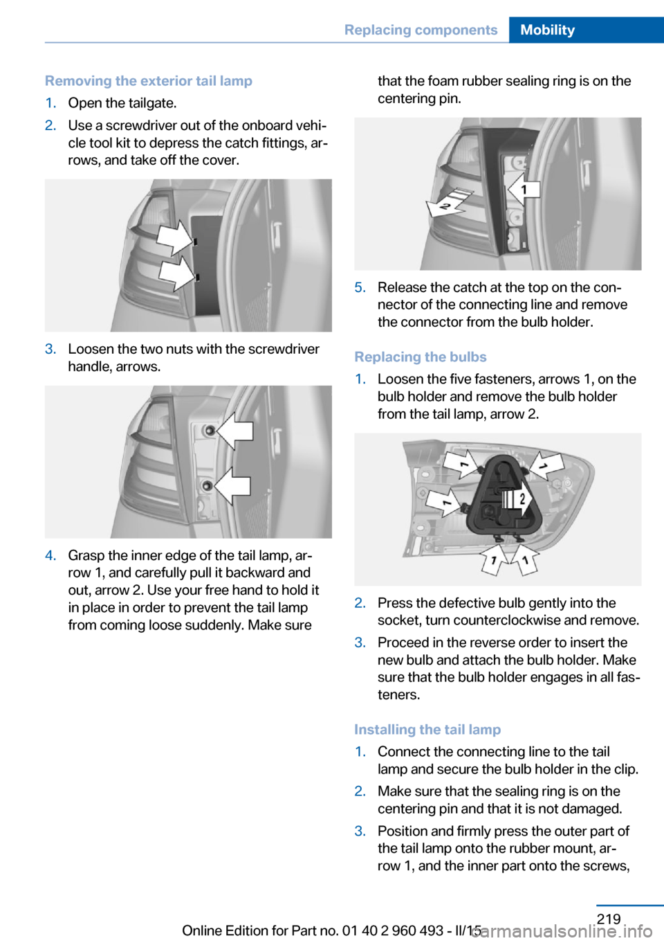
Removing the exterior tail lamp1.Open the tailgate.2.Use a screwdriver out of the onboard vehi‐
cle tool kit to depress the catch fittings, ar‐
rows, and take off the cover.3.Loosen the two nuts with the screwdriver
handle, arrows.4.Grasp the inner edge of the tail lamp, ar‐
row 1, and carefully pull it backward and
out, arrow 2. Use your free hand to hold it
in place in order to prevent the tail lamp
from coming loose suddenly. Make surethat the foam rubber sealing ring is on the
centering pin.5.Release the catch at the top on the con‐
nector of the connecting line and remove
the connector from the bulb holder.
Replacing the bulbs
1.Loosen the five fasteners, arrows 1, on the
bulb holder and remove the bulb holder
from the tail lamp, arrow 2.2.Press the defective bulb gently into the
socket, turn counterclockwise and remove.3.Proceed in the reverse order to insert the
new bulb and attach the bulb holder. Make
sure that the bulb holder engages in all fas‐
teners.
Installing the tail lamp
1.Connect the connecting line to the tail
lamp and secure the bulb holder in the clip.2.Make sure that the sealing ring is on the
centering pin and that it is not damaged.3.Position and firmly press the outer part of
the tail lamp onto the rubber mount, ar‐
row 1, and the inner part onto the screws,Seite 219Replacing componentsMobility219
Online Edition for Part no. 01 40 2 960 493 - II/15
Page 224 of 255
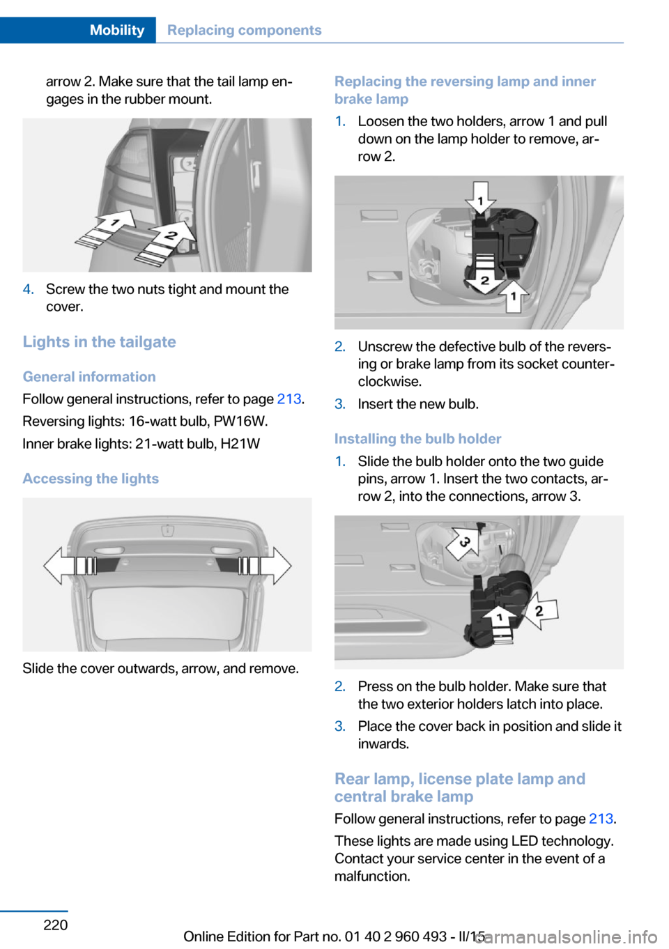
arrow 2. Make sure that the tail lamp en‐
gages in the rubber mount.4.Screw the two nuts tight and mount the
cover.
Lights in the tailgate
General information
Follow general instructions, refer to page 213.
Reversing lights: 16-watt bulb, PW16W.
Inner brake lights: 21-watt bulb, H21W
Accessing the lights
Slide the cover outwards, arrow, and remove.
Replacing the reversing lamp and inner
brake lamp1.Loosen the two holders, arrow 1 and pull
down on the lamp holder to remove, ar‐
row 2.2.Unscrew the defective bulb of the revers‐
ing or brake lamp from its socket counter‐
clockwise.3.Insert the new bulb.
Installing the bulb holder
1.Slide the bulb holder onto the two guide
pins, arrow 1. Insert the two contacts, ar‐
row 2, into the connections, arrow 3.2.Press on the bulb holder. Make sure that
the two exterior holders latch into place.3.Place the cover back in position and slide it
inwards.
Rear lamp, license plate lamp and
central brake lamp
Follow general instructions, refer to page 213.
These lights are made using LED technology.
Contact your service center in the event of a
malfunction.
Seite 220MobilityReplacing components220
Online Edition for Part no. 01 40 2 960 493 - II/15
Page 231 of 255
Tow-starting and towingNote Tow-starting and towing
For tow-starting or towing, switch off the
Intelligent Safety systems; otherwise malfunc‐
tions of the individual braking systems might
lead to accidents.◀
Manual transmission Gearshift lever in neutral position.
Towing Follow the towing instructions
Follow all towing instructions; otherwise,
vehicle damage or accidents may occur.◀▷Make sure that the ignition is switched on;
otherwise, the low beams, tail lights, turn
signals, and wipers may be unavailable.▷Do not tow the vehicle with the rear axle
tilted, as the front wheels could turn.▷When the engine is stopped, there is no
power assist. Consequently, more force
needs to be applied when braking and
steering.▷Larger steering wheel movements are re‐
quired.▷The towing vehicle must not be lighter
than the vehicle being towed; otherwise,
it will not be possible to control the vehi‐
cle's response.Tow truck
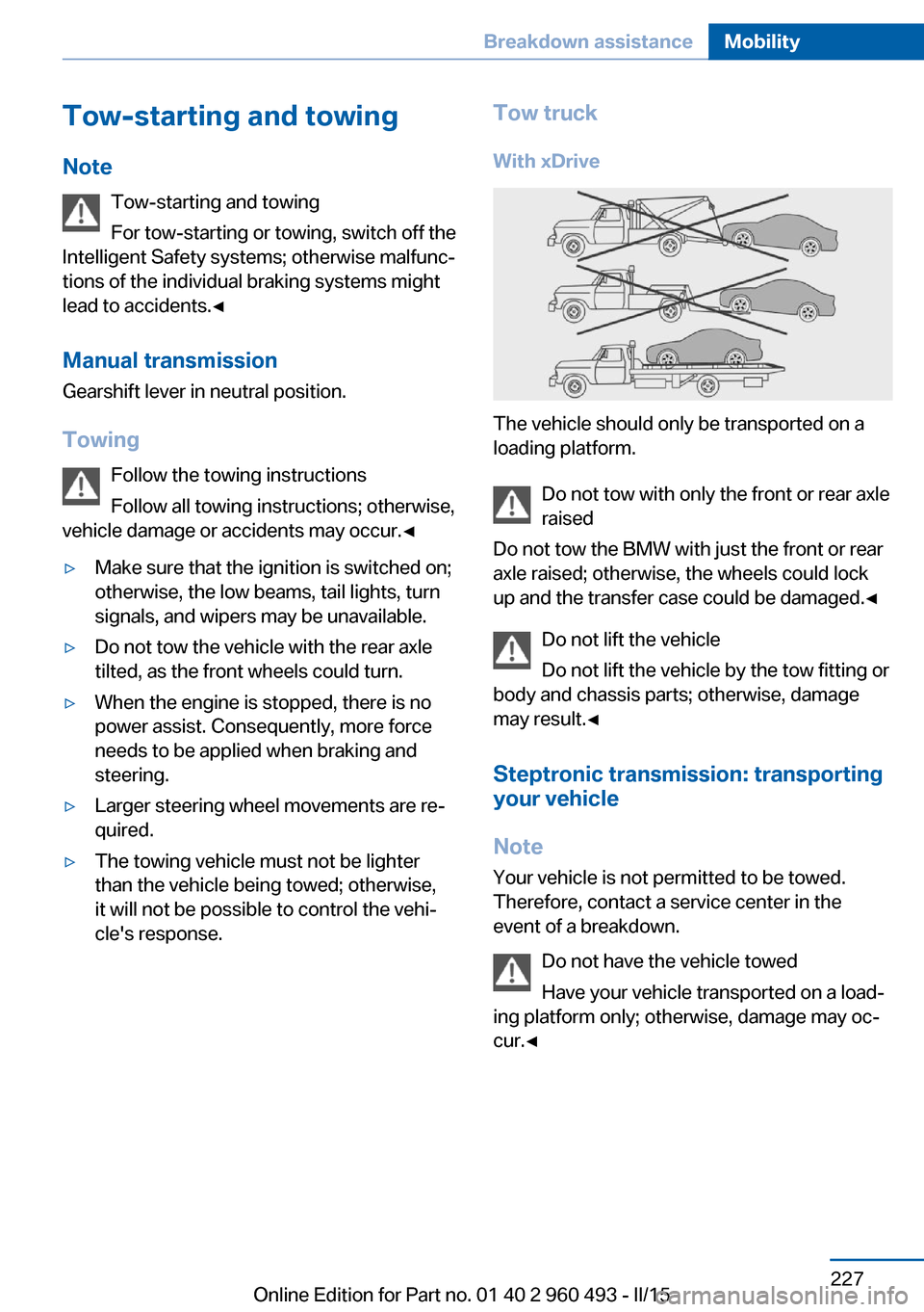
With xDrive
The vehicle should only be transported on a
loading platform.
Do not tow with only the front or rear axle
raised
Do not tow the BMW with just the front or rear
axle raised; otherwise, the wheels could lock
up and the transfer case could be damaged.◀
Do not lift the vehicle
Do not lift the vehicle by the tow fitting or
body and chassis parts; otherwise, damage
may result.◀
Steptronic transmission: transporting
your vehicle
Note Your vehicle is not permitted to be towed.
Therefore, contact a service center in the
event of a breakdown.
Do not have the vehicle towedHave your vehicle transported on a load‐
ing platform only; otherwise, damage may oc‐
cur.◀
Seite 227Breakdown assistanceMobility227
Online Edition for Part no. 01 40 2 960 493 - II/15