2016 BMW 3 SERIES SPORTS WAGON point
[x] Cancel search: pointPage 98 of 255
Headlight courtesy delay featureThe low beams stay lit for a short while if the
headlight flasher is switched on after the radio-
ready state is switched off.
Setting the duration
On the Control Display:1."Settings"2."Lighting"3."Pathway lighting:"4.Set length of time.
Settings are stored for the profile currently in
use.
Automatic headlight control
Position of switch
: the low beams are acti‐
vated and off automatically, e.g., in tunnels, in
twilight or if there is precipitation. The indicator
lamp in the instrument cluster lights up.
When emerging from a tunnel during the day,
the low beams are not switched off immedi‐
ately but instead only after approx. 2 minutes.
A blue sky with the sun low on the horizon can
cause the lights to be switched on.
The low beams always stay on when the fog
lights are activated.
Personal responsibility
The automatic headlight control cannot
serve as a substitute for your personal judg‐
ment in determining when to turn the lights on
in response to ambient lighting conditions.
E. g. the sensors are unable to detect fog or
hazy weather. To avoid safety risks under
these conditions, you should always switch on
the lights manually.◀
Daytime running lights With the ignition switched on, the daytime run‐
ning lights light up in position
, or
. After the ignition is switched off, the park‐
ing lights light up in position
.
Activating/deactivating
In some countries, daytime running lights are
mandatory, so it may not be possible to deacti‐
vate the daytime running lights.
On the Control Display:1."Settings"2."Lighting"3."Daytime running lamps"
Settings are stored for the profile currently in
use.
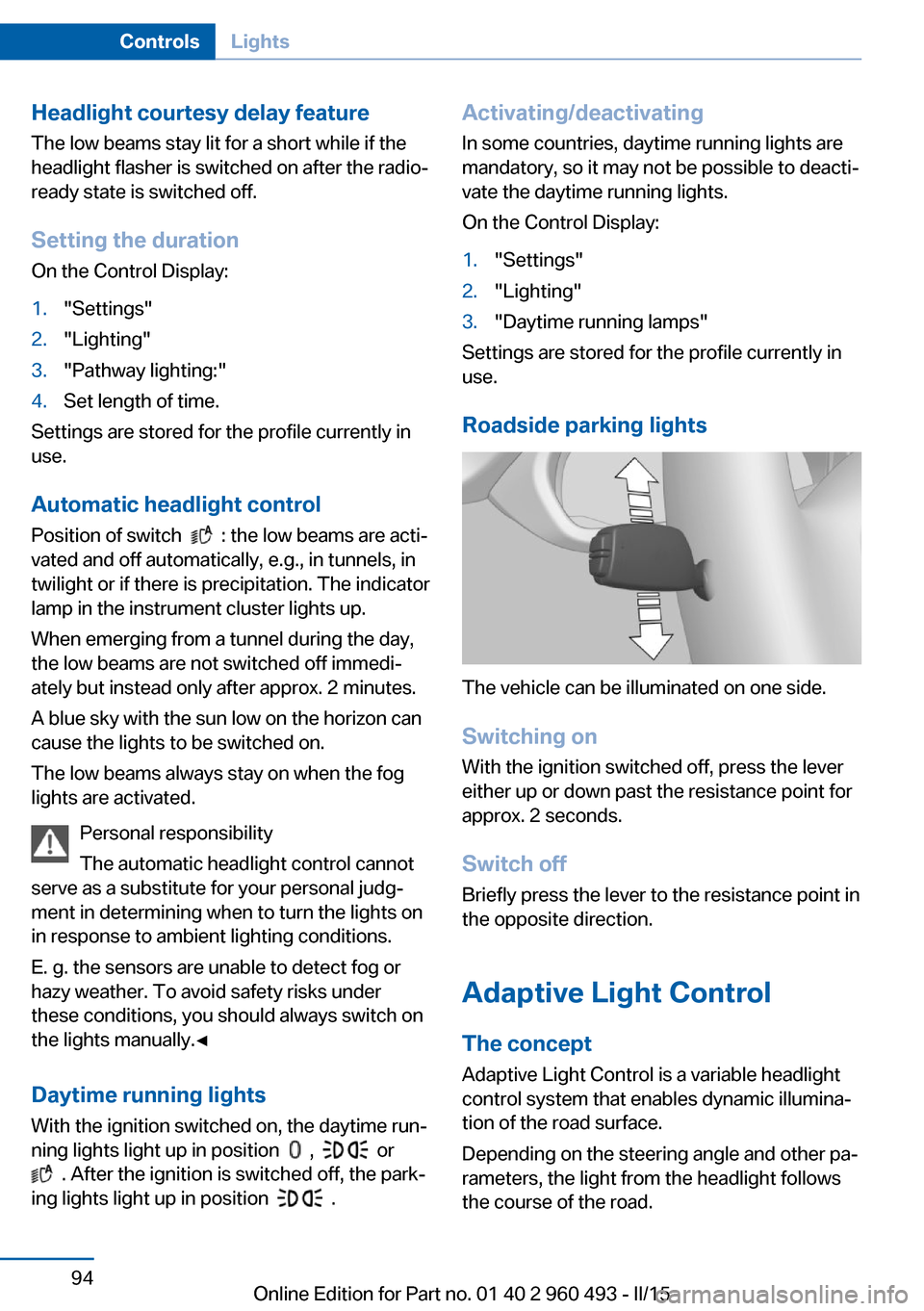
Roadside parking lights
The vehicle can be illuminated on one side.
Switching on With the ignition switched off, press the lever
either up or down past the resistance point for
approx. 2 seconds.
Switch off Briefly press the lever to the resistance point in
the opposite direction.
Adaptive Light Control The concept
Adaptive Light Control is a variable headlight
control system that enables dynamic illumina‐
tion of the road surface.
Depending on the steering angle and other pa‐ rameters, the light from the headlight follows
the course of the road.
Seite 94ControlsLights94
Online Edition for Part no. 01 40 2 960 493 - II/15
Page 131 of 255
InterruptingWhen active, press the button.
If interrupting the system while stationary,
press on the brake pedal at the same time.
The system is automatically interrupted in the
following situations:▷When the brakes are applied.▷When selector lever position D is disen‐
gaged.▷When DTC Dynamic Traction Control is
activated or DSC is deactivated.▷When DSC is actively controlling stability.▷When SPORT+ is activated with Driving
Dynamics Control.▷If the safety belt and the driver's door are
opened while the vehicle is standing still.▷If the system has not detected objects for
an extended period, e.g., on a road with
very little traffic without curb or shoulder
markings.▷If the detection range of the radar is dis‐
rupted, e.g., by dirt or heavy fog.
Maintaining, storing, and changing the
speed
Hints Adjusting the desired speedModify desired speed to road conditions
and be ready to brake at all times; otherwise,
there is the risk of an accident.◀
Differences in speed
Large differences in speed relative to ve‐
hicles ahead of the vehicle cannot be compen‐
sated by the system for example in the follow‐
ing situations:
▷When fast approaching a slowly moving
vehicle.▷When another vehicle suddenly swerves
into the wrong lane.◀Maintaining/storing the speed
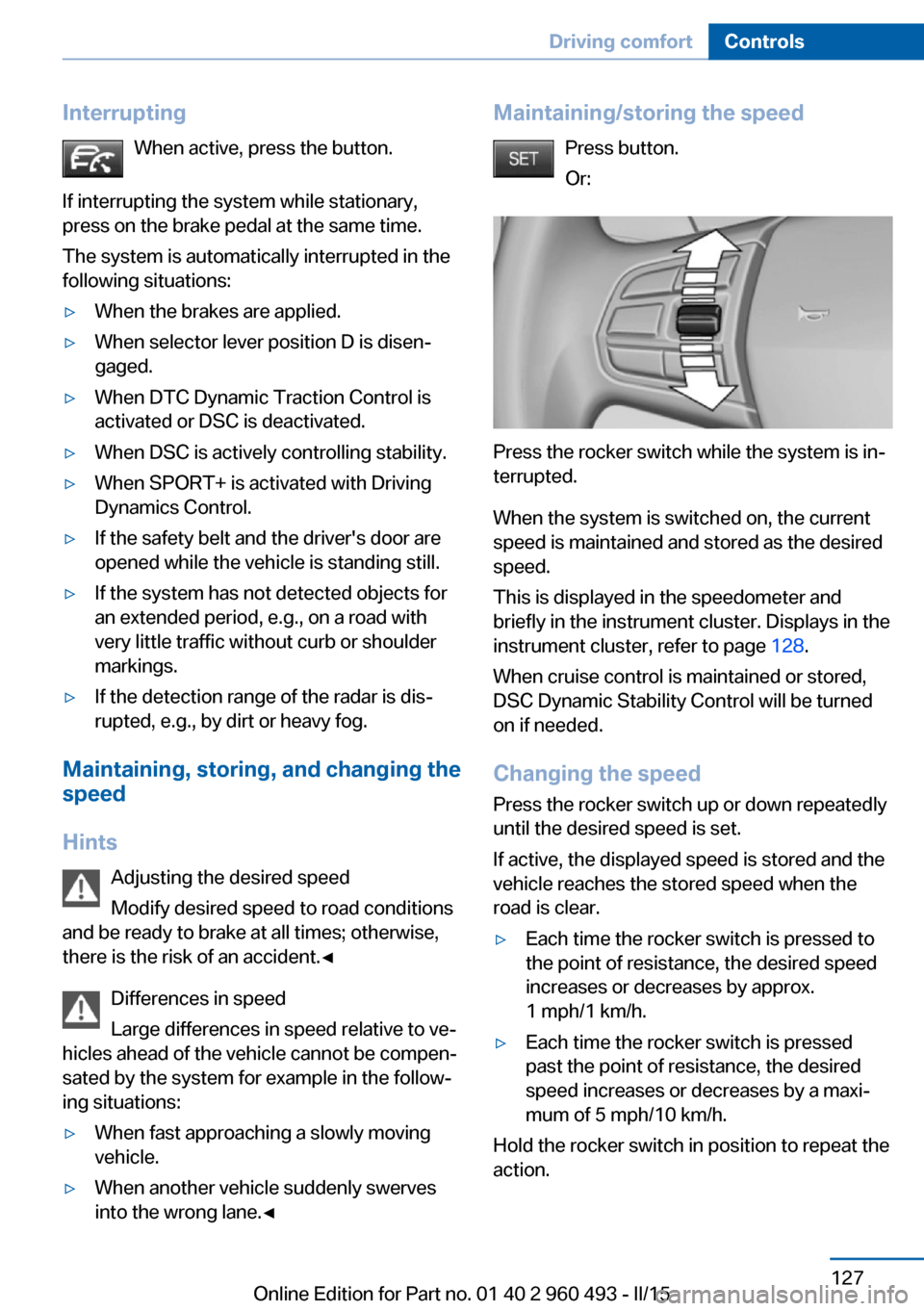
Press button.
Or:
Press the rocker switch while the system is in‐
terrupted.
When the system is switched on, the current
speed is maintained and stored as the desired
speed.
This is displayed in the speedometer and
briefly in the instrument cluster. Displays in the
instrument cluster, refer to page 128.
When cruise control is maintained or stored,
DSC Dynamic Stability Control will be turned
on if needed.
Changing the speed
Press the rocker switch up or down repeatedly
until the desired speed is set.
If active, the displayed speed is stored and the vehicle reaches the stored speed when the
road is clear.
▷Each time the rocker switch is pressed to
the point of resistance, the desired speed
increases or decreases by approx.
1 mph/1 km/h.▷Each time the rocker switch is pressed
past the point of resistance, the desired
speed increases or decreases by a maxi‐
mum of 5 mph/10 km/h.
Hold the rocker switch in position to repeat the
action.
Seite 127Driving comfortControls127
Online Edition for Part no. 01 40 2 960 493 - II/15
Page 137 of 255
When cruise control is maintained or stored,
DSC Dynamic Stability Control will be turned
on if needed.
Changing the speed
Press the rocker switch up or down repeatedly
until the desired speed is set.
If active, the displayed speed is stored and the
vehicle reaches the stored speed when the
road is clear.▷Each time the rocker switch is pressed to
the point of resistance, the desired speed
increases or decreases by approx.
1 mph/1 km/h.▷Each time the rocker switch is pressed
past the point of resistance, the desired
speed increases or decreases by a maxi‐
mum of 5 mph/10 km/h.
The maximum speed that can be set de‐
pends on the vehicle.▷Pressing the rocker switch to the resist‐
ance point and holding it accelerates or de‐
celerates the vehicle without requiring
pressure on the accelerator pedal.
After the rocker switch is released, the ve‐
hicle maintains its final speed. Pressing the
switch beyond the resistance point causes
the vehicle to accelerate more rapidly.
Resuming the desired speed
Press button.
The stored speed is reached and maintained. Displays in the instrument cluster
Indicator lamp Depending on how the vehicle is equip‐
ped, the indicator lamp in the instru‐
ment cluster indicates whether the sys‐
tem is switched on.
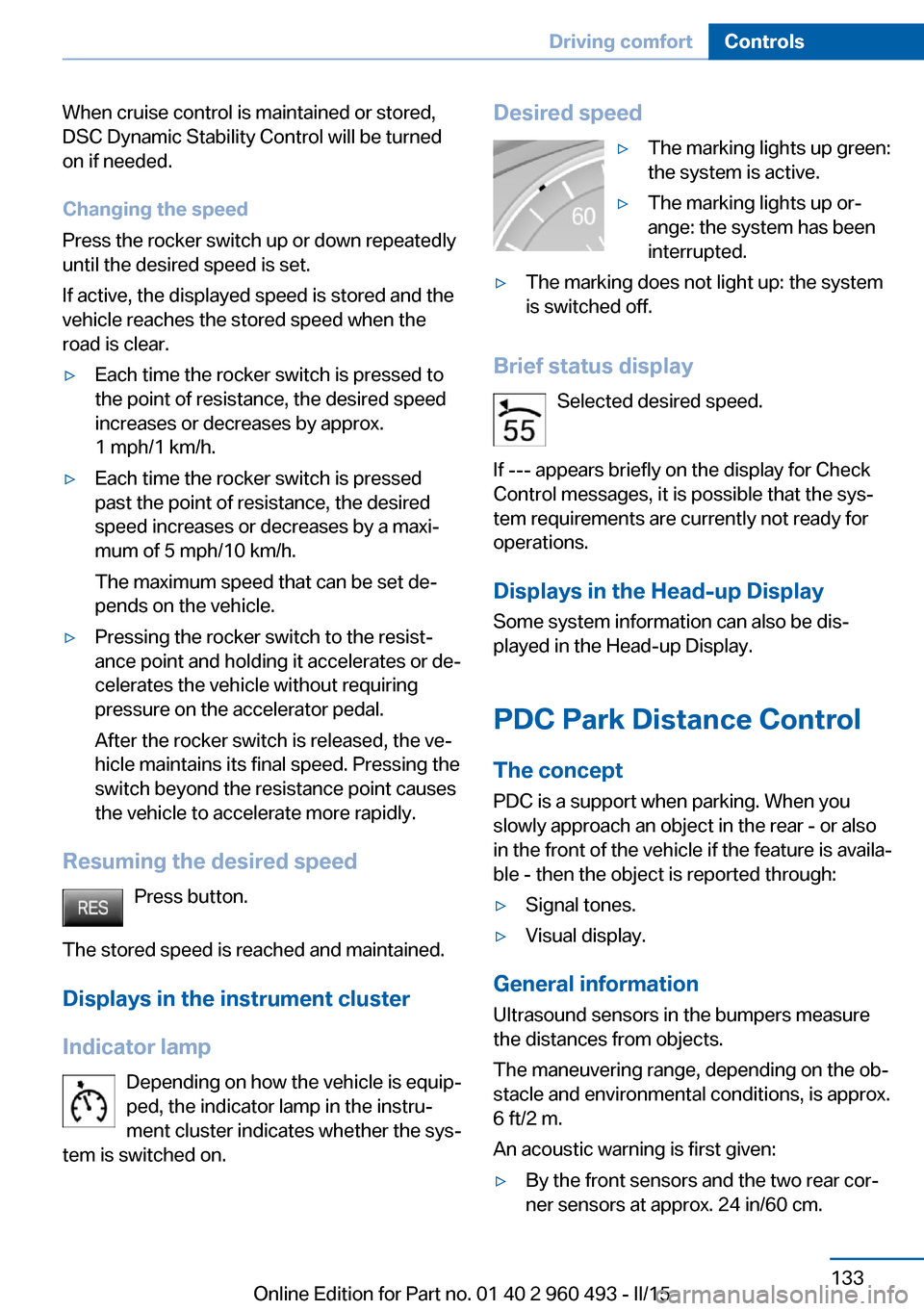
Desired speed▷The marking lights up green:
the system is active.▷The marking lights up or‐
ange: the system has been
interrupted.▷The marking does not light up: the system
is switched off.
Brief status display
Selected desired speed.
If --- appears briefly on the display for Check
Control messages, it is possible that the sys‐
tem requirements are currently not ready for
operations.
Displays in the Head-up Display Some system information can also be dis‐played in the Head-up Display.
PDC Park Distance Control
The concept PDC is a support when parking. When you
slowly approach an object in the rear - or also
in the front of the vehicle if the feature is availa‐
ble - then the object is reported through:
▷Signal tones.▷Visual display.
General information
Ultrasound sensors in the bumpers measure
the distances from objects.
The maneuvering range, depending on the ob‐
stacle and environmental conditions, is approx.
6 ft/2 m.
An acoustic warning is first given:
▷By the front sensors and the two rear cor‐
ner sensors at approx. 24 in/60 cm.Seite 133Driving comfortControls133
Online Edition for Part no. 01 40 2 960 493 - II/15
Page 142 of 255
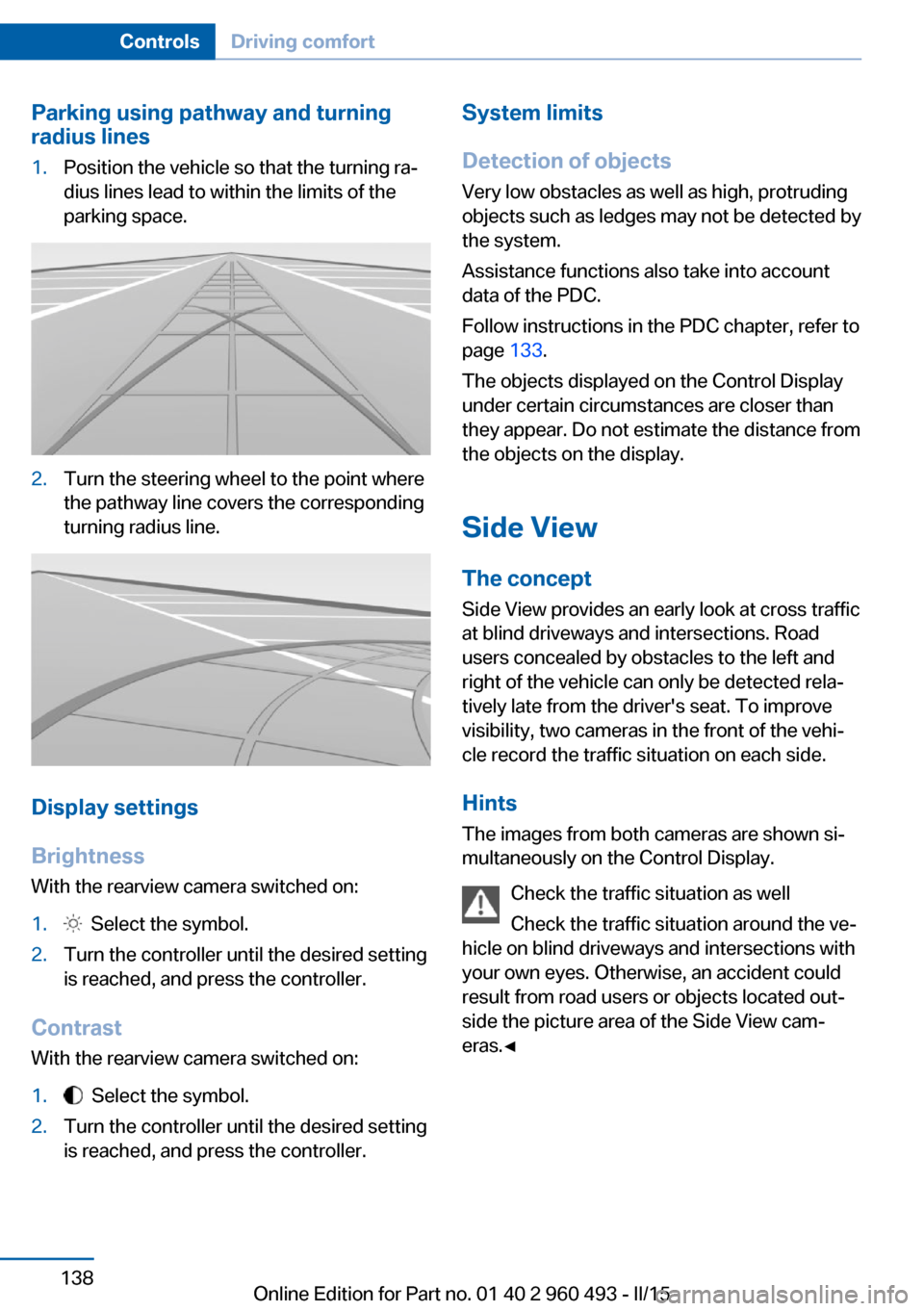
Parking using pathway and turning
radius lines1.Position the vehicle so that the turning ra‐
dius lines lead to within the limits of the
parking space.2.Turn the steering wheel to the point where
the pathway line covers the corresponding
turning radius line.
Display settings
Brightness
With the rearview camera switched on:
1. Select the symbol.2.Turn the controller until the desired setting
is reached, and press the controller.
Contrast
With the rearview camera switched on:
1. Select the symbol.2.Turn the controller until the desired setting
is reached, and press the controller.System limits
Detection of objects
Very low obstacles as well as high, protruding
objects such as ledges may not be detected by
the system.
Assistance functions also take into account
data of the PDC.
Follow instructions in the PDC chapter, refer to
page 133.
The objects displayed on the Control Display
under certain circumstances are closer than
they appear. Do not estimate the distance from
the objects on the display.
Side View The concept Side View provides an early look at cross traffic
at blind driveways and intersections. Road
users concealed by obstacles to the left and
right of the vehicle can only be detected rela‐
tively late from the driver's seat. To improve
visibility, two cameras in the front of the vehi‐
cle record the traffic situation on each side.
Hints
The images from both cameras are shown si‐
multaneously on the Control Display.
Check the traffic situation as well
Check the traffic situation around the ve‐
hicle on blind driveways and intersections with
your own eyes. Otherwise, an accident could
result from road users or objects located out‐
side the picture area of the Side View cam‐
eras.◀Seite 138ControlsDriving comfort138
Online Edition for Part no. 01 40 2 960 493 - II/15
Page 155 of 255
Defrosts windows and removes
condensation
Press button.
Ice and condensation are quickly re‐
moved from the windshield and the front side
windows.
For this purpose, point the side vents onto the
side windows as needed.
Adjust air flow with the program active.
If the windows are fogged over, you can also
switch on the cooling function or press the AUTO button to utilize the condensation sen‐
sor.
Switching the system on/off Switch off Press the left button for the minimum
speed.
Switching on
Press any button except▷Rear window defroster.▷Seat heating.
Microfilter/activated-charcoal filter
In external and recirculated air mode the mi‐
crofilter/activated charcoal filter filters dust,
pollen, and gaseous pollutants out of the air.
This filter should be replaced during scheduled
maintenance, refer to page 210, of your vehi‐
cle.
Ventilation
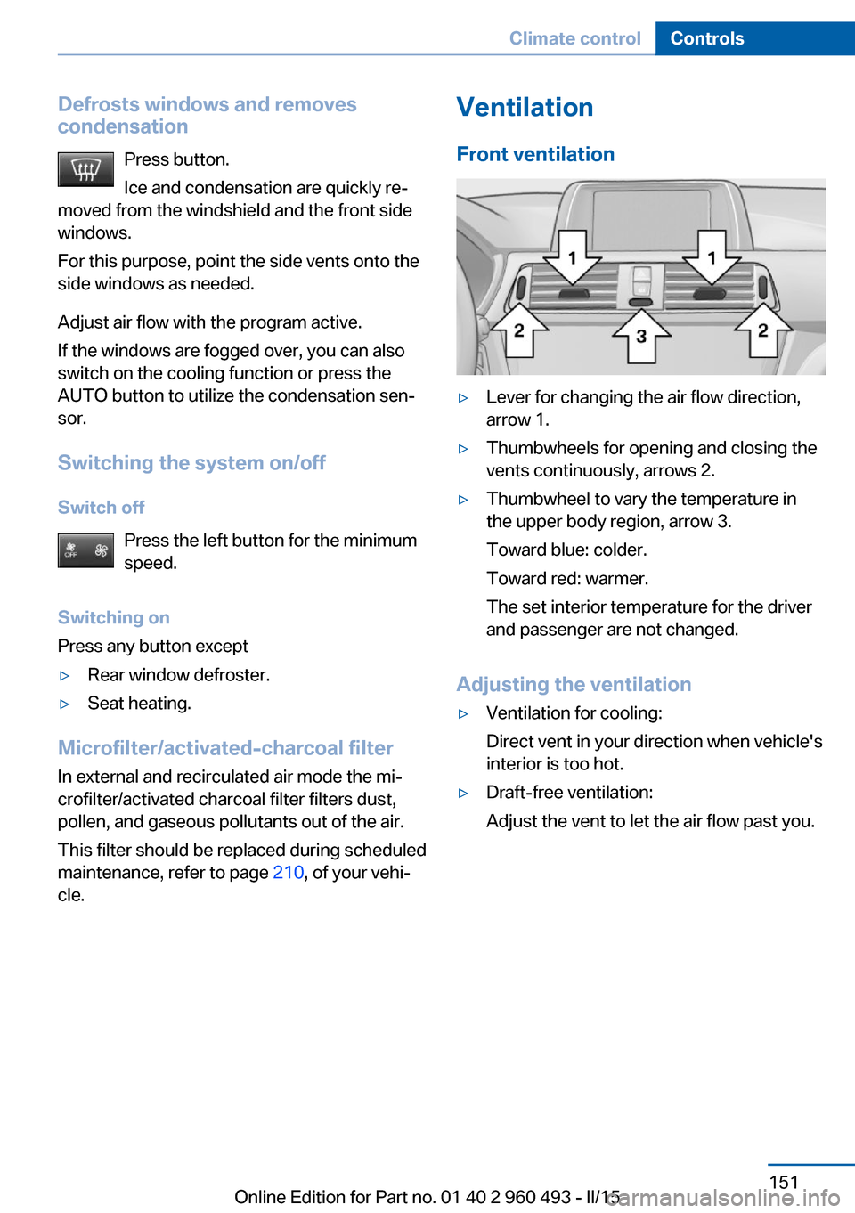
Front ventilation▷Lever for changing the air flow direction,
arrow 1.▷Thumbwheels for opening and closing the
vents continuously, arrows 2.▷Thumbwheel to vary the temperature in
the upper body region, arrow 3.
Toward blue: colder.
Toward red: warmer.
The set interior temperature for the driver
and passenger are not changed.
Adjusting the ventilation
▷Ventilation for cooling:
Direct vent in your direction when vehicle's
interior is too hot.▷Draft-free ventilation:
Adjust the vent to let the air flow past you.Seite 151Climate controlControls151
Online Edition for Part no. 01 40 2 960 493 - II/15
Page 159 of 255
4.Likewise, press and hold the button of the
desired function on the hand-held trans‐
mitter.5.Release both buttons as soon as the inte‐
rior rearview mirror LED flashes more rap‐
idly. The LED flashing faster indicates that
the button on the interior rearview mirror
has been programmed. The system can
then be controlled by the button on the in‐
terior rearview mirror.
If the LED does not flash faster after at
least 60 seconds, change the distance and
repeat the step. Several more attempts at
different distances may be necessary. Wait
at least 15 seconds between attempts.
Canada: if programming with the hand-
held transmitter was interrupted, hold
down the interior rearview mirror button
and repeatedly press and release the
hand-held transmitter button for 2 sec‐
onds.
Controls
Before operation
Before operating a system using the uni‐
versal garage door opener, ensure that there are no people, animals, or objects within the
range of movement of the remote-controlled
system; otherwise, there is a risk of injury or
damage.
Also follow the safety instructions of the hand-
held transmitter.◀
The system, such as the garage door, can be
operated using the button on the interior rear‐
view mirror while the engine is running or when
the ignition is started. To do this, hold down
the button within receiving range of the system
until the function is activated. The interior rear‐ view mirror LED stays lit while the wireless sig‐
nal is being transmitted.
Deleting stored functions Press and hold the left and right button on the
interior rearview mirror simultaneously for ap‐
proximately 20 seconds until the LED flashes
rapidly. All stored functions are deleted. The
functions cannot be deleted individually.
Digital compass
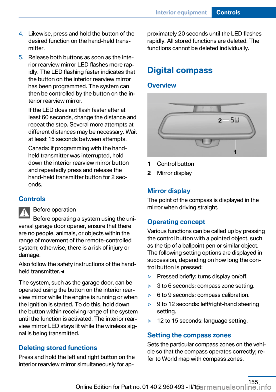
Overview1Control button2Mirror display
Mirror display
The point of the compass is displayed in the
mirror when driving straight.
Operating concept
Various functions can be called up by pressing
the control button with a pointed object, such
as the tip of a ballpoint pen or similar object.
The following setting options are displayed in
succession, depending on how long the con‐
trol button is pressed:
▷Pressed briefly: turns display on/off.▷3 to 6 seconds: compass zone setting.▷6 to 9 seconds: compass calibration.▷9 to 12 seconds: left/right-hand steering
setting.▷12 to 15 seconds: language setting.
Setting the compass zones
Sets the particular compass zones on the vehi‐
cle so that the compass operates correctly; re‐
fer to World map with compass zones.
Seite 155Interior equipmentControls155
Online Edition for Part no. 01 40 2 960 493 - II/15
Page 160 of 255
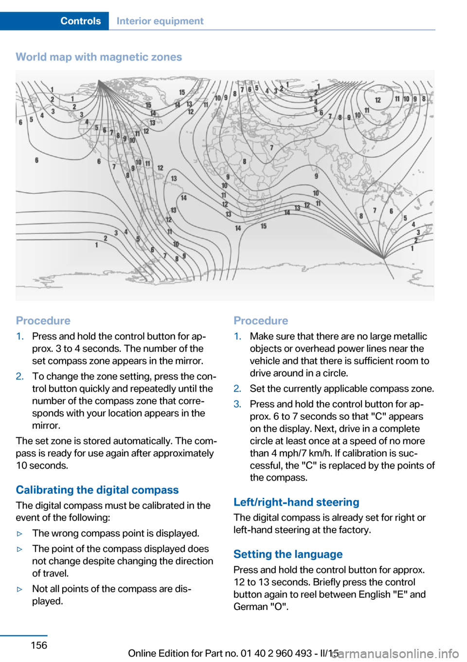
World map with magnetic zonesProcedure1.Press and hold the control button for ap‐
prox. 3 to 4 seconds. The number of the
set compass zone appears in the mirror.2.To change the zone setting, press the con‐
trol button quickly and repeatedly until the
number of the compass zone that corre‐
sponds with your location appears in the
mirror.
The set zone is stored automatically. The com‐
pass is ready for use again after approximately
10 seconds.
Calibrating the digital compass
The digital compass must be calibrated in the
event of the following:
▷The wrong compass point is displayed.▷The point of the compass displayed does
not change despite changing the direction
of travel.▷Not all points of the compass are dis‐
played.Procedure1.Make sure that there are no large metallic
objects or overhead power lines near the
vehicle and that there is sufficient room to
drive around in a circle.2.Set the currently applicable compass zone.3.Press and hold the control button for ap‐
prox. 6 to 7 seconds so that "C" appears
on the display. Next, drive in a complete
circle at least once at a speed of no more
than 4 mph/7 km/h. If calibration is suc‐
cessful, the "C" is replaced by the points of
the compass.
Left/right-hand steering
The digital compass is already set for right or
left-hand steering at the factory.
Setting the language
Press and hold the control button for approx.
12 to 13 seconds. Briefly press the control
button again to reel between English "E" and
German "O".
Seite 156ControlsInterior equipment156
Online Edition for Part no. 01 40 2 960 493 - II/15
Page 170 of 255
Multi-function hook
A multi-function hook is located on each side
of the trunk.
The multi-function hooks can be loaded up to
a max. of 8.8 lbs/4 kg.
Lightweight objects only
Only hang lightweight objects, e.g. shop‐
ping bags, from the multifunction hooks. Oth‐
erwise, there is a danger of objects flying about
during braking and evasive maneuvers.
Only transport heavy luggage in the trunk if it
has been appropriately secured.◀
Retaining strap A retaining strap is available on the right side
trim for fastening small objects.
Lashing eyes in the cargo area
To secure the cargo, refer to page 174, there
are four lashing eyes in the cargo area.
Adaptive retaining system
At a glance The adaptive retaining system serves to subdi‐
vide the cargo area. It consists of two brackets
with a telescopic rail and a retaining strap.
Do not fold the rear seat backrests down
Fold the rear seat backrest up and hook
the cargo area partition net into place before
using the adaptive retaining system, otherwise
the transported cargo could be thrown into the
vehicle interior in the event of an accident.◀
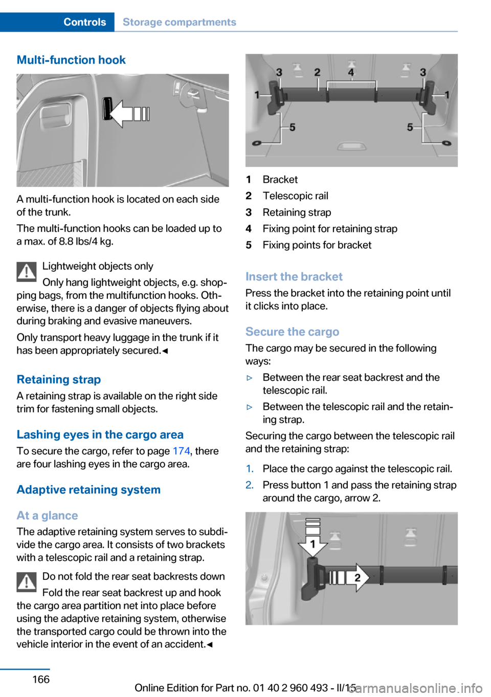
1Bracket2Telescopic rail3Retaining strap4Fixing point for retaining strap5Fixing points for bracket
Insert the bracket
Press the bracket into the retaining point until
it clicks into place.
Secure the cargo
The cargo may be secured in the following
ways:
▷Between the rear seat backrest and the
telescopic rail.▷Between the telescopic rail and the retain‐
ing strap.
Securing the cargo between the telescopic rail
and the retaining strap:
1.Place the cargo against the telescopic rail.2.Press button 1 and pass the retaining strap
around the cargo, arrow 2.Seite 166ControlsStorage compartments166
Online Edition for Part no. 01 40 2 960 493 - II/15