2016 Alfa Romeo Giulia wheel
[x] Cancel search: wheelPage 107 of 204

central tunnel fig. 101 switches on
together with the warning light
on the
instrument panel when the parking brake
is engaged and applied to the wheels.
Each automatic parking brake
engagement can be cancelled by pressing
the switch on the central tunnel and at
the same time moving the gear lever for
the transmission to position P (Park).
SAFE HOLD
It is a safety function that automatically
engages the electric parking brake in the
event of a dangerous condition for the
vehicle.
If:
the vehicle speed is below 2 mph
(3 km/h);
on vehicles with automatic
transmission, a transmission operating
mode different from P (Park) is activated;
the driver's seat belt is not fastened;
the driver side door is open;
no attempts to apply pressure on the
brake pedal have been detected.
the electric parking brake engages
automatically to prevent vehicle
movement.
The Safe Hold function can be
temporarily disabled by pressing the
switch located on the central tunnel and
the brake pedal at the same time, with
the vehicle stationary and the driver side
door open.Once disabled, the function will activate
again when the vehicle speed reaches
12 mph (20 km/h) or the ignition device is
moved to STOP and then to ON.
WARNING
103)In the case of parking manoeuvres on
roads on a gradient, the front wheels must
be steered towards the pavement (when
parking downhill), or in the opposite
direction if the vehicle is parked uphill. Block
the wheels with a wedge or a stone if the car
is parked on a steep slope.
104)Never leave children alone in an
unattended vehicle; make sure that when
you move away from the vehicle, you have
the key with you.
105)The electric parking brake must
always be engaged when leaving the vehicle.
MANUAL GEARBOX
106)
34)
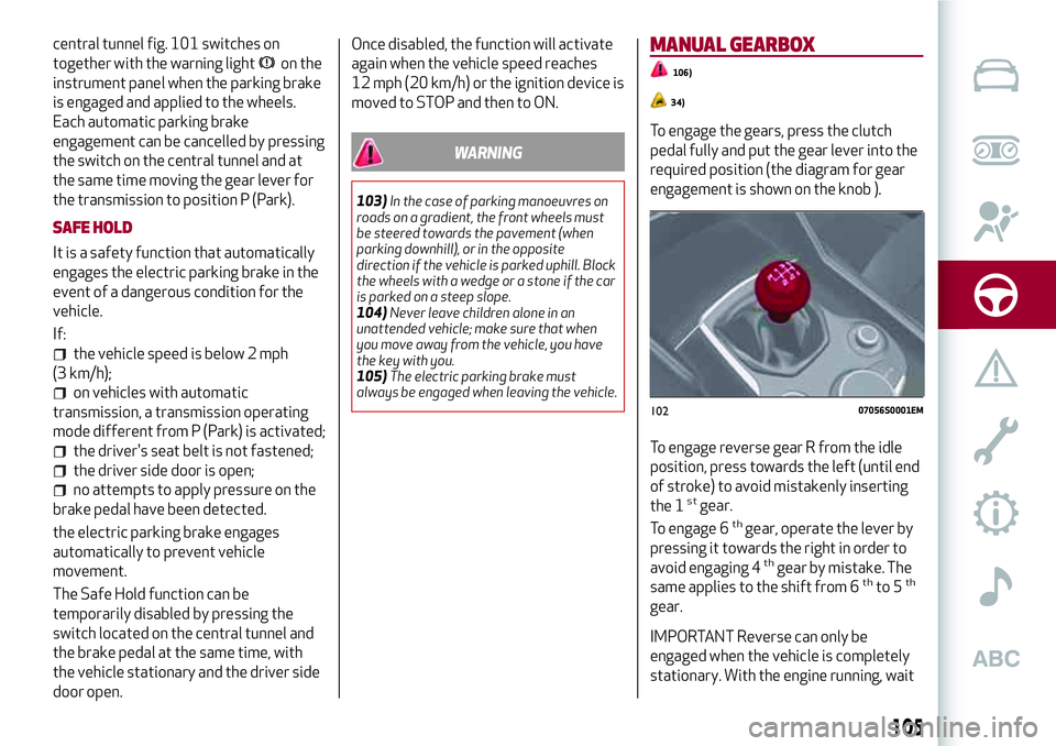
To engage the gears, press the clutch
pedal fully and put the gear lever into the
required position (the diagram for gear
engagement is shown on the knob ).
To engage reverse gear R from the idle
position, press towards the left (until end
of stroke) to avoid mistakenly inserting
the 1
stgear.
To engage 6thgear, operate the lever by
pressing it towards the right in order to
avoid engaging 4
thgear by mistake. The
same applies to the shift from 6thto 5th
gear.
IMPORTANT Reverse can only be
engaged when the vehicle is completely
stationary. With the engine running, wait
10207056S0001EM
105
Page 109 of 204

It is not possible to select N (Neutral)
mode from P (Park) mode.
P (Park) mode is automatically activated
if the following conditions are met
simultaneously:
D (Drive) or R (Reverse) mode is active;
the car’s speed is close to 0;
the brake pedal is released;
the driver’s seat belt is not fastened;
the driver’s door is open.
If using the gear shift in "sequential"
mode. you can activate it by moving the
lever from D (Drive) to the left and then
forward towards the - symbol or back
towards the + symbol and the gear is
shifted.
To exit position P (Park), or to pass from
position N (Neutral) to position D (Drive)
or R (Reverse) when the vehicle is
stopped or is moving at a low speed, the
brake pedal must also be pressed.
IMPORTANT DO NOT accelerate while
shifting from position P (or N) to another
position.
IMPORTANT After selecting a gear, wait
a few seconds before accelerating. This
precaution is particularly important with
a cold engine.
AutoStick - Manual (sequential)
shifting mode
In the case of frequent gearshifting (e.g.
for sport driving, when the vehicle is
driven with a heavy load, on slopes, with
strong headwind or when towing heavy
trailers), it is recommended to use the
Autostick (sequential shifting) mode to
select and keep a lower fixed ratio.
In this condition, using the lowest gear
improves the car performance,
preventing overheating.
It is possible to shift from position D
(Drive) to the sequential mode regardless
of vehicle speed.
Activation
Starting from D (Drive) mode, to activate
the sequential drive mode, move the
lever to the left (– and + indication of the
trim). The gear engaged will be shown on
the display.
Gearshifting is made by moving the gear
lever forwards, towards symbol – or
backwards, towards symbol +.Steering wheel stalks
(where provided)
The gear can be manually shifted also by
using the levers behind the steering
wheel, pull the right gear lever (+)
towards the steering wheel and release it
to engage a higher gear; perform the
same operation with the left lever (-) to
engage a lower gear fig. 105.
To engage N (Neutral): pull
simultaneously both levers.
To activate D (Drive) mode, from N
(Neutral), P (Parking) and R (Reverse):
push the brake pedal and the right lever
(+).
IMPORTANT When only one manual shift
is performed, the letter D will remain on
the display with the engaged gear next to
it.
10407076S0005EM
10507076S0006EM
107
Page 112 of 204

START & STOP EVO
The Start & Stop Evo system
automatically stops the engine each time
the vehicle is stationary and starts it
again when the driver wants to move off.
In this way, the vehicle efficiency is
increased, by reducing consumption,
dangerous gas emissions and sound
pollution.
OPERATING MODE
Stopping the engine
Versions with mechanical gearbox
With the vehicle stopped, the engine
stops with gearbox in neutral and clutch
pedal released.
Versions with automatic transmission
With vehicle at a standstill and brake
pedal pressed, the engine switches off if
the gear lever is in a position other than
R.
The system does not operate when the
gear lever is in R, for making parking
manoeuvres easier.
In the event of stops uphill, engine
switching off is disabled to make the "Hill
Start Assist" function available (works
only with running engine).
NOTE The engine can only be
automatically stopped after having run atabout 6 mph (10 km/h). After an
automatic restart, to stop the engine you
only need to move the vehicle (exceed a
speed of 0.3 mph (0.5 km/h)).
Engine stopping is signalled by the
symbol lighting up on the instrument
panel display.
Restarting the engine
Versions with mechanical gearbox
To restart the engine, press the clutch
pedal.
If the vehicle does not start when the
clutch is pressed, place the gear lever in
neutral and repeat the procedure. If the
problem persists, contact an Alfa Romeo
Dealership.
Versions with automatic transmission
To restart the engine, release the brake
pedal.
With brake pressed, if the gear lever is in
automatic mode - D (Drive) - the engine
can be restarted by moving the lever to R
(Reverse) or N (Neutral) or "AutoStick".
With brake pressed, if the gear lever is in
"AutoStick" mode, the engine can be
restarted by moving the lever to "+" or
"–", or R (Reverse) or N (Neutral).
When the engine has been stopped
automatically, keeping the brake pedal
pressed, the brake can be releasedkeeping the engine off by quickly shifting
the gear lever to P (Park).
To restart the engine, just move the lever
out of a position other than P.SYSTEM MANUAL ACTIVATION/
DEACTIVATION
110)
37)
To manually activate/deactivate the
system, press the button inserted in the
control panel on the left of the steering
wheel, fig. 107
LED off: system activated;
LED on: system deactivated.
10707126S0001EM
110
STARTING AND DRIVING
Page 119 of 204

46)Camera operation may also be
compromised by the presence of dust,
condensation, dirt or ice on the windscreen,
by traffic conditions (e.g. vehicles that are
driving not aligned with yours, vehicle driving
in a transverse or opposite way on the same
lane, bend with a small radius of curvature),
by road surface conditions and by driving
conditions (e.g. off-road driving). Make sure
the windscreen is always clean. Use specific
detergents and clean cloths to avoid
scratching the windscreen. The camera
operation may also be limited or absent in
some driving, traffic and road surface
conditions.REAR BACK-UP CAMERA /
DYNAMIC GRIDLINES
DESCRIPTION
The Rear Back-up Camera is located on
the boot, near the opening button,
fig. 114.
115)
47)
Camera activation/deactivation
The function can be activated/
deactivated on the Connect system.
Activating the device
To access the function, on the main menu
select the following items in sequence:
"Settings", "Driver assistance" and "Rear
Back-up Camera". The following
sub-menu appears:
Active
Switch-off delay;
Grille.
Select "Activate" to activate the camera
view on the Connect system display.
Every time reverse is engaged, the
display of the Connect system, fig. 115,
shows the area around the vehicle, as
seen by the Rear Back-up Camera.
SYMBOLS AND MESSAGES ON THE
DISPLAY
If activated, the grid is positioned on the
image to highlight the width of the
vehicle and the expected reversing path
in accordance with the steering wheel
position.
A superimposed central broken line
indicates the centre of the vehicle to
facilitate parking manoeuvres or tow
hook alignment. The various coloured
areas indicate the distance from the rear
of the vehicle.
11407186S0001EM11507186S0002EM
117
Page 127 of 204

REPLACING AN EXTERNAL BULB
IMPORTANT Only replace the bulb when
the engine is off. Also ensure that the
engine is cold, to prevent the risk of
burns.
Front light cluster with main
beam/dipped beam halogen headlights
Dipped headlights
To change the bulb of these lights,
proceed as follows:
remove the top cover from the wheel
arch by unscrewing the two fixing screws
fig. 119;
remove the cover fig. 120;
remove the bulb/connector assembly
from the headlight body fig. 121;
remove the bulb by sliding it off the
connector;
install the new bulb, making sure it is
correctly inserted in the connector;
then insert the bulb/connector
assembly in the housing on the headlight
body and make sure that it is locked
correctly;
remount the lid and cover, tightening
the fixing bolts.
Main beam headlights
To change the bulb of these lights,
proceed as follows:
operating inside the engine
compartment fig. 122;
remove the cover fig. 123;
turn the bulb, bulb holder and
connector assembly anticlockwise and
11908026S0001EM
12008026S0002EM
12108026S0003EM
12208026S0023EM
12308026S0004EM
125
Page 128 of 204

then slide it off the headlight body
fig. 124;
remove the bulb by sliding it off the
bulb holder;
install the new bulb, making sure it is
correctly inserted in the bulb holder;
then insert the bulb, bulb holder and
connector assembly in the housing on the
headlight body and turn it clockwise,
making sure that it is locked correctly;
refit the protective cover.
Direction indicators
To change the bulb of these lights,
proceed as follows:
operating inside the engine
compartment fig. 125;
remove cover by turning it fig. 126;
release the bulb, bulb holder and
connector assembly and then slide it off
the headlight body fig. 127;
remove the bulb by sliding it off the
bulb holder;
install the new bulb, making sure it is
correctly inserted in the bulb holder;
then insert the bulb, bulb holder and
connector assembly in the housing on the
headlight body and turn it clockwise,
making sure that it is locked correctly;
refit the protective cover.
Front fog lights
To replace the bulbs, proceed as follows:
remove the lower cover from the
wheel arch by unscrewing the two fixing
screws fig. 128;
12408026S0005EM
12508026S0023EM
12608026S0006EM
12708026S0007EM
126
IN AN EMERGENCY
Page 136 of 204

131)Repairs are not possible in the case of
damage to the wheel rim (bad groove
distortion causing air loss). Do not remove
foreign bodies (screws or nails) from the
tyre.
132)Never operate the compressor for
longer than 20 consecutive minutes. Risk of
overheating. The Tire Repair Kit is not
suitable for definitive repairs, so the
repaired tyres may only be used temporarily.
133)As required by current regulations, the
information on chemical substances for the
protection of human health and the
environment and on the safe use of the
sealing fluid are on the packaging label.
Compliance with the indications on the label
is an essential condition to ensure the safety
and the effectiveness of the product.
Remember to carefully read the label before
use; the user of the product is responsible
for any damages caused by improper use.
The sealing fluid has an expiry date. Replace
the bottle if the sealant has expired.
134)If the pressure falls below 1.8 bar, do
not drive any further: the Tire Repair Kit
cannot guarantee proper seal because the
tyre is too damaged. Contact an Alfa Romeo
Dealership.
135)The Tire Repair Kit provide a
temporary repair, therefore the tyre must be
examined and repaired by a specialist as
soon as possible. The sealant is suitable for
use at temperatures in the range from −40°C
to +50°C.IMPORTANT
52)In the event of a puncture caused by
foreign bodies, the kit may be used to repair
tyres showing damage on the tyre tread up
to max. 6mm diameter.
IMPORTANT
3)Dispose of the bottle and the sealant
liquid properly. Have them disposed of in
compliance with national and local
regulations.
EMERGENCY STARTING
If the battery is flat, a jump starting can
be performed using the battery and the
cables of another vehicle, or using an
auxiliary battery. In all cases, the battery
used must have a capacity equal to or a
little higher than the flat one.
Jump starting may be dangerous if
carried out incorrectly: carefully follow
the procedures described below.
53)
IMPORTANT NOTES
Do not use an auxiliary battery or any
other source of external supply with a
voltage above 12 V: the battery, the
starter, the alternator and the electrical
system of the vehicle could be damaged.
Do not attempt jump starting if the
battery is frozen. The battery could break
and explode!
REMOTE BATTERY CONNECTION
POLES
To facilitate the operation, the remote
poles of the battery for the jump starting
can be found in the engine compartment:
the battery, on the other hand, is placed
in the luggage compartment.
The negative terminal (-) fig. 141 fig. 8 is
positioned next to the right bonnet lock.
134
IN AN EMERGENCY
Page 140 of 204

BROKEN-DOWN VEHICLE
TOWING
REAR WHEEL DRIVE (RWD) VERSIONS
It is recommended to tow the vehicle
with all four wheels lifted from the
ground on the platform of a roadside
assistance vehicle.
If a breakdown truck with platform is not
available, the vehicle must be towed with
the rear wheels LIFTED from the ground
(using a trailer or special equipment
allowing lifting of the rear wheels).
IMPORTANT Towing vehicles without
complying with the above mentioned
prescriptions can cause serious damage
to the vehicle.FOUR-WHEEL DRIVE (AWD) VERSIONS
It is recommended to tow the vehicle
with all four wheels lifted from the
ground on the platform of a roadside
assistance vehicle.
IMPORTANT Avoid lifting the front (or
rear) wheels only, using a trailer or
vehicle that allows lifting the wheels of
one axle only. Lifting the front (or rear)
wheels only while towing might damage
the transmission or the transfer unit.
IMPORTANT If a vehicle is towed without
complying with the above requirements,
the transmission and/or the transfer unit
might be seriously damaged. Damage due
to incorrect towing is not covered by
warranty.
TOWING THE VEHICLE
140) 141)
In order to be able to tow the vehicle,
which has been in an accident or has
broken down, on the road surface and
only for short distances, a tow hook is
provided in the tools container inside the
boot.
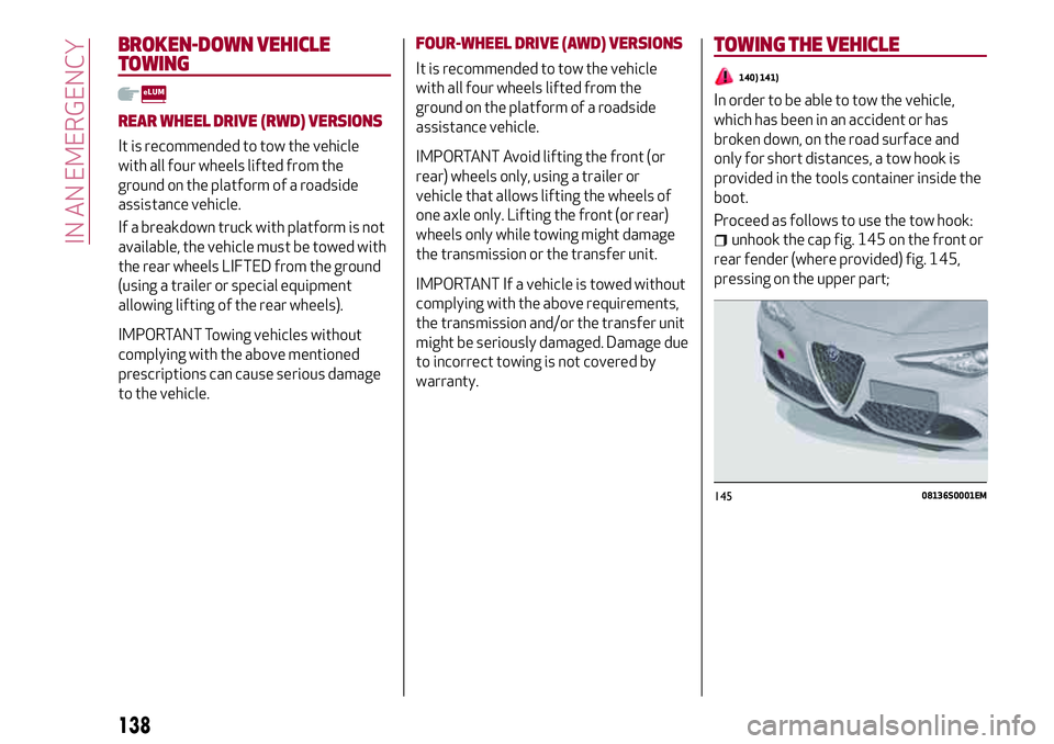
Proceed as follows to use the tow hook:
unhook the cap fig. 145 on the front or
rear fender (where provided) fig. 145,
pressing on the upper part;
14508136S0001EM
138
IN AN EMERGENCY