Page 65 of 126
INSTRUMENT AND CONTROL FUNCTIONS
4-46
1
2
345
6
7
8
9
10
11
12
EAU44893
Ignition circuit cut-off systemThe ignition circuit cut-off system (com-
prising the sidestand switch, clutch
switch and neutral switch) has the fol-
lowing functions.
It prevents starting when the trans-
mission is in gear and the sides-
tand is up, but the clutch lever is
not pulled.
It prevents starting when the trans-
mission is in gear and the clutch le-
ver is pulled, but the sidestand is
still down.
It cuts the running engine when the
transmission is in gear and the sid-
estand is moved down.
Periodically check the operation of the
ignition circuit cut-of f system according
to the following procedure.
2CR-9-E0_1.book 46 ページ 2015年1月5日 月曜日 午前11時54分
Page 66 of 126

INSTRUMENT AND CONTROL FUNCTIONS
4-47
1
2
34
5
6
7
8
9
10
11
12
With the engine turned off:
1. Move the sidestand down.
2. Make sure that the engine stop switch is set to “
3. Turn the key on.
4. Shift the transmission into the neutral position.
5. Push the start switch.
Does the engine start?
With the engine still running:
6. Move the sidestand up.
7. Keep the clutch lever pulled.
8. Shift the transmission into gear.
9. Move the sidestand down.
Does the engine stall?
After the engine has stalled:
10. Move the sidestand up.
11. Keep the clutch lever pulled.
12. Push the start switch.
Does the engine start?
The system is OK. The motorcycle can be ridden. The neutral switch may not be working correctly.
The motorcycle should not be ridden until
checked by a Yamaha dealer.
The sidestand switch may not be working correctly.
The motorcycle should not be ridden until
checked by a Yamaha dealer.
The clutch switch may not be working correctly.
The motorcycle should not be ridden until
checked by a Yamaha dealer.
YES NO YES NO YES NO
If a malfunction is noted, have a Yamaha
dealer check the system before riding.
WARNING
”.
2CR-9-E0_1.book 47 ページ 2015年1月5日 月曜日 午前11時54分
Page 67 of 126
INSTRUMENT AND CONTROL FUNCTIONS
4-48
1
2
345
6
7
8
9
10
11
12
EAU59950
Auxiliary DC connector
WARNING
EWA12532
To prevent electrical shock or
short-circuiting, make sure that the
cap is installed when the auxiliaryDC connector is not being used.NOTICE
ECA20090
The accessory connected to the
auxiliary DC connector should not
be used with the engine turned off,
and the load must never exceed 24
W (2 A), otherwise the fuse may blowor the battery may discharge. This vehicle is equipped with an auxilia-
ry DC connector. A 12–V accessory
connected to the auxiliary DC connec-
tor can be used when the key is in the
“ON” position.1. Auxiliary DC connector
2. Auxiliary DC connector cap21
2CR-9-E0_1.book 48 ページ 2015年1月5日 月曜日 午前11時54分
Page 68 of 126

5-1
1
2
3
45
6
7
8
9
10
11
12
FOR YOUR SAFETY – PRE-OPERATION CHECKS
EAU15599
Inspect your vehicle each time you use it to make sure the vehi cle is in safe operating condition. Always follow the inspection
and maintenance procedures and schedules described in the Owner’s Manual.
WARNING
EWA11152
Failure to inspect or maintain the vehicle properly increases the possibility of an accident or equipment damage.
Do not operate the vehicle if you find any problem. If a problem cannot be corrected by the procedures provided inthis manual, have the vehicle inspected by a Yamaha dealer.
Before using this vehicle, check the following points:
ITEM CHECKS PAGE
Fuel Check fuel level in fuel tank.
Refuel if necessary.
Check fuel line for leakage.
Check fuel tank breather hose and overflow hose for obstructions, cracks or
damage, and check hose connections. 4-33, 4-35
Engine oil Check oil level in engine.
If necessary, add recommended oil to specified level.
Check vehicle for oil leakage. 7-12
Coolant Check coolant level in reservoir.
If necessary, add recommended coolant to specified level.
Check cooling system for leakage. 7-14
Front brake Check operation.
If soft or spongy, have Yamaha dealer bleed hydraulic system.
Check brake pads for wear.
Replace if necessary.
Check fluid level in reservoir.
If necessary, add specified brake fluid to specified level.
Check hydraulic system for leakage. 7-23, 7-24
2CR-9-E0_1.book 1 ページ 2015年1月5日 月曜日 午前11時54分
Page 69 of 126

FOR YOUR SAFETY – PRE-OPERATION CHECKS
5-2
1
2
3
456
7
8
9
10
11
12
Rear brake Check operation.
If soft or spongy, have Yamaha dealer bleed hydraulic system.
Check brake pads for wear.
Replace if necessary.
Check fluid level in reservoir.
If necessary, add specified brake fluid to specified level.
Check hydraulic system for leakage. 7-23, 7-24
Clutch Check operation.
Lubricate cable if necessary.
Check lever free play.
Adjust if necessary. 7-22
Throttle grip Make sure that operation is smooth.
Check throttle grip free play.
If necessary, have Yamaha dealer adjust th
rottle grip free play and lubricate cable
and grip housing. 7-18, 7-28
Control cables Make sure that operation is smooth.
Lubricate if necessary. 7-27
Drive chain Check chain slack.
Adjust if necessary.
Check chain condition.
Lubricate if necessary. 7-25, 7-27
Wheels and tires Check for damage.
Check tire condition and tread depth.
Check air pressure.
Correct if necessary. 7-18, 7-21
Brake and shift pedals Make sure that operation is smooth.
Lubricate pedal pivoting points if necessary. 7-28
Brake and clutch levers Make sure that operation is smooth.
Lubricate lever pivoting points if necessary. 7-29
Sidestand Make sure that operation is smooth.
Lubricate pivot if necessary. 7-29
Chassis fasteners Make sure that all nuts, bolts and screws are properly tightened.
Tighten if necessary. —
ITEM CHECKS PAGE
2CR-9-E0_1.book 2 ページ 2015年1月5日 月曜日 午前11時54分
Page 70 of 126
FOR YOUR SAFETY – PRE-OPERATION CHECKS
5-3
1
2
3
45
6
7
8
9
10
11
12
Air intake duct Make sure that the air intake duct is not blocked.
Remove any foreign objects from the screen if necessary. —
Instruments, lights, signals
and switches Check operation.
Correct if necessary.
—
Sidestand switch Check operation of ignition circuit cut-off system.
If system is not working correctly, have Yamaha dealer check vehicle. 4-45
ITEM CHECKS PAGE
2CR-9-E0_1.book 3 ページ 2015年1月5日 月曜日 午前11時54分
Page 71 of 126

6-1
1
2
3
4
567
8
9
10
11
12
OPERATION AND IMPORT ANT RIDING POINTS
EAU15952
Read the Owner’s Manual carefully to
become familiar with all controls. If
there is a control or function you do not
understand, ask your Yamaha dealer.
WARNING
EWA10272
Failure to familiarize yourself with
the controls can lead to loss of con-
trol, which could cause an accidentor injury.
EAU68220
TIPThis model is equipped with:
an inertial measurement unit (IMU)
that will stop the engine in case of
a turnover. In this case, the display
will indicate error code 30, but this
is not a malfunction. Turn the key
to “OFF” and then to “ON” to clear
the error code. Failing to do so will
prevent the engine from starting
even though the engine will crank
when pushing the start switch.
an engine auto-stop system. The
engine stops automatically if left
idling for 20 minutes. If the engine
stops, simply push the start switchto restart the engine.
EAU67071
Starting the engineIn order for the ignition circuit cut-off
system to enable starting, one of the
following conditions must be met:
The transmission is in the neutral
position.
The transmission is in gear with
the clutch lever pulled and the sid-
estand up.
See page 4-46 for more informa-
tion.
1. Turn the key to “ON” and make sure that the engine stop switch is
set to “ ”.
The following warning lights and
indicator lights should come on for
a few seconds, then go off.
Fuel level warning light
Shift timing indicator light
Engine trouble and system
warning light
Stability control indicator light
Immobilizer system indicator
light
The ABS warning light should
come on when the key is turned to
“ON” and then go off after the vehi-
cle reaches a traveling speed of 10
2CR-9-E0_1.book 1 ページ 2015年1月5日 月曜日 午前11時54分
Page 72 of 126
.
The oil pressure and coolant tem-
perature warning light should
come on again after going off brief-
ly, and then rem")
OPERATION AND IMPORTANT RIDING POINTS
6-2
1
2
3
4
56
7
8
9
10
11
12 km/h (6 mi/h).
The oil pressure and coolant tem-
perature warning light should
come on again after going off brief-
ly, and then remain on until the en-
gine is started.
NOTICE
ECA22510
If a warning or indicator light does
not work as described above, see
page 4-6 for the corresponding
warning and indicator light circuitcheck.
2. Shift the transmission into the neu- tral position. The neutral indicator
light should come on. If not, ask a
Yamaha dealer to check the elec-
trical circuit.
3. Start the engine by pushing the start switch.
If the engine does not start within 5
seconds of pressing the start
switch, wait 10 seconds before
pressing the switch again to allow
the battery voltage to restore.NOTICE
ECA11043
For maximum engine life, never ac- celerate hard when the engine is
cold!
EAU67080
ShiftingShifting gears lets you control the
amount of engine power available for
starting off, accelerating, climbing hills,
etc.
The gear positions are shown in the il-
lustration.TIPFor speedy upshifts, turn on the quick
shift system. See QSS on page 4-17 formore information.NOTICE
ECA22520
Even with the transmission in
1. Shift pedal
2. Neutral position
1
1
2
2 3 4
5 6
N
2CR-9-E0_1.book 2 ページ 2015年1月5日 月曜日 午前11時54分
 1
1 2
2 3
3 4
4 5
5 6
6 7
7 8
8 9
9 10
10 11
11 12
12 13
13 14
14 15
15 16
16 17
17 18
18 19
19 20
20 21
21 22
22 23
23 24
24 25
25 26
26 27
27 28
28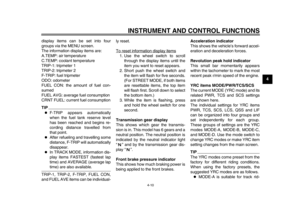 29
29 30
30 31
31 32
32 33
33 34
34 35
35 36
36 37
37 38
38 39
39 40
40 41
41 42
42 43
43 44
44 45
45 46
46 47
47 48
48 49
49 50
50 51
51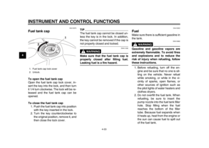 52
52 53
53 54
54 55
55 56
56 57
57 58
58 59
59 60
60 61
61 62
62 63
63 64
64 65
65 66
66 67
67 68
68 69
69 70
70 71
71 72
72 73
73 74
74 75
75 76
76 77
77 78
78 79
79 80
80 81
81 82
82 83
83 84
84 85
85 86
86 87
87 88
88 89
89 90
90 91
91 92
92 93
93 94
94 95
95 96
96 97
97 98
98 99
99 100
100 101
101 102
102 103
103 104
104 105
105 106
106 107
107 108
108 109
109 110
110 111
111 112
112 113
113 114
114 115
115 116
116 117
117 118
118 119
119 120
120 121
121 122
122 123
123 124
124 125
125

