2015 YAMAHA WOLVERINE lock
[x] Cancel search: lockPage 6 of 186

EBU31120
CONTENTS
LOCATION OF THE WARNING AND
SPECIFICATION LABELS ....................... 1-1
SAFETY INFORMATION ......................... 2-1
DESCRIPTION......................................... 3-1Left view ............................................... 3-1
Right view ............................................. 3-2
Controls and instruments ..................... 3-3
INSTRUMENT AND CONTROL
FUNCTIONS............................................ 4-1 Main switch .......................................... 4-1
Indicator lights and warning lights ....... 4-2
Multi-function meter unit ...................... 4-6
Light switch ........................................ 4-10
On-Command drive knob “2WD/4WD/DIFF LOCK” .................. 4-11
Horn switch ........................................ 4-12
Accelerator pedal ............................... 4-12
Brake pedal ........................................ 4-12 Parking brake lever ............................ 4-13
Drive select lever ................................ 4-13
Fuel tank cap...................................... 4-14
Doors .................................................. 4-14
Seats .................................................. 4-15
Adjusting the driver seat position....... 4-16
Seat belts ........................................... 4-17
Glove compartment ........................... 4-17
Storage compartments ...................... 4-18
Cup holders ........................................ 4-19
Cargo bed .......................................... 4-20
Adjusting the front shock absorber
assemblies ....................................... 4-22
Adjusting the rear shock absorber
assemblies ....................................... 4-27
Trailer hitch bracket and receiver....... 4-32
Auxiliary DC jack ................................ 4-32
FOR YOUR SAFETY –
PRE-OPERATION CHECKS.................... 5-1 Front and rear brakes ........................... 5-3
Fuel....................................................... 5-3
Engine oil.............................................. 5-5U2MB7AE0.book Page 1 Thursday, January 29, 2015 3:42 PM
Page 21 of 186

1-13
1
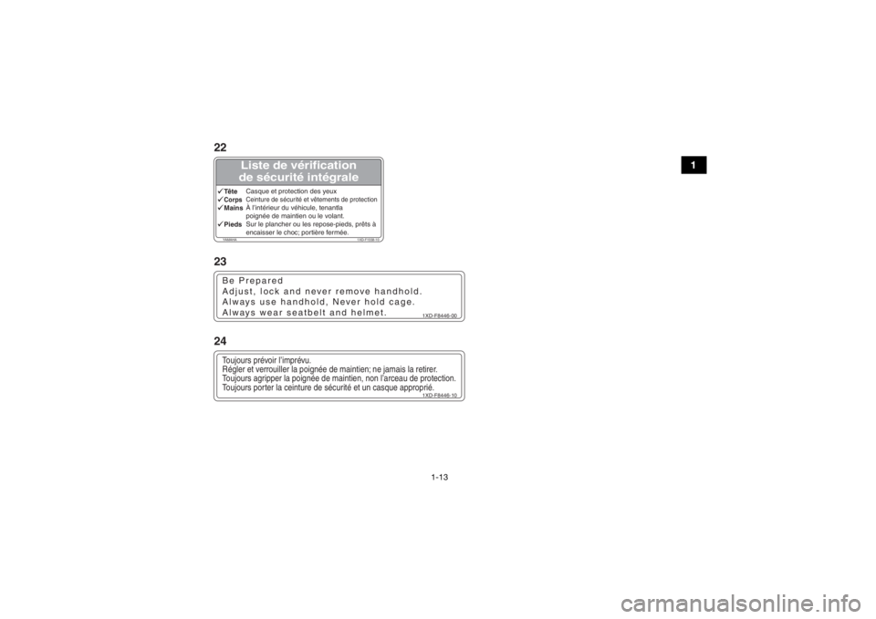
Liste de vérification
de sécurité intégrale
YAMAHA 1XD-F1558-10TêteCasque et protection des yeuxCorps Ceinture de sécurité et vêtements de protectionMainsÀ l’intérieur du véhicule, tenantla
poignée de maintien ou le volant.PiedsSur le plancher ou les repose-pieds, prêts à
encaisser le choc; portière fermée.
1XD-F8446-00
Be Prepared
Adjust, lock and never remove handhold.
Always use handhold, Never hold cage.
Always wear seatbelt and helmet.
1XD-F8446-10
Toujours prévoir l’imprévu.
Régler et verrouiller la poignée de maintien; ne jamais la retirer.
Toujours agripper la poignée de maintien, non l’arceau de protection.
Toujours porter la ceinture de sécurité et un casque approprié.22
23
24
U2MB7AE0.book Page 13 Thursday, January 29, 2015 3:42 PM
Page 28 of 186

1-20
1
Head to Toe
Safety Checklist
YAMAHA 1XD-F1558-00HeadHelmet and eye protection.BodySeatbelt and protective clothing.HandsInside vehicle and holding the
handhold or steering wheel.FeetOn floor or footrests,
ready to brace, and door closed.
1XD-F8446-00
Be Prepared
Adjust, lock and never remove handhold.
Always use handhold, Never hold cage.
Always wear seatbelt and helmet.YAMAHA
2MB-F1568-00
WARNING
DRIVER DRIVER
UNDER
UNDER16
16DRIVERUNDER16
Improper Use of Off-Highway Vehicle Can Cause Severe Injury or Death
Read Owner’s Manual
Read Tips Guide for the Recreational Off-Highway Vehicle Driver Follow All Instruction and Warnings
Be Prepared
Drive Responsibly
If you think or feel the vehicle may tip or roll,
reduce your risk to injury: Pay Attention and Plan Ahead
Do not allow careless or reckless driving.
Do your part to prevent injuries: Require Proper Use of Your Vehicle
Rollovers have caused
severe injuries and death,
even on flat, open areas.
Stay completely inside the vehicle.
Passenger must be able to reach the handhold while
keeping feet flat on floor and sitting upright with
back against seat.
Driver must be able to comfortably reach all controls
while sitting upright with back against seat.
Wear an approved helmet, eye protection and protective gear.
Fasten seat belts.
Do not allow anyone to ride in the cargo bed.
Avoid side hilling (riding across slopes).
Plan for hills, rough terrain, ruts, and other changes
in traction and terrain. Avoid paved surfaces.
Avoid hard acceleration when turning, even from a stop.
Slow down before entering a turn.
Avoid abrupt maneuvers, sideways sliding, skidding,
or fishtailing, and never do donuts.
Avoid loss of control and rollovers: Do not put any part of your body outside of
the vehicle for any reason.
Keep a firm grip on the steering wheel
or handhold and brace yourself.
Do not exceed seating capacity: 1 passenger.
Do not allow operation on public roads
(unless designated for off-highway vehicle access)
— collisions with cars and trucks can occur.
Do not let people drive or ride
after using alcohol or drugs.
Make sure operators are 16 or older
with valid driver’s license.
10
11
12
U2MB7AE0.book Page 20 Thursday, January 29, 2015 3:42 PM
Page 40 of 186

4-2
4
EBU31260Indicator lights and warning lights
EBU31270Low-range indicator light “L”
This indicator light comes on when the drive
select lever is in the “L” position.EBU31280High-range indicator light “H”
This indicator light comes on when the drive
select lever is in the “H” position.
1. On-Command differential gear lock indicator light “DIFF. LOCK”
2. Low-range indicator light “L”
3. High-range indicator light “H”
4. Neutral indicator light “N”
5. Reverse indicator light “R”
6. Parking brake indicator light “ ”
7. On-Command four-wheel-drive/differential gear lock indicator “ ”/“ ”
8. Engine trouble warning light “ ”
9. Coolant temperature warning light “ ”
10.Electric Power Steering warning light “EPS” (for EPS model)356421
7
8109
1. Helmet indicator light “ ”
2. Seat belt indicator light “ ”
21
U2MB7AE0.book Page 2 Thursday, January 29, 2015 3:42 PM
Page 41 of 186

4-3
4
EBU31290Neutral indicator light “N”
This indicator light comes on when the drive
select lever is in the “N” position.EBU31300Reverse indicator light “R”
This indicator light comes on when the drive
select lever is in the “R” position.EBU31310Parking brake indicator light “ ”
This indicator light comes on when the park-
ing brake is applied.EBU31320On-Command four-wheel-drive
indicator “ ”, On-Command differential
gear lock indicator “ ” and indicator light
“DIFF. LOCK”
The On-Command four-wheel-drive
indicator “ ” comes on when the On-Com-
mand drive knob “2WD/4WD/DIFF LOCK” is
set to the “4WD” position.The On-Command differential gear lock
indicator “ ” and the On-Command differen-
tial gear lock indicator light “DIFF. LOCK”
come on when the On-Command drive knob
“2WD/4WD/DIFF LOCK” is set to the “DIFF
LOCK” position.
TIP
Due to the synchronizing mechanism in the
differential gear case, the four-wheel-drive
indicator may not come on until the vehicle
starts moving.
When the On-Command drive knob
“2WD/4WD/DIFF LOCK” is set to “DIFF
LOCK” or “4WD”, the indicator “ ” and the
indicator light “DIFF. LOCK” will flash until
the differential gear is completely locked or
unlocked. If the indicator and the indicator
light continue to flash, the differential is not
completely locked or unlocked. In this
case, start moving to allow time for the dif-
ferential to lock or unlock.
U2MB7AE0.book Page 3 Thursday, January 29, 2015 3:42 PM
Page 44 of 186

4-6
4
EBU31380Multi-function meter unitThe multi-function meter unit is equipped with
the following:
a speedometer
an odometer
two tripmeters (which show the distance
traveled since they were last set to zero)
a clock
an hour meter (which shows the total time
the engine has been running)
a voltage display (which shows the battery
voltage)
a fuel meter
a self-diagnosis device
Odometer and tripmeter modes1. “CLOCK” button
2. “RESET” button
3. “SELECT” button
4. Speedometer
5. Fuel meter
6. Clock/Hour meter/Voltage display
7. Odometer/Tripmeter A/Tripmeter B321
4
5
6
7
1. “SELECT” button
2. “RESET” button
3. Odometer/Tripmeter A/Tripmeter B12
3
U2MB7AE0.book Page 6 Thursday, January 29, 2015 3:42 PM
Page 45 of 186

4-7
4
Pushing the “SELECT” button switches the
display between the odometer mode “ODO”
and the tripmeter modes “TRIP A” and “TRIP
B” in the following order:
ODO → TRIP A → TRIP B → ODO
To reset a tripmeter, select it by pushing the
“SELECT” button, and then push the “RE-
SET” button for at least three seconds. The
tripmeters can be used to estimate the dis-
tance that can be traveled with a full tank of
fuel. This information enables you to plan fu-
ture fuel stops.TIPTo switch the display between “mph” and
“km/h”, turn the key to “ ” (off), then push
and hold the “SELECT” button while turning
the key to “ ” (on).
Clock, hour meter and voltage display
modes
Pushing the “CLOCK” button switches the
display between the clock mode “CLOCK”,
the hour meter mode “HOUR”, and the volt-
age display mode “ ” in the following or-
der:
CLOCK → HOUR → → CLOCK1. “SELECT” button
2. “RESET” button
3. “CLOCK” button
4. Clock/Hour meter/Voltage display
4
123
U2MB7AE0.book Page 7 Thursday, January 29, 2015 3:42 PM
Page 46 of 186

4-8
4
To set the clock1. Set the display to the clock mode.
2. Push the “SELECT” button and “RESET”button together for at least three sec-
onds.
3. When the hour digits start flashing, push the “RESET” button to set the hours.
4. Push the “SELECT” button, and the min-
ute digits will start flashing.
5. Push the “RESET” button to set the min- utes.
6. Push the “SELECT” button, and then re- lease it to start the clock. Voltage display mode
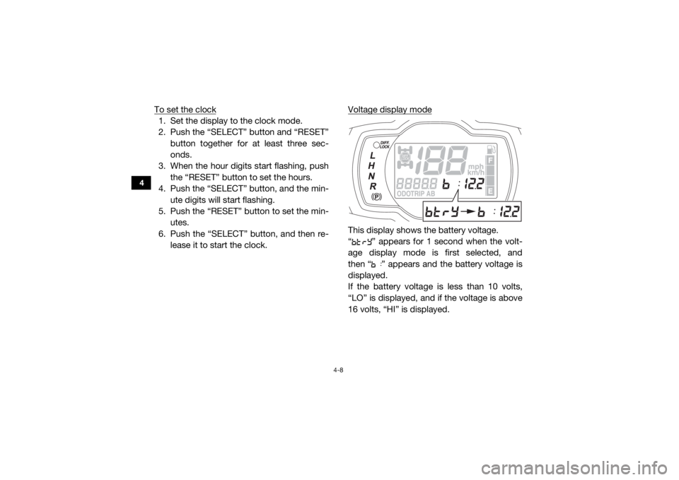
This display shows the battery voltage.
“ ” appears for 1 second when the volt-
age display mode is first selected, and
then “ ” appears and the battery voltage is
displayed.
If the battery voltage is less than 10 volts,
“LO” is displayed, and if the voltage is above
16 volts, “HI” is displayed.
U2MB7AE0.book Page 8 Thursday, January 29, 2015 3:42 PM