Page 65 of 118
Operation and handling requirements
59
(5) Loosen the fuel filler cap and remove it.
(6) Slowly add fuel to the fuel tank.
(7) Stop filling when the fuel level reachesapproximately 50 mm (2 in) from the top
of the fuel tank. Do not overfill the fuel
tank. Because fuel expands when it
heats up, heat from the engine or the sun
can cause fuel to spill out of the fuel tank. Do not leave the watercraft with a full
tank in direct sunlight.
(8) Wipe up any spilled fuel immediately with a dry cloth.
(9) Securely install the fuel filler cap by tight- ening it until it clicks.
(10) Push the rear of the hood down to se- curely lock it in place. Make sure that the
1Fuel filler cap
Fuel tank capacity:
70 L (18.5 US gal, 15.4 Imp.gal)
1
1Top of the fuel tank
2 Approximately 50 mm (2 in) from top of the
fuel tank
1 Top of the fuel tank
2 Approximately 50 mm (2 in) from top of the
fuel tank
1
2
21
UF2T74E0.book Page 59 Wednesday, July 2, 2014 11:17 AM
Page 66 of 118
 Securely install the seats in their original positions.EJU40291
Engine oil req")
Operation and handling requirements
60
fuel filler cap and the hood are securely
closed before using the watercraft.
(11) Securely install the seats in their original positions.EJU40291
Engine oil requirementsEJU41513Engine oil
NOTICE
ECJ00282
Use only 4-stroke engine oil. Usage of 2-
stroke engine oil could result in severe en-
gine damage.
TIP:
When the engine is operated at high speeds,
some engine oil may be consumed. Be sure
to check the engine oil level.
Checking the engine oil level
WARNING
EWJ00341
Engine oil is extremely hot immediately af-
ter the engine is turned off. Coming in con-
tact with or getting any engine oil on your
clothes could result in burns.
NOTICE
ECJ01002
Make sure that debris and water do not
enter the oil filler hole. Debris and water in
the engine oil can cause serious engine
damage.
To check the engine oil level:
(1) Place the watercraft in a precisely levelposition on land with the engine
stopped. If the engine was running, allow
the engine oil to settle by waiting 5 minu-
tes or more before checking the oil level.
(2) Remove the seats. (See page 49 for seat removal and installation procedures.)
Recommended engine oil type:SAE 10W-30, 10W-40, 20W-40,
20W-50
Recommended engine oil grade: API SE,SF,SG,SH,SJ,SL
UF2T74E0.book Page 60 Wednesday, July 2, 2014 11:17 AM
Page 67 of 118
 Remove the dipstick and wipe it clean.
(4) Insert the dipstick back into the dipsticktube completely. Remove the dipstick
again and make sure that the engine")
Operation and handling requirements
61
(3) Remove the dipstick and wipe it clean.
(4) Insert the dipstick back into the dipsticktube completely. Remove the dipstick
again and make sure that the engine oil
level is between the minimum and maxi-
mum level marks.
(5) If the engine oil level is significantly above the maximum level mark, consult
a Yamaha dealer. If the engine oil level is
below the minimum level mark, add en-
gine oil. (6) Loosen the engine oil filler cap and re-
move it.
(7) Slowly add engine oil.
TIP:
The difference between the minimum and
maximum level marks on the dipstick is equal
to approximately 1 L (1.06 US qt, 0.88 Imp.qt)
of engine oil.
(8) Wait approximately 5 minutes to allow the engine oil to settle, and then check
the engine oil level again.
(9) Repeat steps 3–8 until the engine oil is at the proper level.
(10) Securely install the engine oil filler cap by tightening it until it stops.
(11) Securely install the seats in their original positions.
1Dipstick
1 Maximum level mark
2 Minimum level mark
1
1
2
1Engine oil filler cap
1
UF2T74E0.book Page 61 Wednesday, July 2, 2014 11:17 AM
Page 68 of 118

Operation and handling requirements
62
EJU40022
Draining the bilge water
NOTICE
ECJ01302
Do not run the engine at full throttle when
bilge water remains in the engine com-
partment. The bilge water can splash into
the engine, which can result in severe
damage.
EJU40035Draining the bilge water on land
To drain the bilge water on land:
(1) Loosen the stern drain plugs and removethem.
(2) Raise the bow of the watercraft, such as by placing the watercraft on a slope, to
drain the bilge water from the engine
compartment.
(3) After the bilge water has drained from the stern drain plug holes, wipe up any re- maining moisture in the engine compart-
ment with a dry cloth.
(4) Securely install the stern drain plugs by tightening them until they stop. NOTICE:
Before installing the stern drain plugs,
clean the drain plug threads and the
O-rings on the plugs to remove any
foreign materials, such as dirt or sand.
Otherwise, the stern drain plugs could
be damaged, allowing water to enter
the engine compartment. Check the
O-rings on the stern drain plugs and
make sure that the plugs are tightened
securely before launching the water-
craft. Otherwise, water may flood the
engine compartment and cause the
watercraft to submerge.
[ECJ00363]
EJU42171
Draining the bilge water on water
A small quantity of bilge water will remain in
the engine compartment even after the bilge
water is drained on water. To completely
drain the bilge water, remove the watercraft
from the water and drain the bilge water on
land.
Jet vacuum bilge draining system
While the watercraft is operating, bilge water
in the engine compartment is drawn in by the
vacuum that is generated in the jet pump and
discharged from the watercraft through the
jet thrust nozzle.
To drain the bilge water on water:
Operate the watercraft as straight as possible
and above planing speed for at least 2 minu-
tes. NOTICE: Do not run the engine at full
throttle for at least 1 minute after the en-
gine has been restarted. Bilge water in the
engine compartment can splash into the
1 Stern drain plug
1
UF2T74E0.book Page 62 Wednesday, July 2, 2014 11:17 AM
Page 69 of 118
Operation and handling requirements
63
engine, which can result in severe dam-
age.
[ECJ00554]
Electric bilge draining system
Bilge water in the engine compartment is
drawn in by the operation of the electric bilge
pump and discharged from the watercraft.
To drain the bilge water:
Start the engine to operate the electric bilge
pump.
TIP:
The electric bilge pump continues to operate
for a short time after the engine stops.
EJU42432
Transporting on a trailer
When transporting the watercraft on a trailer,
secure the tie downs to the trailer through the
bow eye and stern eyes. NOTICE: Do not at-
tach ropes or tie downs to any part of the
watercraft other than the bow eye and
stern eyes to secure the watercraft to the
trailer. Otherwise, the watercraft may be
damaged. Wrap the ropes or tie downs
with towels or rags where they touch the
body of the watercraft to avoid scratches
or damage.
[ECJ02150]
UF2T74E0.book Page 63 Wednesday, July 2, 2014 11:17 AM
Page 70 of 118
First-time operation
64
EJU36666
Engine break-in
NOTICE
ECJ00432
Failure to perform the engine break-in
could result in reduced engine life or even
severe engine damage.
The engine break-in is essential to allow the
various components of the engine to wear
and polish themselves to the correct operat-
ing clearances. This ensures proper perfor-
mance and promotes longer component life.
To perform the engine break-in:
(1) Check the engine oil level. (See page 60for information on checking the engine
oil level.)
(2) Launch the watercraft and start the en- gine. (See page 77 for information on
starting the engine.)
(3) For the first 5 minutes, operate with the engine speed at 2000 r/min.
(4) For the next 30 minutes, operate with the engine speed below 5000 r/min.
(5) For the next 1 hour, operate with the en- gine speed below 6000 r/min.
After the engine break-in is complete, the wa-
tercraft can be operated normally.
UF2T74E0.book Page 64 Wednesday, July 2, 2014 11:17 AM
Page 71 of 118

Pre-operation checks
65
EJU31982
WARNING
EWJ00412
Failure to inspect or maintain the watercraft properly increases the possibility of an ac-
cident or damage to the watercraft. Do not operate the watercraft if you find any prob-
lem. If a problem cannot be corrected by the procedures provided in this manual, have
the watercraft inspected by a Yamaha dealer.
EJU41234Pre-operation checklist
Before using this watercraft, be sure to perform the checks in the following checklist.
ITEMROUTINEPAGE
PRE-LAUNCH CHECKS
Engine compartment Ventilate the engine compartment.
Check inside the engine compartment for damage.
67
Fuel system Check the fuel system for leakage.
Check the fuel level in the fuel tank.
67
Water separator Check the water separator for water. 67
Engine unit Check the exterior of the engine unit for damage. 68
Engine oil level Check the engine oil level. 68
Bilge water Check the engine compartment for bilge water. 68
Battery Check the battery connections and electrolyte level. 68
Steering system Check the steering system for proper operation. 69
Adjustable tilt steering sys-
tem Check the adjustable tilt steering system for proper
operation and check that the handlebars are se-
curely locked in place.
70
RiDE lever Check the RiDE lever for proper operation. 70
Throttle lever Check the throttle lever for proper operation. 70
Remote control transmitter Check the remote control transmitter for proper op-
eration.
71
Engine shut-off cord (lan-
yard) Check the engine shut-off cord (lanyard) for dam-
age.
71
Switches Check the start switch, engine stop switch, and en-
gine shut-off switch for proper operation.
71
Storage compartments Check the storage compartments for damage and
water.
72
Fire extinguisher holder,
cover, and band Check the fire extinguisher holder, cover, and band
for damage.
72
Fire extinguisher Check the condition of the fire extinguisher. 72
Safety equipment Check that safety equipment meeting the applica-
ble regulations is on board.
72
Hull and deck Check the hull and deck for damage. 72
Jet intake Check the jet intake for damage and clogging. 72
UF2T74E0.book Page 65 Wednesday, July 2, 2014 11:17 AM
Page 72 of 118
Pre-operation checks
66
TIP:
To ensure safety and reliability, pre-operation checks should be made each time the water-
craft is used.
Jet thrust nozzle and re-
verse gate Check the jet thrust nozzle and reverse gate for
damage.
72
Stern drain plugs Check the stern drain plugs for damage and foreign
material and check that they are securely installed.
72
Hood Check that the hood is securely closed. 73
Front and rear seats Check that the seats are securely installed. 49
POST-LAUNCH CHECKS
Cooling water pilot outlet Check that water is discharged from the cooling
water pilot outlet while the engine is running.
73
Multifunction information
center Check the multifunction information center for prop-
er operation.
73
Shift system Check the shift system for proper operation. 74
Trim indicator Check the trim indicator for proper operation. 74
Engine idling speed Check the engine idling speed. 75
ITEM ROUTINE PAGE
UF2T74E0.book Page 66 Wednesday, July 2, 2014 11:17 AM
 1
1 2
2 3
3 4
4 5
5 6
6 7
7 8
8 9
9 10
10 11
11 12
12 13
13 14
14 15
15 16
16 17
17 18
18 19
19 20
20 21
21 22
22 23
23 24
24 25
25 26
26 27
27 28
28 29
29 30
30 31
31 32
32 33
33 34
34 35
35 36
36 37
37 38
38 39
39 40
40 41
41 42
42 43
43 44
44 45
45 46
46 47
47 48
48 49
49 50
50 51
51 52
52 53
53 54
54 55
55 56
56 57
57 58
58 59
59 60
60 61
61 62
62 63
63 64
64 65
65 66
66 67
67 68
68 69
69 70
70 71
71 72
72 73
73 74
74 75
75 76
76 77
77 78
78 79
79 80
80 81
81 82
82 83
83 84
84 85
85 86
86 87
87 88
88 89
89 90
90 91
91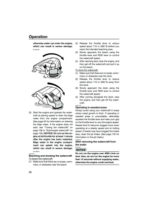 92
92 93
93 94
94 95
95 96
96 97
97 98
98 99
99 100
100 101
101 102
102 103
103 104
104 105
105 106
106 107
107 108
108 109
109 110
110 111
111 112
112 113
113 114
114 115
115 116
116 117
117 Loosen the fuel filler cap and remove it.
(6) Slowly add fuel to the fuel tank.
(7) Stop filling when the fuel level reachesapproximately 50 mm (2 in) from t")
![YAMAHA FX HO 2015 Owners Manual Operation and handling requirements
63
engine, which can result in severe dam-
age.
[ECJ00554]
Electric bilge draining system
Bilge water in the engine compartment is
drawn in by the operation of the](/manual-img/51/49759/w960_49759-68.png "YAMAHA FX HO 2015 Owners Manual Operation and handling requirements
63
engine, which can result in severe dam-
age.
[ECJ00554]
Electric bilge draining system
Bilge water in the engine compartment is
drawn in by the operation of the")

