2015 YAMAHA FJR1300AE lights
[x] Cancel search: lightsPage 46 of 122

INSTRUMENT AND CONTROL FUNCTIONS
3-31
3
TIPThe fuel tank cap cannot be closed un-
less the key is in the lock. In addition,
the key cannot be removed if the cap is
not properly closed and locked.
WARNING
EWA11092
Make sure that the fuel tank cap is
properly closed after fillin g fuel.
Leakin g fuel is a fire hazar d.
EAU13222
FuelMake sure there is sufficient gasoline in
the tank.
WARNING
EWA10882
Gasoline an d g asoline vapors are
extremely flammab le. To avoid fires
an d explosions an d to re duce the
risk of injury when refuelin g, follow
these instructions.1. Before refueling, turn off the en- gine and be sure that no one is sit-
ting on the vehicle. Never refuel
while smoking, or while in the vi-
cinity of sparks, open flames, or
other sources of ignition such as
the pilot lights of water heaters
and clothes dryers.
2. Do not overfill the fuel tank. When refueling, be sure to insert the
pump nozzle into the fuel tank filler
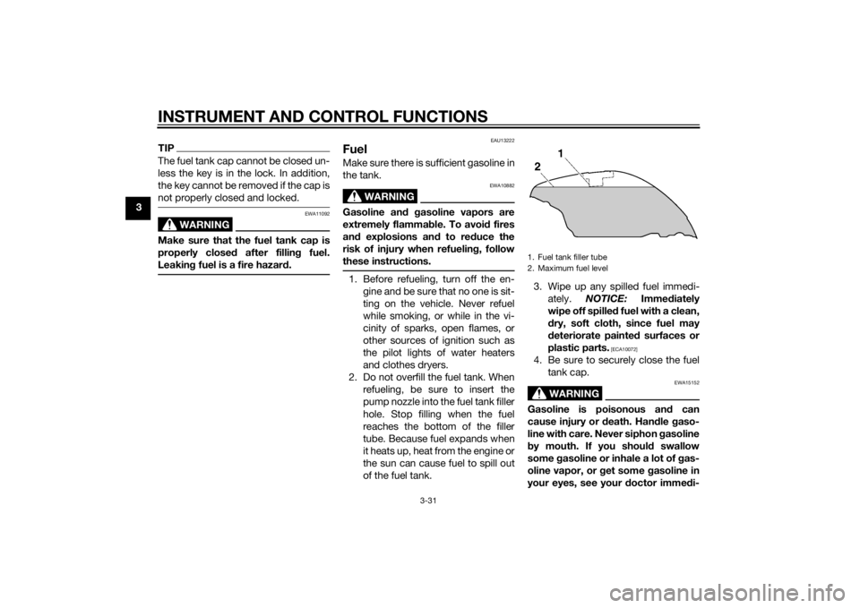
hole. Stop filling when the fuel
reaches the bottom of the filler
tube. Because fuel expands when
it heats up, heat from the engine or
the sun can cause fuel to spill out
of the fuel tank. 3. Wipe up any spilled fuel immedi-
ately. NOTICE: Immediately
wipe off spille d fuel with a clean,
d ry, soft cloth, since fuel may
d eteriorate painted surfaces or
plastic parts.
[ECA10072]
4. Be sure to securely close the fuel tank cap.
WARNING
EWA15152
Gasoline is poisonous an d can
cause injury or death. Han dle gaso-
line with care. Never siphon gasoline
b y mouth. If you should swallow
some gasoline or inhale a lot of g as-
oline vapor, or g et some gasoline in
your eyes, see your doctor imme di-1. Fuel tank filler tube
2. Maximum fuel level
U2PDE1E0.book Page 31 Thursday, July 10, 2014 5:19 PM
Page 53 of 122

INSTRUMENT AND CONTROL FUNCTIONS
3-38
3
EAU39612
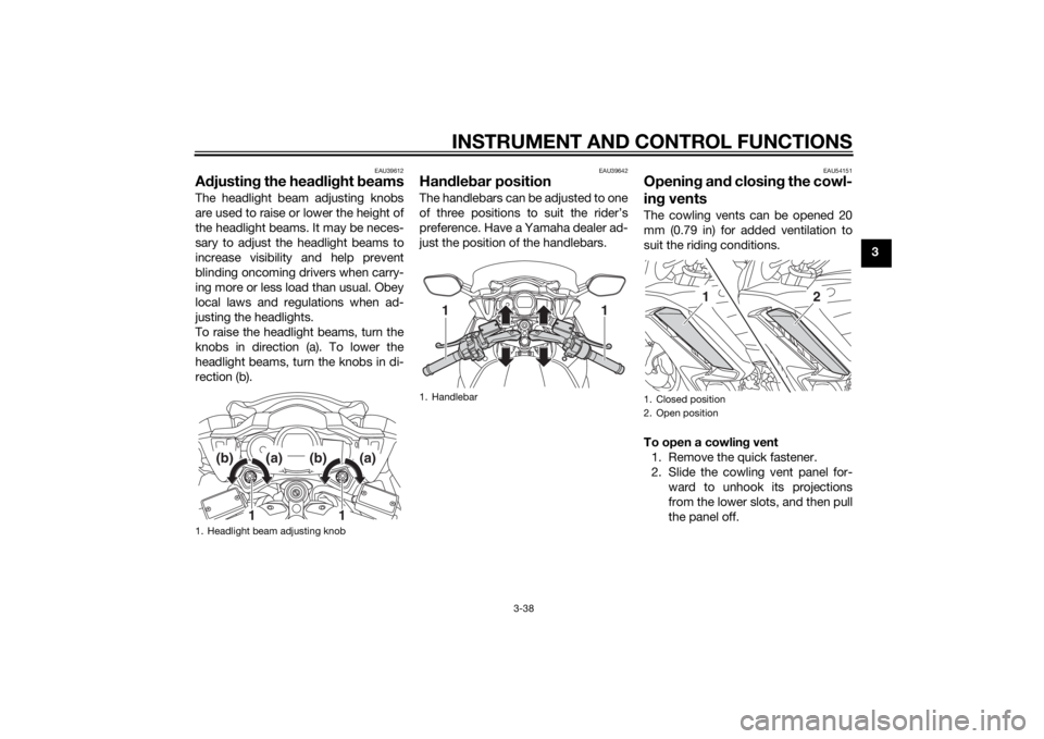
Adjustin g the hea dlig ht beamsThe headlight beam adjusting knobs
are used to raise or lower the height of
the headlight beams. It may be neces-
sary to adjust the headlight beams to
increase visibility and help prevent
blinding oncoming drivers when carry-
ing more or less load than usual. Obey
local laws and regulations when ad-
justing the headlights.
To raise the headlight beams, turn the
knobs in direction (a). To lower the
headlight beams, turn the knobs in di-
rection (b).
EAU39642
Han dle bar positionThe handlebars can be adjusted to one
of three positions to suit the rider’s
preference. Have a Yamaha dealer ad-
just the position of the handlebars.
EAU54151
Openin g an d closin g the cowl-
in g ventsThe cowling vents can be opened 20
mm (0.79 in) for added ventilation to
suit the riding conditions.
To open a cowlin g vent
1. Remove the quick fastener.
2. Slide the cowling vent panel for- ward to unhook its projections
from the lower slots, and then pull
the panel off.
1. Headlight beam adjusting knob
1
1
(b)
(a)
(b)
(a)
1. Handlebar
11
1. Closed position
2. Open position
1
2
U2PDE1E0.book Page 38 Thursday, July 10, 2014 5:19 PM
Page 65 of 122

FOR YOUR SAFETY – PRE-OPERATION CHECKS
4-3
4
Instruments, lights, si gnals
an d switches • Check operation.
• Correct if necessary.
—
Si destan d switch • Check operation of ignition circuit cut-off system.
• If system is not working correctly, have Yamaha dealer check vehicle.
3-44
ITEM CHECKS PAGE
U2PDE1E0.book Page 3 Thursday, July 10, 2014 5:19 PM
Page 66 of 122

OPERATION AND IMPORTANT RIDING POINTS
5-1
5
EAU15952
Read the Owner’s Manual carefully to
become familiar with all controls. If
there is a control or function you do not
understand, ask your Yamaha dealer.
WARNING
EWA10272
Failure to familiarize yourself with
the controls can lead to loss of con-
trol, which coul d cause an acci dent
or injury.
EAU48712
TIPThis model is equipped with: a lean angle sensor to stop the en-
gine in case of a turnover. In this
case, the display will indicate error
code 30, but this is not a malfunc-
tion. Turn the key to “OFF” and
then to “ON” to clear the error
code. Failing to do so will prevent
the engine from starting even
though the engine will crank when
pushing the start switch.
an engine auto-stop system. The
engine stops automatically if left
idling for 20 minutes. If the engine
stops, simply push the start
switch to restart the engine.
EAU58240
Startin g the en gineIn order for the ignition circuit cut-off
system to enable starting, one of the
following conditions must be met:
The transmission is in the neutral
position.
The transmission is in gear with
the clutch lever pulled and the
sidestand up.
See page 3-45 for more informa-
tion.
1. Turn the key to “ON” and make sure that the start/engine stop
switch is set to “ ”.
The following warning lights and
indicator lights should come on for
a few seconds, then go off. Oil level warning light
Engine trouble warning light
Traction control system indi-
cator/warning light
Cruise control indicator lights
Electronically adjustable sus-
pension system warning light
Immobilizer system indicator
light
U2PDE1E0.book Page 1 Thursday, July 10, 2014 5:19 PM
Page 68 of 122

OPERATION AND IMPORTANT RIDING POINTS
5-3
5
NOTICE
ECA10261
Even with the transmission in
the neutral position, do not
coast for lon g period s of time
with the en gine off, an d d o not
tow the motorcycle for lon g d is-
tances. The transmission is
properly lu bricated only when
the en gine is runnin g. Ina de-
quate lu brication may damag e
the transmission.
Always use the clutch while
chan gin g g ears to avoi d d am-
a g in g the en gine, transmission,
an d d rive train, which are not
d esi gne d to withstan d the
shock of force d shifting .
EAU16811
Tips for re ducin g fuel con-
sumptionFuel consumption depends largely on
your riding style. Consider the follow-
ing tips to reduce fuel consumption:
Shift up swiftly, and avoid high en-
gine speeds during acceleration.
Do not rev the engine while shift-
ing down, and avoid high engine
speeds with no load on the en-
gine.
Turn the engine off instead of let-
ting it idle for an extended length
of time (e.g., in traffic jams, at traf-
fic lights or at railroad crossings).
EAU16842
Engine break-inThere is never a more important period
in the life of your engine than the period
between 0 and 1600 km (1000 mi). For
this reason, you should read the fol-
lowing material carefully.
Since the engine is brand new, do not
put an excessive load on it for the first
1600 km (1000 mi). The various parts in
the engine wear and polish themselves
to the correct operating clearances.
During this period, prolonged full-throt-
tle operation or any condition that
might result in engine overheating
must be avoided.
EAU17124
0–1000 km (0–600 mi)
Avoid prolonged operation above 4500
r/min. NOTICE: After 1000 km (600
mi) of operation, the en gine oil an d
final gear oil must be chan ged , an d
the oil filter cartri dge or element re-
placed .
[ECA10333]
U2PDE1E0.book Page 3 Thursday, July 10, 2014 5:19 PM
Page 103 of 122

PERIODIC MAINTENANCE AND ADJUSTMENT
6-34
6
EAU54501
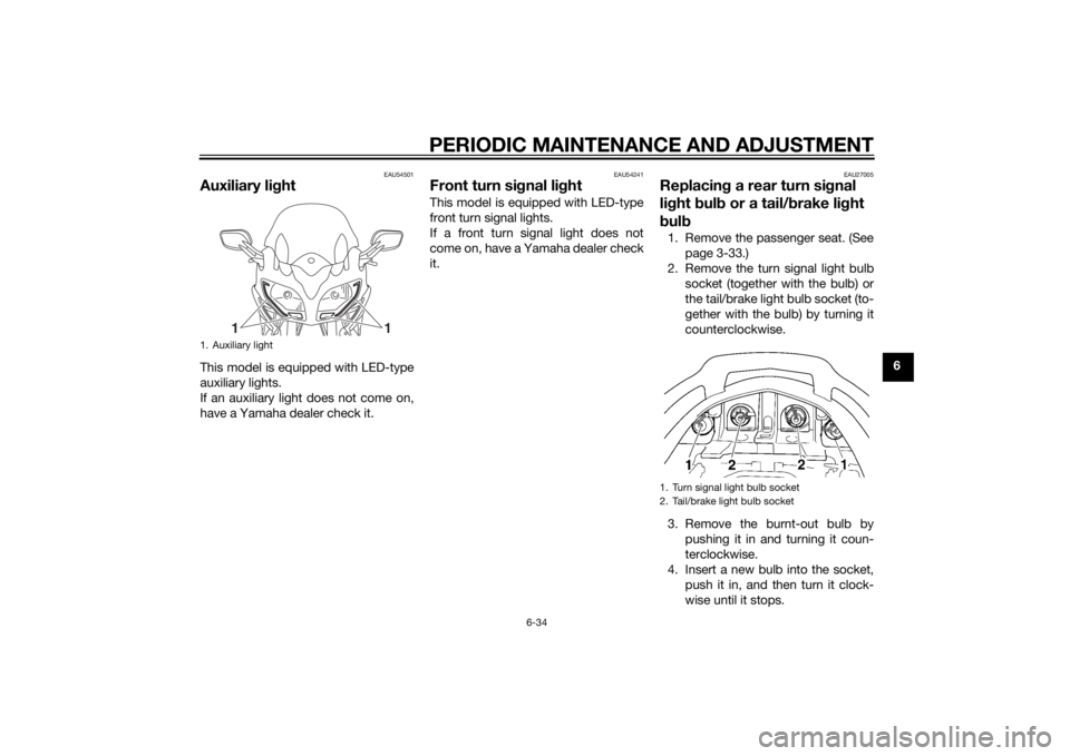
Auxiliary lightThis model is equipped with LED-type
auxiliary lights.
If an auxiliary light does not come on,
have a Yamaha dealer check it.
EAU54241
Front turn si gnal li ghtThis model is equipped with LED-type
front turn signal lights.
If a front turn signal light does not
come on, have a Yamaha dealer check
it.
EAU27005
Replacin g a rear turn si gnal
lig ht bul b or a tail/ brake li ght
b ul b1. Remove the passenger seat. (See
page 3-33.)
2. Remove the turn signal light bulb socket (together with the bulb) or
the tail/brake light bulb socket (to-
gether with the bulb) by turning it
counterclockwise.
3. Remove the burnt-out bulb by pushing it in and turning it coun-
terclockwise.
4. Insert a new bulb into the socket, push it in, and then turn it clock-
wise until it stops.
1. Auxiliary light
1
1
1. Turn signal light bulb socket
2. Tail/brake light bulb socket
U2PDE1E0.book Page 34 Thursday, July 10, 2014 5:19 PM
Page 118 of 122

10-1
10
INDEXAABS ....................................................... 3-28
ABS warning light ................................... 3-5
Accessory box ...................................... 3-37
Air filter element, cleaning .................... 6-17
Auxiliary DC jack ................................... 3-47
Auxiliary light......................................... 6-34BBattery .................................................. 6-30
Brake and clutch fluid levels, checking ............................................. 6-24
Brake and clutch fluids, changing ........ 6-25
Brake and clutch levers, checking and lubricating ........................................... 6-27
Brake and shift pedals, checking and
lubricating ........................................... 6-26
Brake lever ............................................ 3-27
Brake lever free play, checking............. 6-22
Brake light switches.............................. 6-23
Brake pedal........................................... 3-27CCables, checking and lubricating ......... 6-26
Care ........................................................ 7-1
Catalytic converters .............................. 3-32
Centerstand and sidestand, checking and lubricating .................................... 6-28
Clutch lever ................................. 3-26, 6-22
Coolant ................................................. 6-16
Cowling vents, opening and closing ..... 3-38
Cruise control indicator lights ................. 3-4
Cruise control switches ........................ 3-25
Cruise control system ............................. 3-7DDimmer/Pass switch ............................. 3-25 D-mode (drive mode) ........................... 3-24
EElectronically adjustable suspension
system warning light ............................ 3-6
Engine break-in ...................................... 5-3
Engine idling speed, checking ............. 6-18
Engine oil and oil filter cartridge ........... 6-12
Engine serial number .............................. 9-1
Engine trouble warning light ................... 3-5FFinal gear oil ......................................... 6-14
Front and rear brake pads, checking ... 6-23
Front fork, checking ............................. 6-29
Front turn signal light............................ 6-34
Fuel ....................................................... 3-31
Fuel consumption, tips for reducing ...... 5-3
Fuel tank breather/overflow hose ......... 3-32
Fuel tank cap ........................................ 3-30
Fuses, replacing ................................... 6-32HHandlebar position, adjusting .............. 3-38
Handlebar switches .............................. 3-24
Hazard switch....................................... 3-25
Headlight beams, adjusting.................. 3-38
Headlight bulb ...................................... 6-33
High beam indicator light ....................... 3-4
Horn switch .......................................... 3-25IIdentification numbers ............................ 9-1
Ignition circuit cut-off system ............... 3-45
Immobilizer system ................................ 3-1
Immobilizer system indicator light .......... 3-6
Indicator lights and warning lights ......... 3-4
LLicense plate light bulb, replacing ........6-35MMain switch/steering lock .......................3-2
Maintenance and lubrication, periodic....6-4
Maintenance, emission control system ..................................................6-3
Matte color, caution ................................7-1
Menu switch..........................................3-25
Model label .............................................9-1
Multi-function meter unit .......................3-10NNeutral indicator light ..............................3-4OOil level warning light ..............................3-4PPanels, removing and installing ..............6-8
Parking ....................................................5-4
Part locations ..........................................2-1RRear suspension, lubricating ................6-28
Rear view mirrors ..................................3-40
Rider seat height, adjusting ..................3-34SSafety information ...................................1-1
Seats .....................................................3-33
Select switch.........................................3-26
Shifting ....................................................5-2
Shift pedal .............................................3-27
Sidestand ..............................................3-44
Spark plugs, checking ..........................6-11
Specifications .........................................8-1
Start/Engine stop switch .......................3-25
Starting the engine ..................................5-1
U2PDE1E0.book Page 1 Thursday, July 10, 2014 5:19 PM
Page 119 of 122

INDEX
10-2
10
Steering, checking ................................ 6-30
Storage ................................................... 7-4
Storage compartments......................... 3-36
Suspension, adjusting the front and rear ..................................................... 3-40
Swingarm pivots, lubricating ................ 6-29TThrottle grip and cable, checking and lubricating........................................... 6-26
Throttle grip free play, checking ........... 6-19
Tires ...................................................... 6-19
Tool kit .................................................... 6-2
Traction control system ........................ 3-29
Traction control system indicator/ warning light ......................................... 3-5
Troubleshooting.................................... 6-36
Troubleshooting charts......................... 6-37
Turn signal indicator lights ..................... 3-4
Turn signal light or tail/brake light bulb,
replacing............................................. 6-34
Turn signal switch................................. 3-25VValve clearance .................................... 6-19
Vehicle identification number ................. 9-1WWheel bearings, checking .................... 6-30
Wheels .................................................. 6-22
U2PDE1E0.book Page 2 Thursday, July 10, 2014 5:19 PM