2015 YAMAHA FJR1300AE cruise control
[x] Cancel search: cruise controlPage 41 of 122

INSTRUMENT AND CONTROL FUNCTIONS
3-26
3
EAU54221
Select switch “ / ”
This switch is used to perform selec-
tions in the function display and setting
mode display of the multi-function me-
ter unit.
See “Multi-function meter unit” on
page 3-10 for detailed information.
EAU54691
Drive mode switch “MODE”
WARNING
EWA15341
Do not chan ge the D-mod e while the
vehicle is movin g.Using this switch changes the drive
mode to touring mode “T” or sports
mode “S”.
The throttle grip must be completely
closed in order to change the drive
mode.
The selected mode is shown on the
drive mode display. (See page 3-12.)
The drive mode cannot be changed
while the cruise control system is oper-
ating.
EAU12831
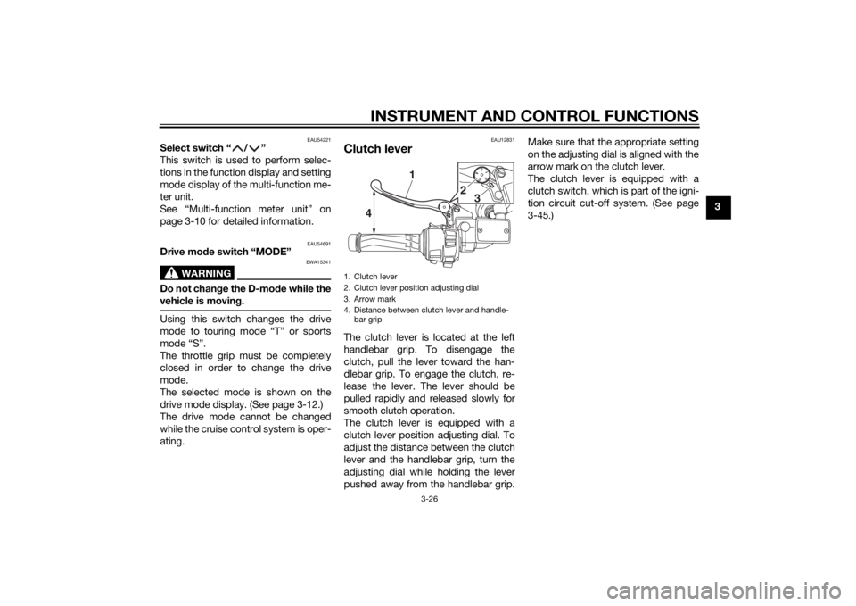
Clutch leverThe clutch lever is located at the left
handlebar grip. To disengage the
clutch, pull the lever toward the han-
dlebar grip. To engage the clutch, re-
lease the lever. The lever should be
pulled rapidly and released slowly for
smooth clutch operation.
The clutch lever is equipped with a
clutch lever position adjusting dial. To
adjust the distance between the clutch
lever and the handlebar grip, turn the
adjusting dial while holding the lever
pushed away from the handlebar grip. Make sure that the appropriate setting
on the adjusting dial is aligned with the
arrow mark on the clutch lever.
The clutch lever is equipped with a
clutch switch, which is part of the igni-
tion circuit cut-off system. (See page
3-45.)1. Clutch lever
2. Clutch lever position adjusting dial
3. Arrow mark
4. Distance between clutch lever and handle-
bar grip
15432
4 1
2
3
U2PDE1E0.book Page 26 Thursday, July 10, 2014 5:19 PM
Page 66 of 122

OPERATION AND IMPORTANT RIDING POINTS
5-1
5
EAU15952
Read the Owner’s Manual carefully to
become familiar with all controls. If
there is a control or function you do not
understand, ask your Yamaha dealer.
WARNING
EWA10272
Failure to familiarize yourself with
the controls can lead to loss of con-
trol, which coul d cause an acci dent
or injury.
EAU48712
TIPThis model is equipped with: a lean angle sensor to stop the en-
gine in case of a turnover. In this
case, the display will indicate error
code 30, but this is not a malfunc-
tion. Turn the key to “OFF” and
then to “ON” to clear the error
code. Failing to do so will prevent
the engine from starting even
though the engine will crank when
pushing the start switch.
an engine auto-stop system. The
engine stops automatically if left
idling for 20 minutes. If the engine
stops, simply push the start
switch to restart the engine.
EAU58240
Startin g the en gineIn order for the ignition circuit cut-off
system to enable starting, one of the
following conditions must be met:
The transmission is in the neutral
position.
The transmission is in gear with
the clutch lever pulled and the
sidestand up.
See page 3-45 for more informa-
tion.
1. Turn the key to “ON” and make sure that the start/engine stop
switch is set to “ ”.
The following warning lights and
indicator lights should come on for
a few seconds, then go off. Oil level warning light
Engine trouble warning light
Traction control system indi-
cator/warning light
Cruise control indicator lights
Electronically adjustable sus-
pension system warning light
Immobilizer system indicator
light
U2PDE1E0.book Page 1 Thursday, July 10, 2014 5:19 PM
Page 92 of 122

PERIODIC MAINTENANCE AND ADJUSTMENT
6-23
6b
rakin g performance, which may re-
sult in loss of control and an acci-
d ent.
EAU22283
Brake li ght switchesThe brake light, which is activated by
the brake pedal and brake lever,
should come on just before braking
takes effect. Since the brake light
switches are components of the cruise
control system, they must be adjusted
by a Yamaha dealer, who has the nec-
essary professional knowledge and ex-
perience.
EAU22393
Checkin g the front an d rear
b rake pa dsThe front and rear brake pads must be
checked for wear at the intervals spec-
ified in the periodic maintenance and
lubrication chart.
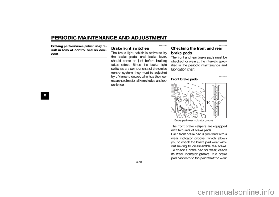
EAU43432
Front brake pa ds
The front brake calipers are equipped
with two sets of brake pads.
Each front brake pad is provided with a
wear indicator groove, which allows
you to check the brake pad wear with-
out having to disassemble the brake.
To check a brake pad for wear, check
its wear indicator groove. If a brake
pad has worn to the point that the wear1. Brake pad wear indicator groove
1
1
U2PDE1E0.book Page 23 Thursday, July 10, 2014 5:19 PM
Page 101 of 122

PERIODIC MAINTENANCE AND ADJUSTMENT
6-32
6
EAU54513
Replacing the fusesThe fuse boxes and individual fuses
are located under panel A. (See page
6-8.)
If a fuse is blown, replace it as follows.1. Turn the key to “OFF” and turn off the electrical circuit in question. 2. Remove the blown fuse, and then
install a new fuse of the specified
amperage. WARNING! Do not
use a fuse of a hi gher ampera ge
ratin g than recommen ded to
avoi d causin g extensive dam-
a g e to the electrical system an d
possi bly a fire.
[EWA15132]
1. Main fuse 1
2. Spare fuse
3. Cruise control fuse
4. Brake light fuse
5. Fuse box
6. Main fuse 2
5
1
3
4
2
5 26
1. ABS motor fuse
2. ABS solenoid fuse
3. Fuel injection system fuse
4. Backup fuse (for clock and immobilizer sys-
tem)
5. Electronic throttle valve fuse
6. Headlight fuse
7. Spare fuse
8. Suspension fuse
9. Signaling system fuse
10.Auxiliary DC jack fuse
11.ABS control unit fuse
12.Ignition fuse
13.Right radiator fan motor fuse
14.Left radiator fan motor fuse
15.Hazard fuse
16.Windshield motor fuse817
2
3456
7
14
7
10 91112
13
7
16
15
U2PDE1E0.book Page 32 Thursday, July 10, 2014 5:19 PM
Page 102 of 122

PERIODIC MAINTENANCE AND ADJUSTMENT
6-33
63. Turn the key to “ON” and turn on
the electrical circuit in question to
check if the device operates.
4. If the fuse immediately blows again, have a Yamaha dealer
check the electrical system.
EAU40362
Hea dlig ht bul bIf a headlight does not come on, have
a Yamaha dealer check its electrical
circuit or replace the bulb.NOTICE
ECA16581
Do not affix any type of tinte d film or
stickers to the hea dlig ht lens.
Specifie d fuses:
Main fuse 1:
50.0 A
Main fuse 2:
30.0 A
Headlight fuse: 25.0 A
Brake light fuse: 1.0 A
Signaling system fuse:
10.0 A
Ignition fuse: 20.0 A
Radiator fan motor fuse: 10.0 A × 2
Backup fuse:
7.5 A
Hazard fuse: 7.5 A
Fuel injection system fuse: 15.0 A
ABS control unit fuse:
7.5 A
ABS motor fuse: 30.0 A
ABS solenoid fuse: 20.0 A
Suspension fuse:
15.0 A
Cruise control fuse: 1.0 A
Auxiliary DC jack fuse: 3.0 A
Windshield motor fuse:20.0 A
Electronic throttle valve fuse: 7.5 A
U2PDE1E0.book Page 33 Thursday, July 10, 2014 5:19 PM
Page 115 of 122

SPECIFICATIONS
8-3
8
Wheel travel:125 mm (4.9 in)Electrical system:Ignition system:
TCI
Charging system: AC magnetoBattery:Model:
GT14B-4
Voltage, capacity: 12 V, 12.0 AhHea dlig ht:Bulb type:
Halogen bulbBul b volta ge, watta ge × quantity:Headlight:
12 V, 60.0 W/55.0 W × 2
Tail/brake light:
12 V, 5.0 W/21.0 W × 2
Front turn signal light: LED
Rear turn signal light: 12 V, 21.0 W × 2
Auxiliary light:
LED
License plate light: 12 V, 5.0 W × 1
Meter lighting: LED
Neutral indicator light:
LED
High beam indicator light: LED Oil level warning light:
LED
Turn signal indicator light: LED
Engine trouble warning light:
LED
ABS warning light: LED
Cruise control “SET” indicator light: LED
Cruise control “ON” indicator light:
LED
Immobilizer system indicator light: LED
Traction control system indicator/warning
light: LED
Suspension warning light: LED
Fuses:Main fuse 1:50.0 A
Main fuse 2: 30.0 A
Headlight fuse:
25.0 A
Brake light fuse: 1.0 A
Signaling system fuse: 10.0 A
Ignition fuse:
20.0 A
Radiator fan motor fuse: 10.0 A × 2 Hazard fuse:
7.5 A
Fuel injection system fuse: 15.0 A
ABS control unit fuse:
7.5 A
ABS motor fuse: 30.0 A
ABS solenoid fuse: 20.0 A
Suspension fuse:
15.0 A
Cruise control fuse: 1.0 A
Auxiliary DC jack fuse: 3.0 A
Backup fuse:
7.5 A
Windshield motor fuse: 20.0 A
Electronic throttle valve fuse: 7.5 A
U2PDE1E0.book Page 3 Thursday, July 10, 2014 5:19 PM
Page 118 of 122

10-1
10
INDEXAABS ....................................................... 3-28
ABS warning light ................................... 3-5
Accessory box ...................................... 3-37
Air filter element, cleaning .................... 6-17
Auxiliary DC jack ................................... 3-47
Auxiliary light......................................... 6-34BBattery .................................................. 6-30
Brake and clutch fluid levels, checking ............................................. 6-24
Brake and clutch fluids, changing ........ 6-25
Brake and clutch levers, checking and lubricating ........................................... 6-27
Brake and shift pedals, checking and
lubricating ........................................... 6-26
Brake lever ............................................ 3-27
Brake lever free play, checking............. 6-22
Brake light switches.............................. 6-23
Brake pedal........................................... 3-27CCables, checking and lubricating ......... 6-26
Care ........................................................ 7-1
Catalytic converters .............................. 3-32
Centerstand and sidestand, checking and lubricating .................................... 6-28
Clutch lever ................................. 3-26, 6-22
Coolant ................................................. 6-16
Cowling vents, opening and closing ..... 3-38
Cruise control indicator lights ................. 3-4
Cruise control switches ........................ 3-25
Cruise control system ............................. 3-7DDimmer/Pass switch ............................. 3-25 D-mode (drive mode) ........................... 3-24
EElectronically adjustable suspension
system warning light ............................ 3-6
Engine break-in ...................................... 5-3
Engine idling speed, checking ............. 6-18
Engine oil and oil filter cartridge ........... 6-12
Engine serial number .............................. 9-1
Engine trouble warning light ................... 3-5FFinal gear oil ......................................... 6-14
Front and rear brake pads, checking ... 6-23
Front fork, checking ............................. 6-29
Front turn signal light............................ 6-34
Fuel ....................................................... 3-31
Fuel consumption, tips for reducing ...... 5-3
Fuel tank breather/overflow hose ......... 3-32
Fuel tank cap ........................................ 3-30
Fuses, replacing ................................... 6-32HHandlebar position, adjusting .............. 3-38
Handlebar switches .............................. 3-24
Hazard switch....................................... 3-25
Headlight beams, adjusting.................. 3-38
Headlight bulb ...................................... 6-33
High beam indicator light ....................... 3-4
Horn switch .......................................... 3-25IIdentification numbers ............................ 9-1
Ignition circuit cut-off system ............... 3-45
Immobilizer system ................................ 3-1
Immobilizer system indicator light .......... 3-6
Indicator lights and warning lights ......... 3-4
LLicense plate light bulb, replacing ........6-35MMain switch/steering lock .......................3-2
Maintenance and lubrication, periodic....6-4
Maintenance, emission control system ..................................................6-3
Matte color, caution ................................7-1
Menu switch..........................................3-25
Model label .............................................9-1
Multi-function meter unit .......................3-10NNeutral indicator light ..............................3-4OOil level warning light ..............................3-4PPanels, removing and installing ..............6-8
Parking ....................................................5-4
Part locations ..........................................2-1RRear suspension, lubricating ................6-28
Rear view mirrors ..................................3-40
Rider seat height, adjusting ..................3-34SSafety information ...................................1-1
Seats .....................................................3-33
Select switch.........................................3-26
Shifting ....................................................5-2
Shift pedal .............................................3-27
Sidestand ..............................................3-44
Spark plugs, checking ..........................6-11
Specifications .........................................8-1
Start/Engine stop switch .......................3-25
Starting the engine ..................................5-1
U2PDE1E0.book Page 1 Thursday, July 10, 2014 5:19 PM