Page 97 of 122
PERIODIC MAINTENANCE AND ADJUSTMENT
6-28
6
EAU23215
Checking an d lu bricatin g the
centerstan d an d si destan dThe operation of the centerstand and
sidestand should be checked before
each ride, and the pivots and metal-to-
metal contact surfaces should be lubri-
cated if necessary.
WARNING
EWA10742
If the centerstan d or si destan d d oes
not move up an d d own smoothly,
have a Yamaha d ealer check or re-
pair it. Otherwise, the centerstan d or
si destan d coul d contact the g round
an d d istract the operator, resultin g
in a possib le loss of control.
EAU23252
Lubricatin g the rear suspen-
sionThe pivoting points of the rear suspen-
sion must be lubricated by a Yamaha
dealer at the intervals specified in the
periodic maintenance and lubrication
chart.
Recommen ded lu bricant:
Lithium-soap-based grease
Recommen ded lu bricant:
Lithium-soap-based grease
U2PDE1E0.book Page 28 Thursday, July 10, 2014 5:19 PM
Page 98 of 122

PERIODIC MAINTENANCE AND ADJUSTMENT
6-29
6
EAUM1653
Lubricatin g the swin garm piv-
otsThe swingarm pivots must be lubricat-
ed by a Yamaha dealer at the intervals
specified in the periodic maintenance
and lubrication chart.
EAU23273
Checkin g the front forkThe condition and operation of the
front fork must be checked as follows
at the intervals specified in the periodic
maintenance and lubrication chart.
To check the con dition
Check the inner tubes for scratches,
damage and excessive oil leakage.
To check the operation 1. Place the vehicle on a level sur- face and hold it in an upright posi-
tion. WARNING! To avoi d injury,
securely support the vehicle so
there is no dan ger of it fallin g
over.
[EWA10752]
2. While applying the front brake, push down hard on the handle-
bars several times to check if the
front fork compresses and re-
bounds smoothly.
NOTICE
ECA10591
If any d amage is foun d or the front
fork does not operate smoothly,
have a Yamaha dealer check or re-
pair it.
Recommen ded lu bricant:
Lithium-soap-based grease
U2PDE1E0.book Page 29 Thursday, July 10, 2014 5:19 PM
Page 99 of 122

PERIODIC MAINTENANCE AND ADJUSTMENT
6-30
6
EAU45512
Checking the steerin gWorn or loose steering bearings may
cause danger. Therefore, the operation
of the steering must be checked as fol-
lows at the intervals specified in the
periodic maintenance and lubrication
chart.
1. Place the vehicle on the center- stand. WARNING! To avoi d inju-
ry, securely support the vehicle
so there is no d anger of it fallin g
over.
[EWA10752]
2. Hold the lower ends of the front fork legs and try to move them for-
ward and backward. If any free
play can be felt, have a Yamaha
dealer check or repair the steer-
ing.
EAU23292
Checkin g the wheel bearin gsThe front and rear wheel bearings must
be checked at the intervals specified in
the periodic maintenance and lubrica-
tion chart. If there is play in the wheel
hub or if the wheel does not turn
smoothly, have a Yamaha dealer
check the wheel bearings.
EAU39526
BatteryThe battery is located under panel A.
(See page 6-8.)
This model is equipped with a VRLA
(Valve Regulated Lead Acid) battery.
There is no need to check the electro-
lyte or to add distilled water. However,
the battery lead connections need to
be checked and, if necessary, tight-
ened.
WARNING
EWA10761
Electrolyte is poisonous an d
d an gerous since it contains sul-
furic aci d, which causes severe1. Battery
2. Positive battery lead (red)
3. Negative battery lead (black)
1 2
3
U2PDE1E0.book Page 30 Thursday, July 10, 2014 5:19 PM
Page 100 of 122

PERIODIC MAINTENANCE AND ADJUSTMENT
6-31
6b
urns. Avoi d any contact with
skin, eyes or clothin g an d al-
ways shiel d your eyes when
workin g near b atteries. In case
of contact, ad minister the fol-
lowin g FIRST AID.
EXTERNAL: Flush with plenty of water.
INTERNAL: Drink lar ge quan-
tities of water or milk an d im-
me diately call a physician.
EYES: Flush with water for 15 minutes an d seek prompt
me dical attention.
Batteries pro duce explosive hy-
d ro gen gas. Therefore, keep
sparks, flames, ci garettes, etc.,
away from the battery an d pro-
vi de sufficient ventilation when
char gin g it in an enclosed
space.
KEEP THIS AND ALL BATTER-
IES OUT OF THE REACH OF
CHILDREN.
To char ge the battery
Have a Yamaha dealer charge the bat-
tery as soon as possible if it seems to
have discharged. Keep in mind that the battery tends to discharge more quick-
ly if the vehicle is equipped with op-
tional electrical accessories.
NOTICE
ECA16522
To char
ge a VRLA (Valve Re gulate d
Lea d Aci d) battery, a special (con-
stant-voltag e) battery char ger is re-
quired . Using a conventional b attery
char ger will damag e the b attery.To store the battery
1. If the vehicle will not be used for more than one month, remove the
battery, fully charge it, and then
place it in a cool, dry place.
NOTICE: When removin g the
b attery, be sure the key is
turne d to “OFF”, then d iscon-
nect the neg ative lead b efore
d isconnectin g the positive lea d.
[ECA16303]
2. If the battery will be stored for
more than two months, check it at
least once a month and fully
charge it if necessary.
3. Fully charge the battery before in- stallation. NOTICE: When install-
in g the b attery, be sure the key is turned
to “OFF”, then connect
the positive lea d before con-
nectin g the ne gative lea d.
[ECA16841]
4. After installation, make sure that
the battery leads are properly con-
nected to the battery terminals.NOTICE
ECA16531
Always keep the b attery charged .
Storin g a d ischar ged battery can
cause permanent b attery damag e.
U2PDE1E0.book Page 31 Thursday, July 10, 2014 5:19 PM
Page 101 of 122

If a fuse is blown, replace it as follows.1. Turn")
PERIODIC MAINTENANCE AND ADJUSTMENT
6-32
6
EAU54513
Replacing the fusesThe fuse boxes and individual fuses
are located under panel A. (See page
6-8.)
If a fuse is blown, replace it as follows.1. Turn the key to “OFF” and turn off the electrical circuit in question. 2. Remove the blown fuse, and then
install a new fuse of the specified
amperage. WARNING! Do not
use a fuse of a hi gher ampera ge
ratin g than recommen ded to
avoi d causin g extensive dam-
a g e to the electrical system an d
possi bly a fire.
[EWA15132]
1. Main fuse 1
2. Spare fuse
3. Cruise control fuse
4. Brake light fuse
5. Fuse box
6. Main fuse 2
5
1
3
4
2
5 26
1. ABS motor fuse
2. ABS solenoid fuse
3. Fuel injection system fuse
4. Backup fuse (for clock and immobilizer sys-
tem)
5. Electronic throttle valve fuse
6. Headlight fuse
7. Spare fuse
8. Suspension fuse
9. Signaling system fuse
10.Auxiliary DC jack fuse
11.ABS control unit fuse
12.Ignition fuse
13.Right radiator fan motor fuse
14.Left radiator fan motor fuse
15.Hazard fuse
16.Windshield motor fuse817
2
3456
7
14
7
10 91112
13
7
16
15
U2PDE1E0.book Page 32 Thursday, July 10, 2014 5:19 PM
Page 102 of 122

PERIODIC MAINTENANCE AND ADJUSTMENT
6-33
63. Turn the key to “ON” and turn on
the electrical circuit in question to
check if the device operates.
4. If the fuse immediately blows again, have a Yamaha dealer
check the electrical system.
EAU40362
Hea dlig ht bul bIf a headlight does not come on, have
a Yamaha dealer check its electrical
circuit or replace the bulb.NOTICE
ECA16581
Do not affix any type of tinte d film or
stickers to the hea dlig ht lens.
Specifie d fuses:
Main fuse 1:
50.0 A
Main fuse 2:
30.0 A
Headlight fuse: 25.0 A
Brake light fuse: 1.0 A
Signaling system fuse:
10.0 A
Ignition fuse: 20.0 A
Radiator fan motor fuse: 10.0 A × 2
Backup fuse:
7.5 A
Hazard fuse: 7.5 A
Fuel injection system fuse: 15.0 A
ABS control unit fuse:
7.5 A
ABS motor fuse: 30.0 A
ABS solenoid fuse: 20.0 A
Suspension fuse:
15.0 A
Cruise control fuse: 1.0 A
Auxiliary DC jack fuse: 3.0 A
Windshield motor fuse:20.0 A
Electronic throttle valve fuse: 7.5 A
U2PDE1E0.book Page 33 Thursday, July 10, 2014 5:19 PM
Page 103 of 122
PERIODIC MAINTENANCE AND ADJUSTMENT
6-34
6
EAU54501
Auxiliary lightThis model is equipped with LED-type
auxiliary lights.
If an auxiliary light does not come on,
have a Yamaha dealer check it.
EAU54241
Front turn si gnal li ghtThis model is equipped with LED-type
front turn signal lights.
If a front turn signal light does not
come on, have a Yamaha dealer check
it.
EAU27005
Replacin g a rear turn si gnal
lig ht bul b or a tail/ brake li ght
b ul b1. Remove the passenger seat. (See
page 3-33.)
2. Remove the turn signal light bulb socket (together with the bulb) or
the tail/brake light bulb socket (to-
gether with the bulb) by turning it
counterclockwise.
3. Remove the burnt-out bulb by pushing it in and turning it coun-
terclockwise.
4. Insert a new bulb into the socket, push it in, and then turn it clock-
wise until it stops.
1. Auxiliary light
1
1
1. Turn signal light bulb socket
2. Tail/brake light bulb socket
U2PDE1E0.book Page 34 Thursday, July 10, 2014 5:19 PM
Page 104 of 122
PERIODIC MAINTENANCE AND ADJUSTMENT
6-35
65. Install the socket (together with
the bulb) by turning it clockwise.
6. Install the passenger seat.
EAU24314
Replacin g the license plate
li g ht bul b1. Remove the license plate light unit
by removing the screws.
2. Remove the license plate light bulb socket (together with the
bulb) by pulling it out. 3. Remove the burnt-out bulb by
pulling it out.
4. Insert a new bulb into the socket.
5. Install the socket (together with the bulb) by pushing it in.
6. Install the license plate light unit by installing the screws.1. Screw
2. License plate light unit
1. License plate light bulb
2. License plate light bulb socket
1
2
U2PDE1E0.book Page 35 Thursday, July 10, 2014 5:19 PM
 1
1 2
2 3
3 4
4 5
5 6
6 7
7 8
8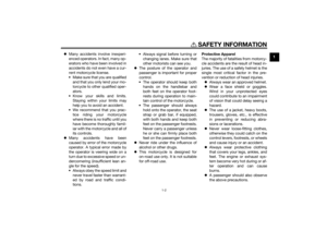 9
9 10
10 11
11 12
12 13
13 14
14 15
15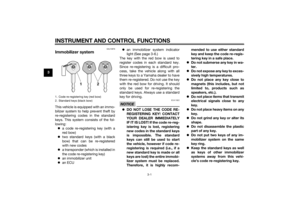 16
16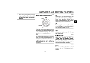 17
17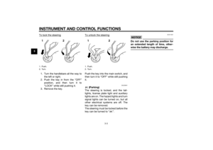 18
18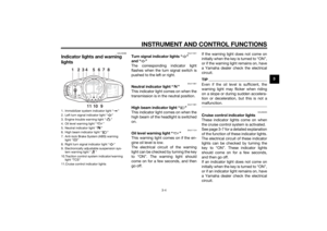 19
19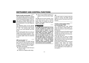 20
20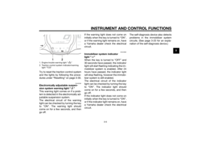 21
21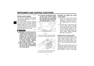 22
22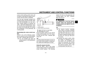 23
23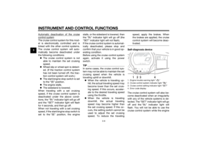 24
24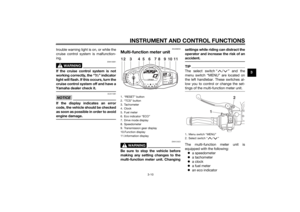 25
25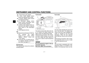 26
26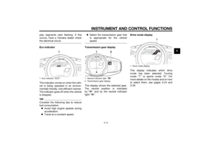 27
27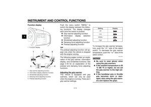 28
28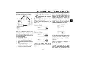 29
29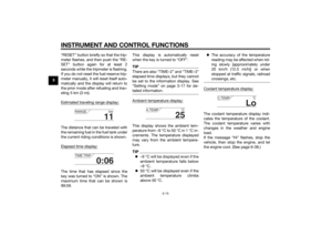 30
30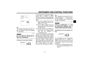 31
31 32
32 33
33 34
34 35
35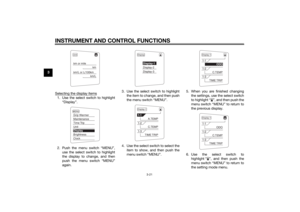 36
36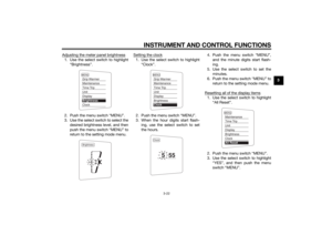 37
37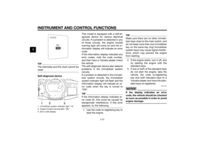 38
38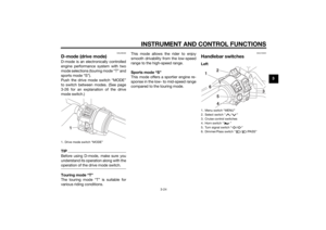 39
39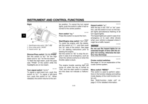 40
40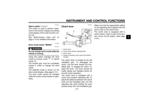 41
41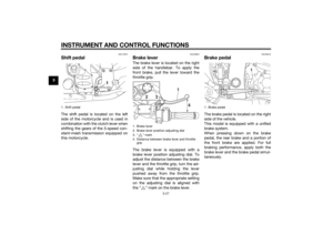 42
42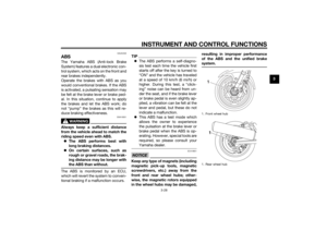 43
43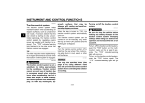 44
44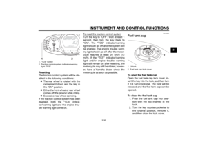 45
45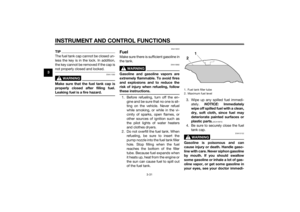 46
46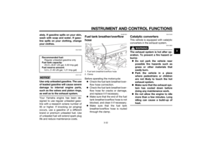 47
47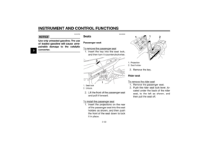 48
48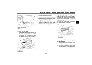 49
49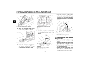 50
50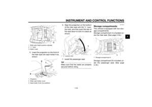 51
51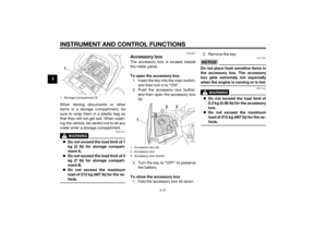 52
52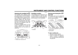 53
53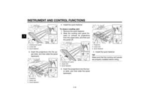 54
54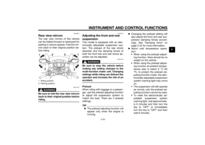 55
55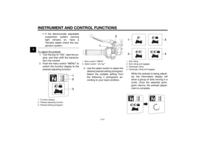 56
56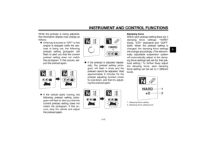 57
57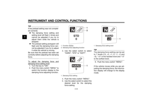 58
58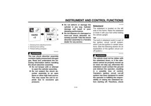 59
59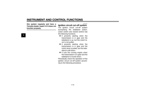 60
60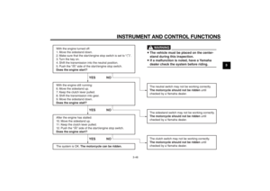 61
61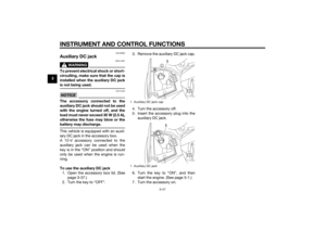 62
62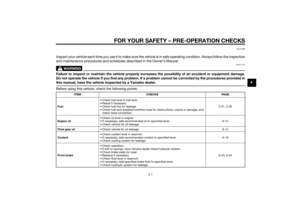 63
63 64
64 65
65 66
66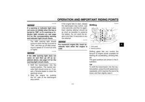 67
67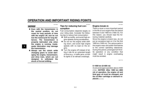 68
68 69
69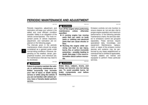 70
70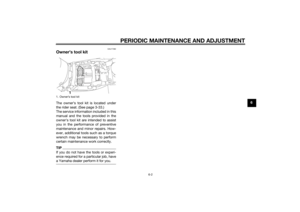 71
71 72
72 73
73 74
74 75
75 76
76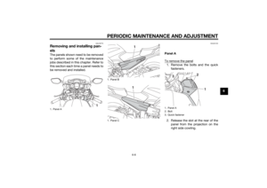 77
77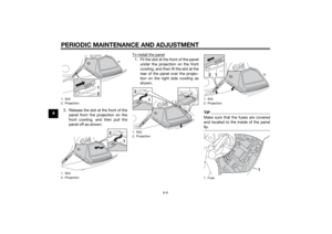 78
78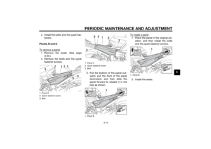 79
79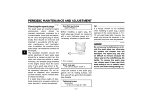 80
80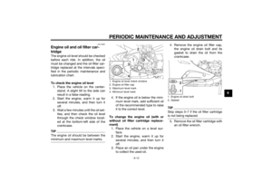 81
81 82
82 83
83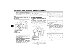 84
84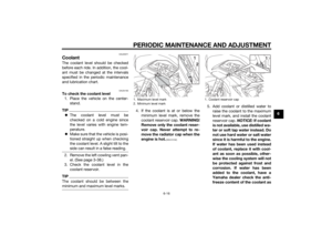 85
85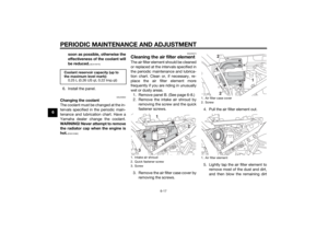 86
86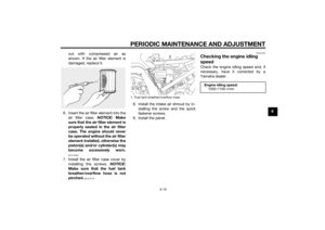 87
87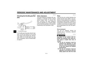 88
88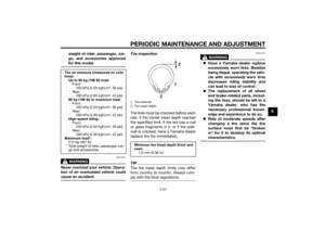 89
89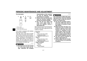 90
90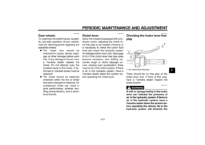 91
91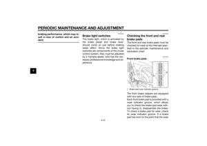 92
92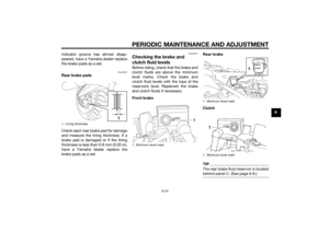 93
93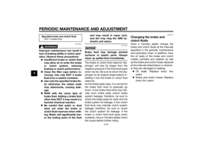 94
94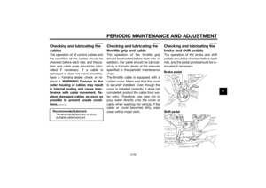 95
95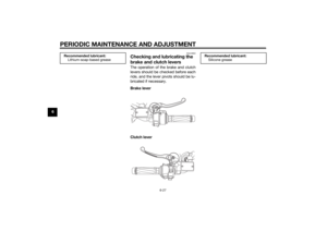 96
96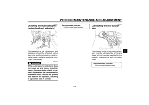 97
97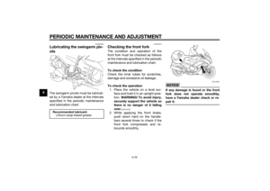 98
98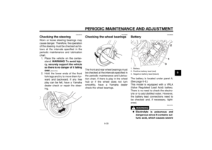 99
99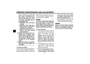 100
100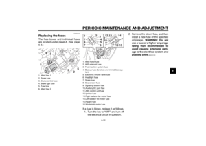 101
101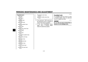 102
102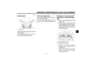 103
103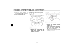 104
104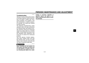 105
105 106
106 107
107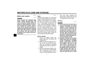 108
108 109
109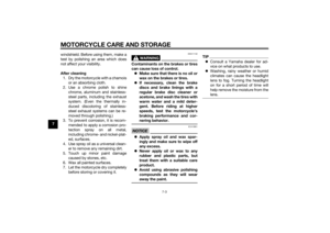 110
110 111
111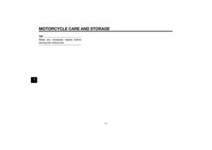 112
112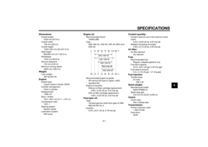 113
113 114
114 115
115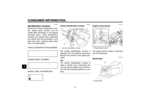 116
116 117
117 118
118 119
119 120
120 121
121

 by turning it clockwise.
6. Install the passenger seat.
EAU24314
Replacin g the license plate
li g ht bul b1.")