Page 329 of 408

08 Wheels and tires
Tire Sealing System*
08
}}
* Option/accessory, for more information, see Introduction.327
Tire sealing system–temporarily repairing a flat tire
Temporarily repairing a flat tire is done in two stages:
• Stage 1:
The hole is sealed by pumping
sealing compound into the tire. The car is then driven a short distance to distributethe sealing compound in the tire.
NOTE
Do not remove any foreign objects (nails, etc.) from the tire before using the sealingsystem.
• Stage 2:
The tire’s inflation pressure is
checked and adjusted if necessary.
WARNING
• Never leave the tire sealing system unattended when it is operating.
• Keep the tire sealing system awayfrom children.
• Be sure the vehicle is parked safely offthe road and away from moving traffic.
• Apply the parking brake.
Stage 1: Sealing the hole1. Peel off the speed limit sticker and affix it
to the steering wheel hub where it will be clearly visible to the driver.
2. Ensure that the on/off switch is in posi- tion 0 (the 0 side of the switch should be
pressed down).
WARNING
Contact with the sealing compound may cause skin irritation. If contact occurs,wash the affected area immediately withsoap and water.
3. Unscrew the orange cover over the bottle holder and unscrew the cap on the bottle of sealing compound.
NOTE
Do not break the seal on the bottle. This occurs automatically when the bottle isscrewed into the holder.
4. Screw the bottle into the bottle holder.
WARNING
The bottle is equipped with a catch to keep it securely in place and help preventsealing compound leakage. Once in place,the bottle cannot be unscrewed. This mustbe done by a trained and qualified Volvoservice technician.
5. Remove the valve cap from the tire’sinflation valve and screw the tire sealing system’s hose connector onto the valveas tightly as possible by hand.
Page 330 of 408

08 Wheels and tires
Tire Sealing System*
08
328* Option/accessory, for more information, see Introduction.
6. Connect the electrical wire to the nearest
12-volt socket in the vehicle.
NOTE
Be sure that none of the other 12-volt sockets is being used while the compres-sor is in operation.
7. Start the vehicle’s engine.
WARNING
The vehicle´s engine should be running when the tire sealing system is used toavoid battery drain. Therefore, be sure thevehicle is parked in a well ventilated place,or outdoors, before using the system.
8. Start the tire sealing system’s compres-sor by pressing the on/off switch to posi- tion I.
WARNING
• Never stand next to the tire being infla- ted when the compressor is in opera-tion.
• If cracks, bubbles, etc. form on the tire,switch off the compressor immediately.
• If there is visible damage to the sidewallor the rim, the tire cannot be repaired.The vehicle should not be driven if thisoccurs. Contact a towing service orVolvo On Call Roadside Assistance ifapplicable.
NOTE
The air pressure gauge will temporarily show an increase in pressure to approxi-mately 88 psi (6 bar) while the sealingcompound is being pumped into the tire.The pressure should return to a normallevel after approximately 30 seconds.
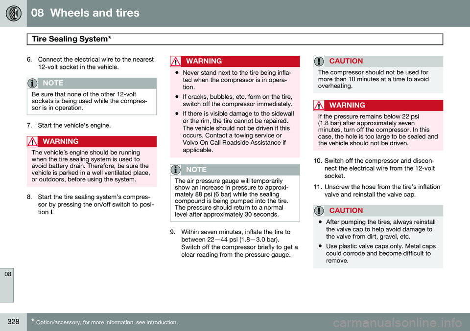
9. Within seven minutes, inflate the tire to
between 22—44 psi (1.8—3.0 bar). Switch off the compressor briefly to get aclear reading from the pressure gauge.
CAUTION
The compressor should not be used for more than 10 minutes at a time to avoidoverheating.
WARNING
If the pressure remains below 22 psi (1.8 bar) after approximately sevenminutes, turn off the compressor. In thiscase, the hole is too large to be sealed andthe vehicle should not be driven.
10. Switch off the compressor and discon- nect the electrical wire from the 12-volt socket.
11. Unscrew the hose from the tire’s inflation valve and reinstall the valve cap.
CAUTION
•After pumping the tires, always reinstall the valve cap to help avoid damage tothe valve from dirt, gravel, etc.
• Use plastic valve caps only. Metal capscould corrode and become difficult toremove.
Page 331 of 408

08 Wheels and tires
Tire Sealing System*
08
}}
* Option/accessory, for more information, see Introduction.329
12. Immediately drive the vehicle for approxi-
mately 2 miles (3 km) at a maximum speed of 50 mph (80 km/h) to distributethe sealing compound in the tire.
CAUTION
If your vehicle is equipped with the Tire Pressure Monitoring System (TPMS), theuse of the sealing compound may lead toincorrect tire pressure readings or in rarecases, damage to the tire pressure sensor.Use the tire sealing system to check andadjust the damaged tire's inflation pres-sure.
NOTE
•Safely stow the tire sealing system in a convenient place as it will soon beused again to check the tire’s inflationpressure.
• The empty bottle of sealing compoundcannot be removed from the bottleholder. Consult a trained and qualifiedVolvo service technician to have thebottle removed and properly disposedof.
WARNING
If heavy vibrations, unsteady steering behavior, or noises should occur whiledriving, reduce speed and park the vehiclein a safe place. Recheck the tire forbumps, cracks, or other visible damage,and recheck its inflation pressure. If thepressure is below 19 psi (1.3 bar), do notcontinue driving. Have the vehicle towedto a trained and qualified Volvo servicetechnician.
Stage 2: Checking inflation pressure1. Connect the tire sealing system as
described in stage 1.
2. Refer to the inflation pressure table in this chapter for the correct inflation pressure. If the tire needs to be inflated, start thetire sealing system’s compressor. If nec-essary, release air from the tire by turningthe air release knob counterclockwise.
CAUTION
The compressor should not be used for more than 10 minutes at a time to avoidoverheating.
WARNING
If you interrupt your trip for more than 1 hour, check the inflation pressure in thedamaged tire again before continuing.
Replacing the sealing compound container
The sealing compound container must be replaced if:
• the tire sealing system has been used to repair a tire
• the container’s expiration date haspassed (see the date on decal).
NOTE
• After use, the sealing compound bot- tle, the hose, and certain other systemcomponents must be replaced. Pleaseconsult your Volvo retailer for replace-ment parts.
• If the sealing compound bottle’s expi-ration date has passed, please take itto a Volvo retailer or a recycling stationthat can properly dispose of harmfulsubstances.
Page 332 of 408

08 Wheels and tires
Tire Sealing System*
08
330* Option/accessory, for more information, see Introduction.
Inflating tires
The tire sealing system can be used to inflate the tires. To do so:
1. Park the car in a safe place.
2. The compressor should be switched off.
Ensure that the on/off switch is in position0 (the 0 side of the switch should be
pressed down).
3. Take out the electrical wire and hose.
4. Remove the valve cap from the tire’s inflation valve and screw the hose con- nector onto the valve as tightly as possi-ble by hand.
5. Connect the electrical wire to the nearest 12-volt socket in the vehicle.
6. Start the vehicle’s engine.WARNING
• The vehicle’s engine should be running when the tire sealing system is used toavoid battery drain. Therefore, be surethe vehicle is parked in a well ventilatedplace, or outdoors, before using thesystem. The parking brake should besecurely applied and the gear selectorshould be in the
P (park) position.
• Children should never be left unatten-ded in the vehicle when the engine isrunning.
7. Check the tire’s inflation pressure on the
gauge. Switch off the compressor briefly to get a clear reading from the pressuregauge.
8. Refer to the tire inflation table in this chapter for the correct inflation pressure.If the tire needs to be inflated, start thetire sealing system’s compressor (pressthe on/off switch to position I). If neces-sary, release air from the tire by turningthe air release knob counterclockwise.
CAUTION
The compressor should not be used for more than 10 minutes at a time to avoidoverheating.
9. Turn off the compressor (press the on/off switch to position 0) when the correct
inflation pressure has been reached.
10. Unscrew the hose from the tire’s inflation valve and reinstall the valve cap.
CAUTION
•After pumping the tires, always reinstall the valve cap to help avoid damage tothe valve from dirt, gravel, etc.
• Use plastic valve caps only. Metal capscould corrode and become difficult toremove.
11. Disconnect the electrical wire from the
12-volt socket.
Page 333 of 408

08 Wheels and tires
Changing a wheel
08
}}
* Option/accessory, for more information, see Introduction.331
Removing a wheel
G017464
Location of jack and tools
Spare wheelThe spare wheel is only intended for tempo- rary use. Replace it with a normal wheel assoon as possible. The car's handling may bealtered by the use of the spare wheel. Thecorrect tire pressure for the spare wheel isstated in the tire pressure table on page 316and in the tire inflation placard on the driver'sside door jamb at the rear of the driver's dooropening.
WARNING
Current legislation prohibits the use of the “Temporary Spare” tire other than as atemporary replacement for a puncturedtire. It must be replaced as soon as possi-ble by a standard tire. Road holding andhandling may be affected with the “Tem-porary Spare” in use.
CAUTION
The vehicle must never be driven with more than one temporary spare wheel.
The spare wheel is located in the spare wheel well with the rim side down. There are twofoam blocks, one under the spare wheel andone over/inside. The upper one contains alltools. The same bolt runs through to secure the spare wheel and the foam blocks.
Taking out the spare wheel1. Open the floor hatch.
2. Undo the retaining bolt.
3. Lift out the foam block.
4. Lift out the spare wheel.The other two blocks can remain in the spare wheel well.
After useThe foam block and spare wheel must be replaced in the reverse order. Note the arrowon the upper foam block. It should point for-ward.
NOTE
If the floor hatch is not completely closed, the private locking feature (see page 67)will not function.
Changing a wheel1. Apply the parking brake and put the gear
selector in P.
2. Take out the jack*, lug wrench*, the tow- ing eyelet and the wheel cover removal tool* stowed under the floor of the cargoarea.
3. Remove the wheel cover (where applica- ble) using the removal tool or remove thewheel cover by hand.
4. Block the wheels that are on the ground with wooden blocks or large stones.
Page 334 of 408
08 Wheels and tires
Changing a wheel
08
332
Lug wrench and towing eyelet5. Screw the towing eyelet into the lug wrench as shown in the illustration.
CAUTION
The towing eyelet must be screwed into the lug wrench as far as possible.
6. With the vehicle still on the ground, usethe lug wrench/towing eyelet to loosen the wheel nuts ½ – 1 turn by exertingdownward (counterclockwise) pressure.
Jack attachment points
7. There are two jack attachment points on each side of the vehicle. Position the jack correctly in the attachment (see the illus-tration) and crank while simultaneouslyguiding the base of the jack to theground. The base of the jack must be flaton a level, firm, non-slippery surface.Before raising the vehicle, check that thejack is still correctly positioned in theattachment.
8. Raise the vehicle until the wheel to be changed is lifted off the ground.
9. Unscrew the wheel nuts completely and remove the wheel.
Page 335 of 408

08 Wheels and tires
Changing a wheel
08
333
WARNING
•The jack must correctly engage the jack attachment.
• Be sure the jack is on a firm, level,non-slippery surface.
• Never allow any part of your body tobe extended under a vehicle suppor-ted by a jack.
• Use the jack intended for the vehiclewhen changing a tire. For any otherjob, use stands to support the vehicle.
• Apply the parking brake and put thegear selector in the Park (
P) position.
• Block the wheels standing on theground, use rigid wooden blocks orlarge stones.
• The jack should be kept well-greasedand clean, and should not be dam-aged.
• No objects should be placed betweenthe base of jack and the ground, orbetween the jack and the attachmentbar on the vehicle.
NOTE
The jack provided with your vehicle is intended to be used only in temporary sit-uations such as changing wheels in theevent of a flat tire. Only the jack that camewith your particular model should be usedto lift the vehicle. If the vehicle needs to belifted more frequently or for a prolongedperiod, using a garage jack or hoist is rec-ommended. Always follow this device’sinstructions for use.
Re-installing the wheel1. Clean the contact surfaces on the wheel
and hub.
2. Lift the wheel and place it on the hub.
Tighten the wheel nuts 3. Install the wheel nuts and tighten hand-
tight. Using the lug wrench, tighten cross- wise until all nuts are snug.
4. Lower the vehicle to the ground and alter- nately tighten the bolts crosswise to103 ft. lbs. (140 Nm).
5. Install the wheel cover (where applicable). The opening in the wheel cover for thetire's inflation valve must be positionedover the valve.
Page 336 of 408

08 Wheels and tires
Tire Pressure Monitoring System (TPMS)
08
334
Introduction
NOTE
USA – FCC ID: KR5S122780002 This device complies with part 15 of the FCC rules. Operation is subject to the fol-lowing conditions: (1) This device may notcause harmful interference, and (2) thisdevice must accept any interferencereceived, including interference that maycause undesired operation.
The tire pressure monitoring system1
uses
sensors mounted in the tire valves to check inflation pressure levels. When the vehicle ismoving at a speed of approximately 20 mph(30 km/h) or faster, these sensors transmitinflation pressure data to a receiver located inthe vehicle. When low inflation pressure is detected or if a sensor is not functioning properly, TPMS will light up the tire pressure warning light (
)
(also referred to as a telltale) in the instrument panel and will display one of the following messages in the text window:
Tire pressure
low or
Tire needs air now.
NOTE
If a fault occurs in TPMS, the tire pressure warning light will flash for approximately 1 minute and
Tire press. syst Service
required will be displayed.
Each tire, including the spare (if provided), should be checked monthly when cold andinflated to the inflation pressure recom-mended by the vehicle manufacturer on thevehicle placard or tire inflation pressure label.(If your vehicle has tires of a different sizethan the size indicated on the vehicle placardor tire inflation pressure label, you shoulddetermine the proper tire inflation pressure forthose tires.) As an added safety feature, your vehicle has been equipped with a tire pressure monitor-ing system (TPMS) that illuminates a low tirepressure telltale when one or more of yourtires is significantly under-inflated. Accord-ingly, when the low tire pressure telltale illu-minates, you should stop and check yourtires as soon as possible, and inflate them tothe proper pressure. Driving on a significantlyunder-inflated tire causes the tire to overheatand can lead to tire failure. Under-inflationalso reduces fuel efficiency and tire tread life, and may affect the vehicle's handling andstopping ability. Please note that the TPMS is not a substitute for proper tire maintenance, and it is the driv-er's responsibility to maintain correct tirepressure, even if under-inflation has notreached the level to trigger illumination of theTPMS low tire pressure telltale. Your vehicle has also been equipped with a TPMS malfunction indicator to indicate whenthe system is not operating properly. TheTPMS malfunction indicator is combined withthe low tire pressure telltale. When the sys-tem detects a malfunction, the telltale willflash for approximately one minute and thenremain continuously illuminated. Thissequence will continue upon subsequentvehicle start-ups as long as the malfunctionexists. When the malfunction indicator is illu-minated, the system may not be able todetect or signal low tire pressure as intended.TPMS malfunctions may occur for a variety ofreasons, including the installation of replace-ment or alternate tires or wheels on the vehi-cle that prevent the TPMS from functioningproperly. Always check the TPMS malfunc-tion telltale after replacing one or more tiresor wheels on your vehicle to ensure that thereplacement or alternate tires and wheels
1
Not available in all markets or in all models.