Page 104 of 211

The ESC or the TCS/TC can only function properly if all four wheels have the same tyres.
Any differences in the rolling radius of the tyres can cause the system to reduce engine power
unexpectedly.
If the ABS fails, the ESC, TCS, TC and EDL will also cease to function.
Control processes running in the systems described may cause operating noises.
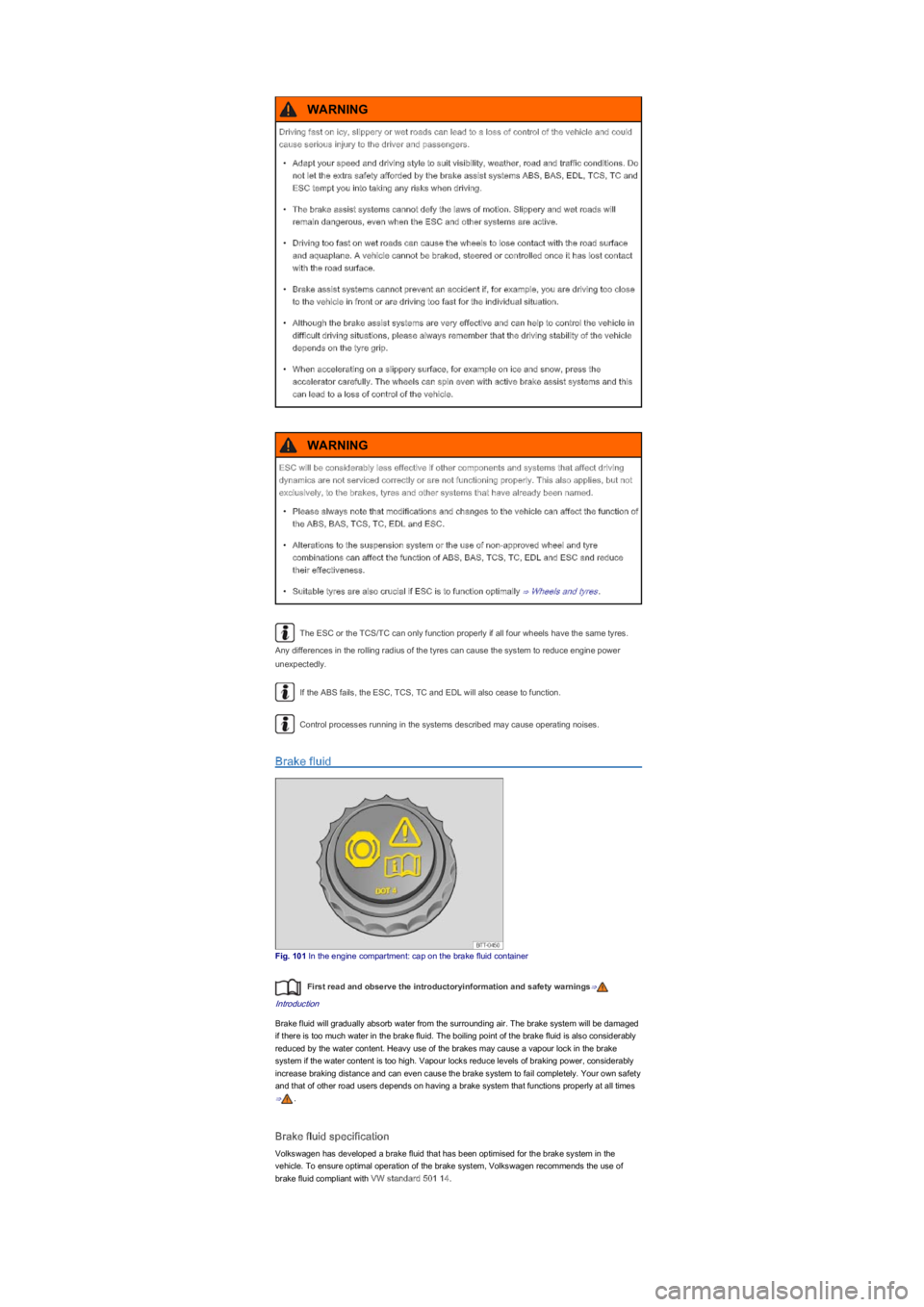
Brake fluid
Fig. 101 In the engine compartment: cap on the brake fluid container
First read and observe the introductoryinformation and safety warnings⇒
Introduction
Brake fluid will gradually absorb water from the surrounding air. The brake system will be damaged
if there is too much water in the brake fluid. The boiling point of the brake fluid is also considerably
reduced by the water content. Heavy use of the brakes may cause a vapour lock in the brake
system if the water content is too high. Vapour locks reduce levels of braking power, considerably
increase braking distance and can even cause the brake system to fail completely. Your own safety
and that of other road users depends on having a brake system that functions properly at all times
⇒.
Brake fluid specification
Volkswagen has developed a brake fluid that has been optimised for the brake system in the
vehicle. To ensure optimal operation of the brake system, Volkswagen recommends the use of
brake fluid compliant with VW standard 501 14.
Driving fast on icy, slippery or wet roads can lead to a loss of control of the vehicle and could
cause serious injury to the driver and passengers.
\f
Page 105 of 211

Before using a particular brake fluid, check that the specifications printed on the container
correspond to the vehicle requirements.
Brake fluid that is compliant with VW standard 501 14 is available from Volkswagen dealerships.
If this brake fluid is not available and it is necessary to use another high-quality brake fluid instead,
brake fluid that is compliant with DIN ISO 4925 CLASS 4 or US standard FMVSS 116 DOT 4 can
be used.
Not all brake fluids that are compliant with DIN ISO 4925 CLASS 4 or US standard FMVSS 116
DOT 4 have the same chemical composition. Some of these brake fluids may contain chemicals
that can damage or destroy brake system components over time.
Volkswagen therefore recommends the use of brake fluid that is compliant with
VW standard 501 14 to ensure sustained optimal operation of the brake system.
Brake fluid that is compliant with VW standard 501 14 fulfils the requirements of DIN ISO 4925
CLASS 4 or US standard FMVSS 116 DOT 4.
Brake fluid level
The brake fluid level must always be between the MIN and MAX marking on the brake fluid
container or above the MIN marking ⇒.
The brake fluid level cannot be checked accurately in all models as engine components may
partially conceal the brake fluid container. If the brake fluid level cannot be read exactly, please
proceed to a qualified workshop.
The brake fluid level drops slightly when the vehicle is being used as the brake pads wear and the
brakes are automatically adjusted.
Changing the brake fluid
The brake fluid must be changed as indicated in the service schedule ⇒BookletService schedule,.
The brake fluid should be changed by a qualified workshop. Volkswagen recommends using a
Volkswagen dealership for this purpose. Only brake fluid that conforms with the required
specification should be used.
Brake fluid can pollute the environment. Any spilt service fluids must be cleaned up and
disposed of properly.
Brake failure or reduced braking effect can be caused by the brake fluid level being too low or
by brake fluid that is too old or unsuitable.
\f
Page 106 of 211
Driving with respect for the environment
Introduction
This chapter contains information on the followingsubjects:
⇒ An economic driving style
⇒ Driving in a fuel-efficient manner
Fuel economy, environmental impact and wear on the engine, brakes and tyres depend largely on
three factors:
\f
Page 112 of 211
Points 1 to 3 must be fulfilled at the same time:
Manual gearboxAutomated manual gearbox
In order to start moving, remove your foot
from the brake pedal, then release the clutch
pedal (clutch engagesyf���D�Q�G���S�U�H�V�V���W�K�H�
accelerator simultaneously. The brake will
gradually be released as the clutch is
engaged.
To start moving, remove your foot from the
brake pedal and press the accelerator
immediately. The brake will gradually be
released as the vehicle pulls away.
The Hill Hold Assist function will be deactivated immediately:
\f
Page 116 of 211

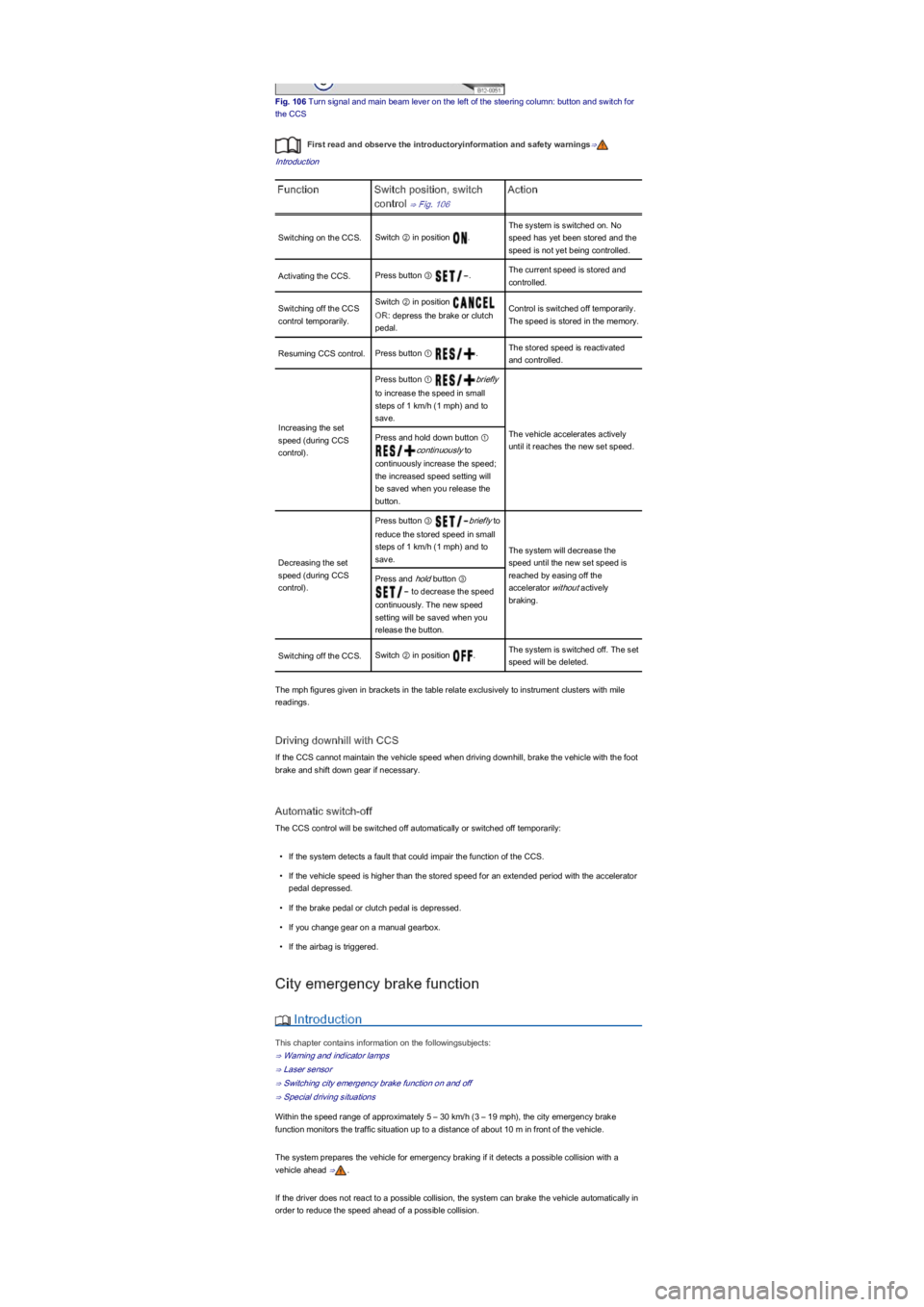
Fig. 106 Turn signal and main beam lever on the left of the steering column: button and switch for
the CCS
First read and observe the introductoryinformation and safety warnings⇒
Introduction
FunctionSwitch position, switch
control ⇒ Fig. 106
Action
Switching on the CCS.Switch ② in position .
The system is switched on. No
speed has yet been stored and the
speed is not yet being controlled.
Activating the CCS.Press button ③ .The current speed is stored and
controlled.
Switching off the CCS
control temporarily.
Switch ② in position
OR: depress the brake or clutch
pedal.
Control is switched off temporarily.
The speed is stored in the memory.
Resuming CCS control.Press button ① .The stored speed is reactivated
and controlled.
Increasing the set
speed (during CCS
controlyf�.
Press button ① briefly
to increase the speed in small
steps of 1 km/h (1 mphyf���D�Q�G���W�R�
save.
The vehicle accelerates actively
until it reaches the new set speed.
Press and hold down button ①
continuously to
continuously increase the speed;
the increased speed setting will
be saved when you release the
button.
Decreasing the set
speed (during CCS
controlyf�.
Press button ③ briefly to
reduce the stored speed in small
steps of 1 km/h (1 mphyf���D�Q�G���W�R�
save.
The system will decrease the
speed until the new set speed is
reached by easing off the
accelerator without actively
braking.
Press and hold button ③
to decrease the speed
continuously. The new speed
setting will be saved when you
release the button.
Switching off the CCS.Switch ② in position .The system is switched off. The set
speed will be deleted.
The mph figures given in brackets in the table relate exclusively to instrument clusters with mile
readings.
Driving downhill with CCS
If the CCS cannot maintain the vehicle speed when driving downhill, brake the vehicle with the foot
brake and shift down gear if necessary.
Automatic switch-off
The CCS control will be switched off automatically or switched off temporarily:
\f
Page 117 of 211
If, in a potential collision scenario, the city emergency brake function detects that the driver is
applying the brakes with insufficient pressure, the system can increase the brake pressure in order
to reduce speed ahead of the collision. Hence the system can help minimise the consequences of
an accident.
Additional information and warnings:
\f
Page 119 of 211
Switching city emergency brake function on and off
Fig. 109 In lower part of centre console: button for the city emergency brake function
First read and observe the introductoryinformation and safety warnings⇒
Introduction
Switching the city emergency brake function on and off
\f
Page 120 of 211

Special driving situations
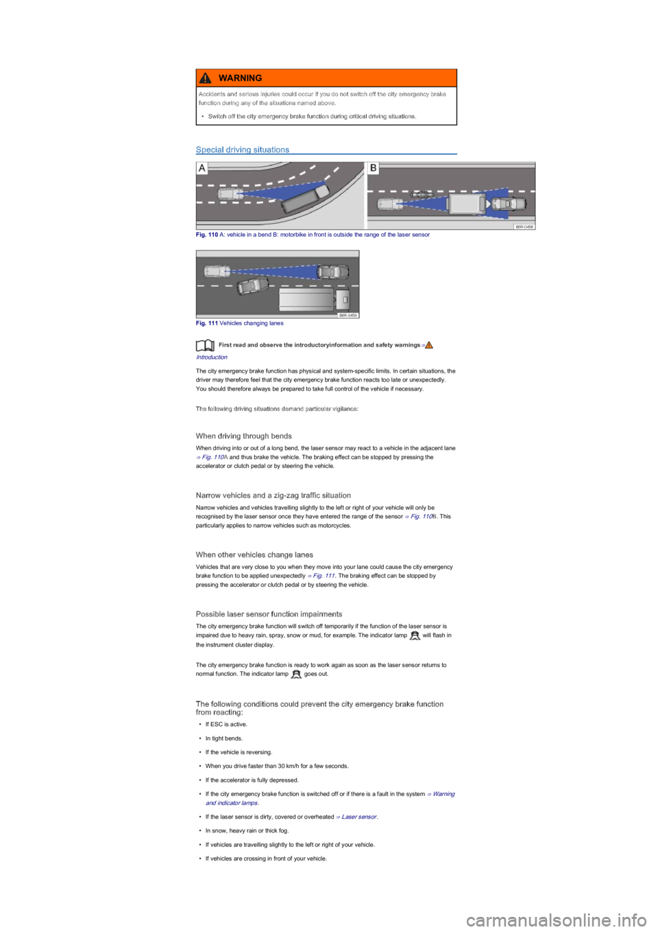
Fig. 110 A: vehicle in a bend B: motorbike in front is outside the range of the laser sensor
Fig. 111 Vehicles changing lanes
First read and observe the introductoryinformation and safety warnings⇒
Introduction
The city emergency brake function has physical and system-specific limits. In certain situations, the
driver may therefore feel that the city emergency brake function reacts too late or unexpectedly.
You should therefore always be prepared to take full control of the vehicle if necessary.
The following driving situations demand particular vigilance:
When driving through bends
When driving into or out of a long bend, the laser sensor may react to a vehicle in the adjacent lane
⇒ Fig. 110A and thus brake the vehicle. The braking effect can be stopped by pressing the
accelerator or clutch pedal or by steering the vehicle.
Narrow vehicles and a zig-zag traffic situation
Narrow vehicles and vehicles travelling slightly to the left or right of your vehicle will only be
recognised by the laser sensor once they have entered the range of the sensor ⇒ Fig. 110B. This
particularly applies to narrow vehicles such as motorcycles.
When other vehicles change lanes
Vehicles that are very close to you when they move into your lane could cause the city emergency
brake function to be applied unexpectedly ⇒ Fig. 111. The braking effect can be stopped by
pressing the accelerator or clutch pedal or by steering the vehicle.
Possible laser sensor function impairments
The city emergency brake function will switch off temporarily if the function of the laser sensor is
impaired due to heavy rain, spray, snow or mud, for example. The indicator lamp will flash in
the instrument cluster display.
The city emergency brake function is ready to work again as soon as the laser sensor returns to
normal function. The indicator lamp goes out.
The following conditions could prevent the city emergency brake function
from reacting:
\f