2015 TATA SAFARI service
[x] Cancel search: servicePage 103 of 161

103
MAINTENANCE
• •• •
•Engine Compartment Engine CompartmentEngine Compartment Engine Compartment
Engine Compartment
• •• •
•Air filter Air filterAir filter Air filter
Air filter
• •• •
•Cooling system Cooling systemCooling system Cooling system
Cooling system
• •• •
•Engine oil & oil filter Engine oil & oil filterEngine oil & oil filter Engine oil & oil filter
Engine oil & oil filter
• •• •
•Changing fuel filter Changing fuel filterChanging fuel filter Changing fuel filter
Changing fuel filter
• •• •
•Changing gear box oil Changing gear box oilChanging gear box oil Changing gear box oil
Changing gear box oil
• •• •
•Changing transfer case oil Changing transfer case oilChanging transfer case oil Changing transfer case oil
Changing transfer case oil
• •• •
•Changing front axle & rear axle oil Changing front axle & rear axle oilChanging front axle & rear axle oil Changing front axle & rear axle oil
Changing front axle & rear axle oil
• •• •
•Head lamp & head lamp focus adjustment Head lamp & head lamp focus adjustmentHead lamp & head lamp focus adjustment Head lamp & head lamp focus adjustment
Head lamp & head lamp focus adjustment
• •• •
•Clutch & brake fluid Clutch & brake fluidClutch & brake fluid Clutch & brake fluid
Clutch & brake fluid
• •• •
•Power steering Power steeringPower steering Power steering
Power steering
• •• •
•L LL L
L
CR CRCR CR
CR
V (if fitt V (if fittV (if fitt V (if fitt
V (if fitt
ed) ed)ed) ed)
ed)
• •• •
•Battery BatteryBattery Battery
Battery
• •• •
•Starting the engine with jump leads Starting the engine with jump leadsStarting the engine with jump leads Starting the engine with jump leads
Starting the engine with jump leads
• •• •
•Wheels & tyres Wheels & tyresWheels & tyres Wheels & tyres
Wheels & tyres
• •• •
•V VV V
V
ehicle c ehicle cehicle c ehicle c
ehicle c
ar arar ar
ar
e ee e
e
• •• •
•Fuses & Relays Fuses & RelaysFuses & Relays Fuses & Relays
Fuses & Relays
• •• •
•Catalytic Converter Catalytic ConverterCatalytic Converter Catalytic Converter
Catalytic Converter
• •• •
•EGR system EGR systemEGR system EGR system
EGR system
• •• •
•T TT T
T
urb urburb urb
urb
o oo o
o
char charchar char
char
ger gerger ger
ger
• •• •
•Air Conditioning Air ConditioningAir Conditioning Air Conditioning
Air Conditioning
• •• •
•Belts tension Belts tensionBelts tension Belts tension
Belts tension
Your TATA SAFARI is designed to give you long trouble free service for
thousands of kilometres/miles. However with proper maintenance
care you can get optimum performance from your vehicle. We have
indicated some of the important maintenance operations to be
carried out on the vehicle. Please read the procedure carefully and
get it attended at Authorised Workshop.
ProCarManuals.com
Page 104 of 161

104
M A I N T E N A N C EENGINE C ENGINE CENGINE C ENGINE C
ENGINE C
OMP OMPOMP OMP
OMP
AR ARAR AR
AR
T TT T
T
MENT (RHD) MENT (RHD)MENT (RHD) MENT (RHD)
MENT (RHD)
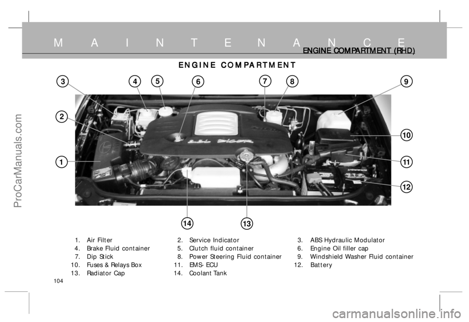
1. Air Filter 2. Service Indicator 3. ABS Hydraulic Modulator
4 . Brake Fluid container 5. Clutch fluid container 6. Engine Oil filler cap
7. Dip Stick 8. Power Steering Fluid container 9. Windshield Washer Fluid container
10. Fuses & Relays Box 11. EMS- ECU 12.Battery
13. Radiator Cap 14. Coolant Tank
ENGINE C ENGINE CENGINE C ENGINE C
ENGINE C
OMP OMPOMP OMP
OMP
AR ARAR AR
AR
T TT T
T
MENT MENTMENT MENT
MENT
38
11
9457
10
14
1
2
6
12
13
ProCarManuals.com
Page 105 of 161

105
AIR FIL AIR FILAIR FIL AIR FIL
AIR FIL
TER TERTER TER
TER
Air Filter Air FilterAir Filter Air Filter
Air Filter
The air filter element should be cleaned as per service schedule .
Replace the air filter element with a new one when the service
indicator shows red band even after cleaning in vehicle operations.
Always use genuine air filter element.
Replacement of Air Filter Element Replacement of Air Filter ElementReplacement of Air Filter Element Replacement of Air Filter Element
Replacement of Air Filter Element
a) Disconnect air filter from hose. Unscrew top cover of the air
filter.
b) Remove the cover of the air filter.
c) Remove the air filter element.
d) Clean the air filter element with pressurised air. Do not tap or
hammer the element on ground.
e) Check element for puncture or pin holes by light source.
f ) If found OK install paper filter element. Fit the cover and tighten air
filter screws at the place.
g) Clean the hose connecting the air filter to turbocharger pipe.
Reset the indicator by pressing the rubber cap, red band will disappear
from Service Indicator.
M A I N T E N A N C E
1. Service Indicator 2. Air filter
ProCarManuals.com
Page 106 of 161

106
Engine Cooling System Engine Cooling SystemEngine Cooling System Engine Cooling System
Engine Cooling System
If engine overheating occurs, there could be a fault in the
cooling system which may be on account of :
1. Less coolant in the cooling system or dirt/scale having
accumulated inside cooling water passages especially
in the radiator core.
2 . Choking of radiator passages due to foreign material or
damages.
3. Defective thermostat.
4. Defective coolant temperature sensor.
5 . Non operation of electrically operated fans (Controlled
by ECU).
6. Coolant leakage.
7. Radiator cap not sealing properly.
8 . A.C. condenser fan not working
9. Excessive refrigerant charging in the A.C. system.
10. No communication between auxiliary tank and radiator.
P PP P
P
r rr r
r
e ee e
e
v vv v
v
en enen en
en
tion of R tion of Rtion of R tion of R
tion of R
ust F ust Fust F ust F
ust F
or oror or
or
ma mama ma
ma
tion tiontion tion
tion
To prevent rust formation in the radiator use premixed
recommended anti-freeze coolant. This is sufficient to
operate the vehicle upto -40
oC.
C CC C
C
OOLING SY OOLING SYOOLING SY OOLING SY
OOLING SY
STEM STEMSTEM STEM
STEMM A I N T E N A N C E
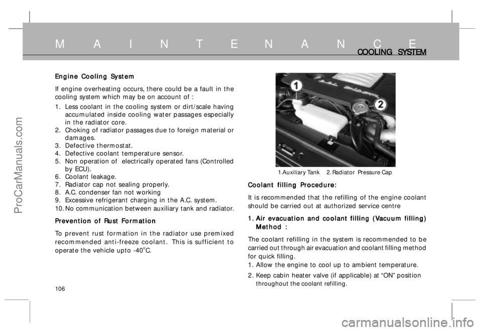
1.Auxiliary Tank 2. Radiator Pressure Cap
Coolant filling Procedure: Coolant filling Procedure:Coolant filling Procedure: Coolant filling Procedure:
Coolant filling Procedure:
It is recommended that the refilling of the engine coolant
should be carried out at authorized service centre
1. 1.1. 1.
1.
A A A A
A
ir e ir eir e ir e
ir e
v vv v
v
acua acuaacua acua
acua
tion and c tion and ction and c tion and c
tion and c
o oo o
o
olan olanolan olan
olan
t filling ( t filling (t filling ( t filling (
t filling (
V VV V
V
acuum filling) acuum filling)acuum filling) acuum filling)
acuum filling)
Method : Method :Method : Method :
Method :
The coolant refilling in the system is recommended to be
carried out through air evacuation and coolant filling method
for quick filling.
1 . Allow the engine to cool up to ambient temperature.
2 . Keep cabin heater valve (if applicable) at “ON” position
throughout the coolant refilling.
ProCarManuals.com
Page 108 of 161

108
Changing of Engine Oil and Oil Filter Changing of Engine Oil and Oil FilterChanging of Engine Oil and Oil Filter Changing of Engine Oil and Oil Filter
Changing of Engine Oil and Oil Filter
Change the oil and oil filter at specified service intervals. (Engine oil and
oil filter may be changed earlier inline with recommendation given for
additional maintenance schedule under severe driving condition)
Changing of oil and oil filter requires access from underneath the vehicle.
Vehicle should be raised on a hydraulic lift of a service station or should
be on a service pit.
1 . Run the engine until it reaches normal operating temperature. Then
shut it off.
2. Remove oil sump guard.
3. Open the bonnet and remove engine oil filler cap. Remove the drain
plug of the oil sump from the bottom of the engine. Drain the oil into
an appropriate container.
4. Remove the oil filter with the help of special wrench. The removed
oil filter should not be reused and hence should be destroyed to
avoid recycling of the same. Used filter and oil should be disposed
in compliance with the current legislation.
5. Ensure cooler is tightened to it’s position.
6. Smear a little fresh engine oil on rubber gasket of new engine oil
filter. Hand tighten the engine oil filter fully and further 3/4 turn with
special tool.
Do not over tighten engine oil filter as this may damage oil filter and
oil may leak out.
7. Before filling in fresh oil in the engine, clean the drain plug..
ENGINE OIL & OIL FIL ENGINE OIL & OIL FILENGINE OIL & OIL FIL ENGINE OIL & OIL FIL
ENGINE OIL & OIL FIL
TER TERTER TER
TER
1. Engine Oil Filling Neck
2. Dip Stick
1. Oil Sump Drain Plug
2. Engine Oil Filter
M A I N T E N A N C E
2 22 2
21 11 1
1
ProCarManuals.com
Page 113 of 161

113
HEAD LAMPS & HEAD LAMP FOCUS ADJUSTMENT HEAD LAMPS & HEAD LAMP FOCUS ADJUSTMENTHEAD LAMPS & HEAD LAMP FOCUS ADJUSTMENT HEAD LAMPS & HEAD LAMP FOCUS ADJUSTMENT
HEAD LAMPS & HEAD LAMP FOCUS ADJUSTMENT
Head Lamps Head LampsHead Lamps Head Lamps
Head Lamps
Your car’s head lamps have H4 type halogen bulbs with twin
filaments, the “High beam” for illuminating the road for long
distances and the “Low beam” for short distance visibility.
The head lamps must be aligned properly for maximum road
illumination and reduced glare for oncoming traffic. The alignment
of head lamp beams should be checked periodically.
A AA A
A
djusting H djusting Hdjusting H djusting H
djusting H
ead Lamp F ead Lamp Fead Lamp F ead Lamp F
ead Lamp F
o oo o
o
cus with the H cus with the Hcus with the H cus with the H
cus with the H
elp of Scr elp of Screlp of Scr elp of Scr
elp of Scr
een: een:een: een:
een:
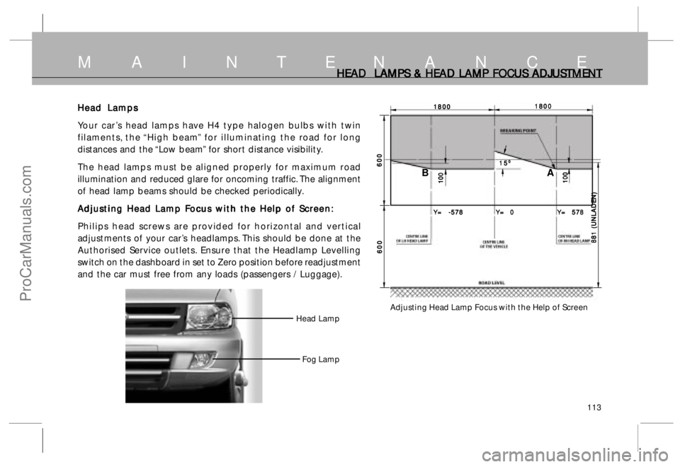
Philips head screws are provided for horizontal and vertical
adjustments of your car’s headlamps. This should be done at the
Authorised Service outlets. Ensure that the Headlamp Levelling
switch on the dashboard in set to Zero position before readjustment
and the car must free from any loads (passengers / Luggage).
M A I N T E N A N C E
Adjusting Head Lamp Focus with the Help of Screen
1800 18001800 1800
18001800 18001800 1800
1800
881 (UNLADEN) 881 (UNLADEN) 881 (UNLADEN) 881 (UNLADEN)
881 (UNLADEN) 100 100 100 100
100 100 100 100 100
100
600 600600 600
600
600 600600 600
600
Y= -578 Y= -578Y= -578 Y= -578
Y= -578
Y= 0 Y= 0Y= 0 Y= 0
Y= 0
Y= 578 Y= 578Y= 578 Y= 578
Y= 578 15 1515 15
15
0 00 0
0
A B
Head Lamp
Fog Lamp
ProCarManuals.com
Page 117 of 161

117
L LL L
L
oad C oad Coad C oad C
oad C
onscious P onscious Ponscious P onscious P
onscious P
r rr r
r
essur essuressur essur
essur
e R e Re R e R
e R
educing educing educing educing
educing
V VV V
V
alv alvalv alv
alv
e (I e (Ie (I e (I
e (I
f fitt f fittf fitt f fitt
f fitt
ed) ed)ed) ed)
ed)
( Not applicable in ABS system) ( Not applicable in ABS system)( Not applicable in ABS system) ( Not applicable in ABS system)
( Not applicable in ABS system)
A load conscious pressure reducing valve eliminates the
possibility of rear wheels from locking and achieves optimum
braking in any load condition of the vehicle.
The valve, is fitted on RH long member connecting it to rear
axle through its link and control spring.
If any, alteration is done in rear suspension, the performance
of this valve will be impaired.
R RR R
R
emot emotemot emot
emot
e B e Be B e B
e B
y-pass y-pass y-pass y-pass
y-pass
V VV V
V
alv alvalv alv
alv
e (I e (Ie (I e (I
e (I
f fitt f fittf fitt f fitt
f fitt
ed) ed)ed) ed)
ed)
(Applicable in ABS system) (Applicable in ABS system)(Applicable in ABS system) (Applicable in ABS system)
(Applicable in ABS system)
The by-pass valve is provided in the rear brake circuit between
tandem master cylinder and ABS unit. The by-pass valve
bypasses the ABS unit in rear only braking (i.e. front brake
failed) condition. The feedback of front line pressure is
provided to the by-pass valve. in case of front brake failure,
the low front line presure being sensed by the by-pass valve
and the 100% brake line pressure from tandem master
cylinder is applied on to the rear brakes without reduction
in pressure.
M A I N T E N A N C EL LL L
L
CR CRCR CR
CR
V (IF FIT V (IF FITV (IF FIT V (IF FIT
V (IF FIT
TED), TED),TED), TED),
TED),
REMO REMO REMO REMO
REMO
TE BY P TE BY PTE BY P TE BY P
TE BY P
ASS ASS ASS ASS
ASS
V VV V
V
AL ALAL AL
AL
VE AND ECU VE AND ECUVE AND ECU VE AND ECU
VE AND ECU
ECU : ECU :ECU : ECU :
ECU :
DICOR engine common rail system consists of ECU, sensors
and actuators. The Electronic control unit (ECU) is a 32 bit
microprocessor which controls the injection parameters as well
as some of the vehicle related outputs. The ECU receives input
from various sensors located on the engine and the vehicle to
decide the injected quantity and injection timing best suited
for the engine to work with maximum efficiency and safety.
ECU is fitted inside the engine compartment.
C CC C
C
AUTIONS AUTIONSAUTIONS AUTIONS
AUTIONS
• •• •
•DO NOT DO NOT DO NOT DO NOT
DO NOT wash engine compartment with high
pressure water
• •• •
•DO NOT DO NOTDO NOT DO NOT
DO NOT tamper with ECU sensors and connectors
• •• •
•DO NOT DO NOTDO NOT DO NOT
DO NOT remove battery connections when the ignition
switch is in ‘ON’ position ( This may damage ECU)
• •• •
•AV AVAV AV
AV
OID OIDOID OID
OID jump start/push start, Use fully charged battery.
• •• •
•DO NO DO NODO NO DO NO
DO NO
T T T T
T run the vehicle if ‘CHECK ENGINE’ lamp on
dashboard is ‘ON.
• •• •
•If any abnormality in performance of engine occurs - like
lack of power- the vehicle to be taken to the
T TT T
T
A AA A
A
T TT T
T
A MO A MOA MO A MO
A MO
T TT T
T
ORS ORSORS ORS
ORS
authorised service outlet.
ProCarManuals.com
Page 122 of 161

122
M A I N T E N A N C EWHEELS & WHEELS & WHEELS & WHEELS &
WHEELS &
T TT T
T
YRES YRESYRES YRES
YRES
REAR JACKING POINT REAR JACKING POINTREAR JACKING POINT REAR JACKING POINT
REAR JACKING POINT
(Below Rear Axle Tube)
FRONT JACKING POINT FRONT JACKING POINTFRONT JACKING POINT FRONT JACKING POINT
FRONT JACKING POINT
(Below Long Member)
CAUTION CAUTIONCAUTION CAUTION
CAUTION
a) Do not lift the vehicle with someone inside.
b) Raise the vehicle only high enough to remove and change
tyre.
c) Do not work under the vehicle when supported by jack
otherwisepersonnel injury may occur.
d ) Do not start or run the vehicle while supported by jack.
NOTICE NOTICENOTICE NOTICE
NOTICE
Check tyre pressure and nut tightness of change wheel at
nearest Service station. Also, get the puncture tyre repaired.
ProCarManuals.com