2015 Seat Ibiza SC Windscreen
[x] Cancel search: WindscreenPage 36 of 248
The essentials
Reading a service notification
W ith the ignition sw
it
ched on, the engine off
and the vehicle at a standstill, the current
service notification can be read:
Press and hold the button 4 for more than 5
sec ond
s
to consult the service message.
When the service date has passed , a minus
sign is displayed in front of the number of kil-
ometres or days.
Vehicles with text messages : the following
message is displayed: Service --- km
(miles) or --- days ago .
The time can also be set via the key and
Set up function button in the Easy Connect
sy s
t
em ›››
page 107.
Resetting service interval display
If the service was not carried out by a SEAT
dealership, the display can be reset as fol-
lows: ● Switch off the ignition, press and hold but-
ton ››
› Fig. 121
4 .
● Switch ignition back on.
● Release THE 4
› ›
›
Fig. 121
button and
press it again for the next 20 seconds. Note
● The serv ic
e message disappears after a few
seconds, when the engine is started or when OK/RESET
is pressed on the windscreen wiper
lev er
, or OK on the multifunction steering
wheel.
● In v
ehicles with the LongLife system in
which the batt
ery has been disconnected for
a long period of time, it is not possible to cal-
culate the date of the next service. Therefore
the service interval display may not be cor-
rect. In this case, bear in mind the maximum
service intervals permitted in the ››› Book-
let Maintenance Programme. Cruise control
Oper atin
g the c
ruise control system
(CCS)* Fig. 41
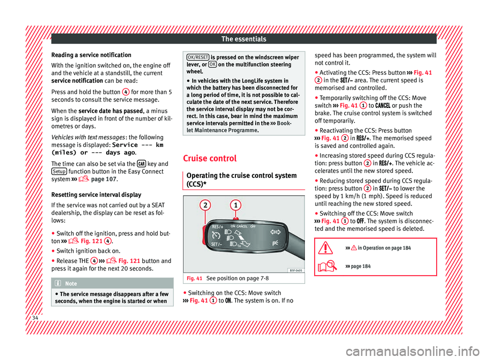
See position on page 7-8 ●
Switching on the CCS: Move switch
› ›
›
Fig. 41 1 to .
The system is on. If no s
peed h as been programmed, the system will
not contr
ol it.
● Activating the CCS: Press button ›››
Fig. 41
2 in the ar
e
a. The current speed is
memorised and controlled.
● Temporarily switching off the CCS: Move
switc
h ››› Fig. 41 1 to
or push the
br ak
e. The cruise control system is switched
off temporarily.
● Reactivating the CCS: Press button
›››
Fig. 41 2 in
. The memorised speed
i s
saved and controlled again.
● Increasing stored speed during CCS regula-
tion: pres
s button 2 in
. The vehicle ac-
c
elerates until the new stored speed.
● Reducing stored speed during CCS regula-
tion: pres
s button 2 in t
o lower the
s peed b
y 1 km/h (1 mph). Speed is reduced
until reaching the new stored speed.
● Switching off the CCS: Move switch
›››
Fig. 41 1 to .
The system is disconnec-
t ed and the memori
sed speed is deleted.
››› in Operation on page 184
››› page 184 34
Page 39 of 248
The essentials
Fault in the battery.›››
page
209
Driving light totally or partially
faulty.›››
page
83
Fault in the cornering light sys-
tem.››› page
123
Diesel particulate filter blocked›››
page
101
Level of windscreen washer fluid
too low.›››
page
209
Flashing: Fault in the oil level de-
tection. Control manually.›››
page
204
Ignition: Insufficient engine oil.
Fault in the gearbox.›››
page
164
Immobiliser active.›››
page
107
Service interval display›››
page
33
Mobile telephone is connected
via Bluetooth to the original tele-
phone device.›››
Book-
let Radio
or
››› Book-
let Navi-
gation
system
Mobile telephone battery charge
meter. Available only for devices
pre-installed in factory.
Freezing warning. The outside
temperature is lower than +4°C
(+39°F).›››
page
27
Start-Stop system activated.›››
page
173
Start-Stop system unavailable.
Low consumption driving status›››
page
27 On the instrument panel
Fig. 44
See position on page 7-8
Front passenger front airbag is
disabled (
).
››› page
66
››› in Warning symbols on page 101
›››
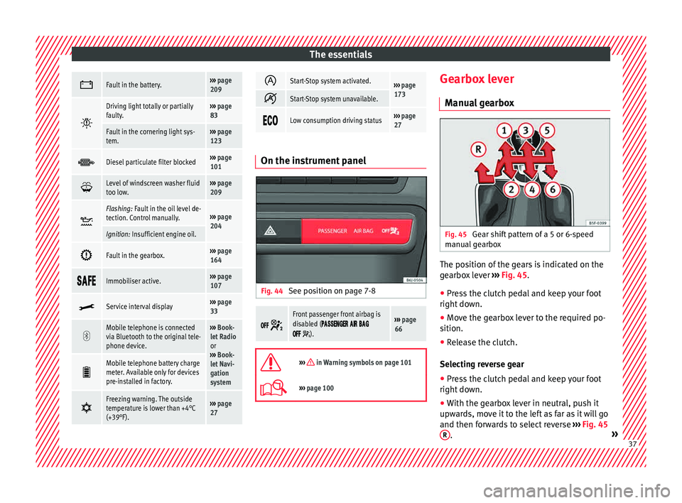
page 100 Gearbox lever
M anua
l
gearbox Fig. 45
Gear shift pattern of a 5 or 6-speed
m anual
g
earbox The position of the gears is indicated on the
g
e
arbo
x lever ››› Fig. 45.
● Press the clutch pedal and keep your foot
right down.
● Mo
ve the gearbox lever to the required po-
sition.
● Rel
ease the clutch.
Selecting r
everse gear
● Press the clutch pedal and keep your foot
right down.
● W
ith the gearbox lever in neutral, push it
upwar
ds, move it to the left as far as it will go
and then forwards to select reverse ››› Fig. 45
R .
» 37
Page 41 of 248

The essentials
Air conditioning Ho w doe
s
Climatronic* work? Fig. 48
See position on page 7-8 Buttons/controls
Interior t
emper
ature setting
Display Selected interior temperature
Degrees Centigrade or Fahrenheit
Automatic air conditioning mode
Defrost or demist windscreen
Air flow direction
Air recirculation
Air conditioning on/off
Selected blower speed
1 2
3
4
5
6
7
8
9 Buttons/controls
Set b
lo
wer speed
Interior temperature sensors
Defrost or demist windscreen
Automatic mode
Air distribution to windows
Air distribution to upper body
Air distribution to footwells
Air recirculation
Air conditioning on/off
10 11
12
13
14
15
16
17
18 ››› in General notes on page 144
›››
page 150 39
Page 42 of 248
The essentials
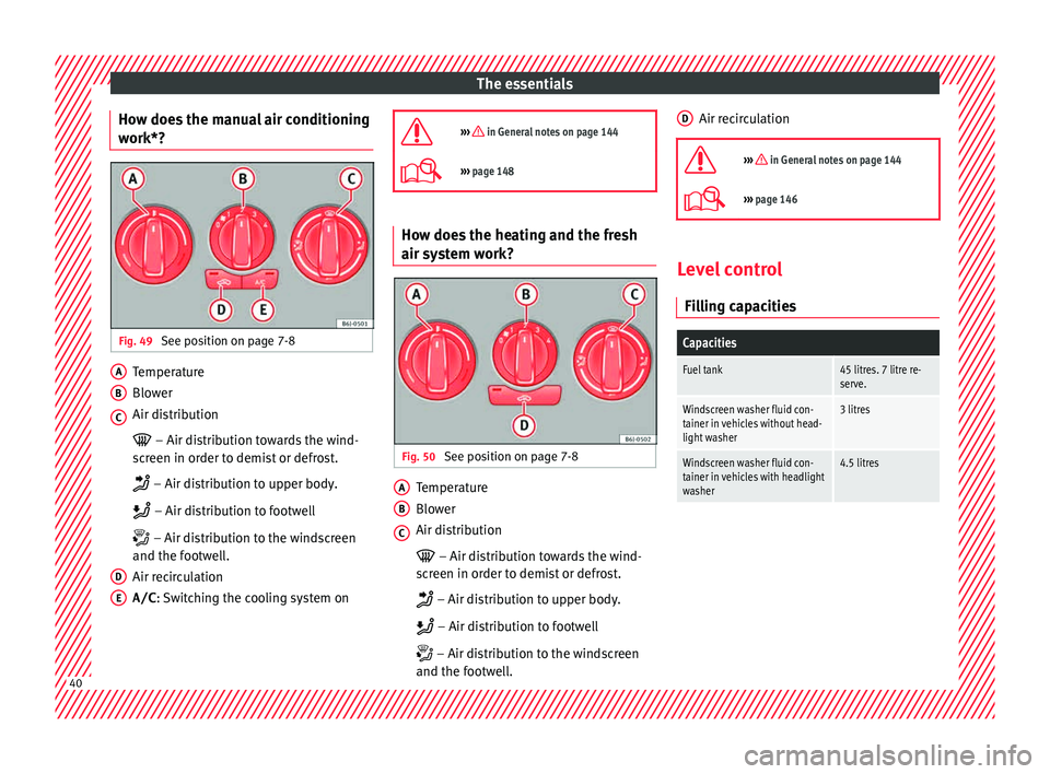
How does the manual air conditioning
w ork*? Fig. 49
See position on page 7-8 Temperature
Blo
w
er
Air di
stribution
– Air distribution towards the wind-
screen in order to demist or defrost.
– Air distribution to upper body.
– Air distribution to footwell
– Air distribution to the windscreen
and the footwell.
Air recirculation
A/C : Switching the cooling system on
A B
C
D
E
››› in General notes on page 144
›››
page 148 How does the heating and the fresh
air sy
s
t
em work? Fig. 50
See position on page 7-8 Temperature
Blo
w
er
Air di
stribution
– Air distribution towards the wind-
screen in order to demist or defrost.
– Air distribution to upper body.
– Air distribution to footwell
– Air distribution to the windscreen
and the footwell.
A B
C Air recirculation
››› in General notes on page 144
››› page 146 Level control
Fi l
lin
g capacities
Capacities
Fuel tank45 litres. 7 litre re-
serve.
Windscreen washer fluid con-
tainer in vehicles without head-
light washer3 litres
Windscreen washer fluid con-
tainer in vehicles with headlight
washer4.5 litres D
40
Page 45 of 248
The essentials
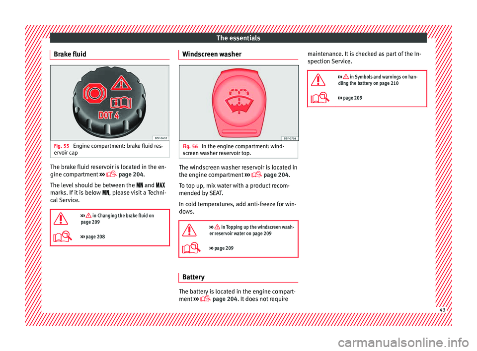
Brake fluid Fig. 55
Engine compartment: brake fluid res-
er v
oir c
ap The brake fluid reservoir is located in the en-
gine c
omp
ar
tment ›››
page 204.
The level should be between the and
marks. If it is below , please visit a Techni-
cal Service.
››› in Changing the brake fluid on
page 209
››› page 208 Windscreen washer
Fig. 56
In the engine compartment: wind-
s c
r
een washer reservoir top. The windscreen washer reservoir is located in
the en
gine c
omp
artment ›››
page 204.
To top up, mix water with a product recom-
mended by SEAT.
In cold temperatures, add anti-freeze for win-
dows.
››› in Topping up the windscreen wash-
er reservoir water on page 209
››› page 209 Battery
The battery is located in the engine compart-
ment
›
›
› page 204. It does not require maintenance. It is checked as part of the In-
spection Ser
vice.
››› in Symbols and warnings on han-
dling the battery on page 210
››› page 209 43
Page 53 of 248
The essentials
Emergency towing of the vehi-
c l
e
T
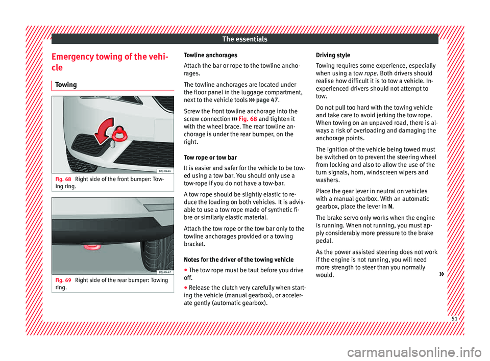
owing Fig. 68
Right side of the front bumper: Tow-
in g rin
g. Fig. 69
Right side of the rear bumper: Towing
rin g. Towline anchorages
Att
ac
h the b
ar or rope to the towline ancho-
rages.
The towline anchorages are located under
the floor panel in the luggage compartment,
next to the vehicle tools ››› page 47.
Screw the front towline anchorage into the
screw connection ››› Fig. 68 and tighten it
with the wheel brace. The rear towline an-
chorage is under the rear bumper, on the
right.
Tow rope or tow bar
It is easier and safer for the vehicle to be tow-
ed using a tow bar. You should only use a
tow-rope if you do not have a tow-bar.
A tow rope should be slightly elastic to re-
duce the loading on both vehicles. It is advis-
able to use a tow rope made of synthetic fi-
bre or similarly elastic material.
Attach the tow rope or the tow bar only to the
towline anchorages provided or a towing
bracket.
Notes for the driver of the towing vehicle
● The tow rope must be taut before you drive
off.
● Rel
ease the clutch very carefully when start-
ing the v
ehicle (manual gearbox), or acceler-
ate gently (automatic gearbox). Driving style
Tow
ing requires some experience, especially
when using a tow rope. Both drivers should
realise how difficult it is to tow a vehicle. In-
experienced drivers should not attempt to
tow.
Do not pull too hard with the towing vehicle
and take care to avoid jerking the tow rope.
When towing on an unpaved road, there is al-
ways a risk of overloading and damaging the
anchorage points.
The ignition of the vehicle being towed must
be switched on to prevent the steering wheel
from locking and also to allow the use of the
turn signals, horn, windscreen wipers and
washers.
Place the gear lever in neutral on vehicles
with a manual gearbox. With an automatic
gearbox, place the lever in N.
The brake servo only works when the engine
is running. When not running, you must ap-
ply considerably more pressure to the brake
pedal.
As the power assisted steering does not work
if the engine is not running, you will need
more strength to steer than you normally
would. » 51
Page 56 of 248

The essentials
Note
The vehicles must not touch each other, oth-
erw i
se electricity could flow as soon as the
positive terminals are connected. Changing the windscreen wiper
bl
a
des
Changing the wiper blades Fig. 72
Wipers in service position Fig. 73
Changing the windscreen wiper
bl a
de. To change the blades it is necessary to move
the w
iper
s
from the rest position into the
service position.
Do not change the windscreen wipers when
out of the service position, as it could cause
paint to flake off the bonnet due to friction
with the windscreen wiper arm.
Service position (for changing wiper blades)
● Ensure that the wiper blades are not frozen.
● Turn the ignition on and off and then (with-
in appro
ximately 9 seconds) push the wind-
screen wiper lever down (short wipe). The
windscreen wipers will move to the service
position ››› Fig. 72.
Removing the wiper blade
● Lift the windscreen wiper arm.
● Press the securing tab down 1
› ›
› Fig. 73
.●
Extract the w
iper blade from the wiper arm.
Fitting the wiper blade ● Insert the wiper blade onto the windscreen
wiper arm unti
l it clicks into place.
● Place the windscreen wiper arms to their in-
itial po
sition.
››› in Changing the windscreen and
rear window wiper blades on page 79
››› page 78 Changing the rear window wiper blade
Fig. 74
Removing and fitting the rear window
w iper b
l
ade. Removing the wiper blade
● Lift the wiper arm away from the glass 54
Page 57 of 248
The essentials
● Slide the b l
a
de adapter in the direction of
the arrow and remove the blade ››› Fig. 74 A.
Fitting the wiper blade ● With one hand, hold the top end of the wip-
er arm.
● Place the blade as shown in ›››
Fig. 74 B
and slide the adapter along until it engages.
››› in Changing the windscreen and
rear window wiper blades on page 79
››› page 78 55