2015 Seat Altea XL wheel
[x] Cancel search: wheelPage 82 of 236
Operation
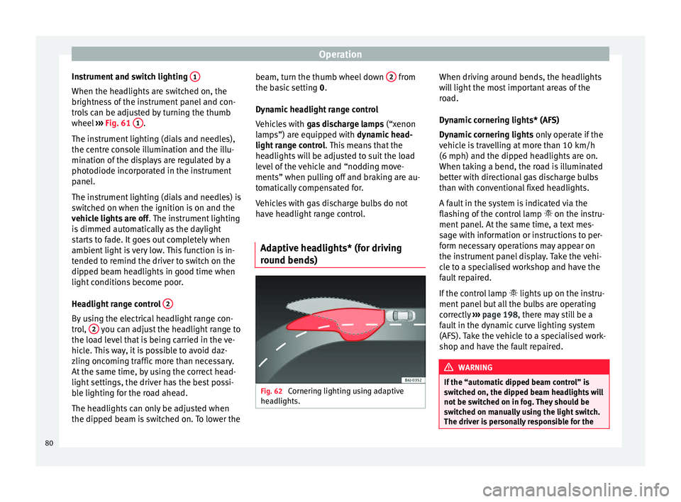
Instrument and switch lighting 1When the headlights are switched on, the
brightness of the instrument panel and con-
trols can be adjusted by turning the thumb
wheel
››› Fig. 61 1 .
The instrument lighting (dials and needles),
the centre console illumination and the illu-
mination of the displays are regulated by a
photodiode incorporated in the instrument
panel.
The instrument lighting (dials and needles) is
switched on when the ignition is on and the
vehicle lights are off . The instrument lighting
is dimmed automatically as the daylight
starts to fade. It goes out completely when
ambient light is very low. This function is in-
tended to remind the driver to switch on the
dipped beam headlights in good time when
light conditions become poor.
Headlight range control 2By using the electrical headlight range con-
trol,
2 you can adjust the headlight range to
the load level that is being carried in the ve-
hicle. This way, it is possible to avoid daz-
zling oncoming traffic more than necessary.
At the same time, by using the correct head-
light settings, the driver has the best possi-
ble lighting for the road ahead.
The headlights can only be adjusted when
the dipped beam is switched on. To lower the beam, turn the thumb wheel down
2 from
the basic setting 0.
D y
namic headlight range control
Vehicles with gas discharge lamps (“xenon
lamps”) are equipped with
dynamic head-
light range control . This means that the
headlights will be adjusted to suit the load
level of the vehicle and “nodding move-
ments” when pulling off and braking are au-
tomatically compensated for.
Vehicles with gas discharge bulbs do not
have headlight range control.
Adaptive headlights* (for driving
round bends) Fig. 62
Cornering lighting using adaptive
headlights. When driving around bends, the headlights
will light the most important areas of the
road.
Dynamic cornering lights* (AFS)
Dynamic cornering lights
only operate if the
vehicle is travelling at more than 10 km/h
(6 mph) and the dipped headlights are on.
When taking a bend, the road is illuminated
better with directional gas discharge bulbs
than with conventional fixed headlights.
A fault in the system is indicated via the
flashing of the control lamp on the instru-
ment panel. At the same time, a text mes-
sage with information or instructions to per-
form necessary operations may appear on
the instrument panel display. Take the vehi-
cle to a specialised workshop and have the
fault repaired.
If the control lamp lights up on the instru-
ment panel but all the bulbs are operating
correctly ››› page 198 , there may still be a
f au
lt in the dynamic curve lighting system
(AFS). Take the vehicle to a specialised work-
shop and have the fault repaired. WARNING
If the “automatic dipped beam control” is
switched on, the dipped beam headlights will
not be switched on in fog. They should be
switched on manually using the light switch.
The driver is personally responsible for the 80
Page 86 of 236
Operation
Rear window sun blind* – Pull out the visor and hook it onto the
hooks at the top of the door frame
››› Fig. 68 .
W ind
screen wiper and rear
window wiper systems
Windscreen wipers Fig. 69
Windscreen wiper lever. Fig. 70
Rain sensor on the windscreen seen
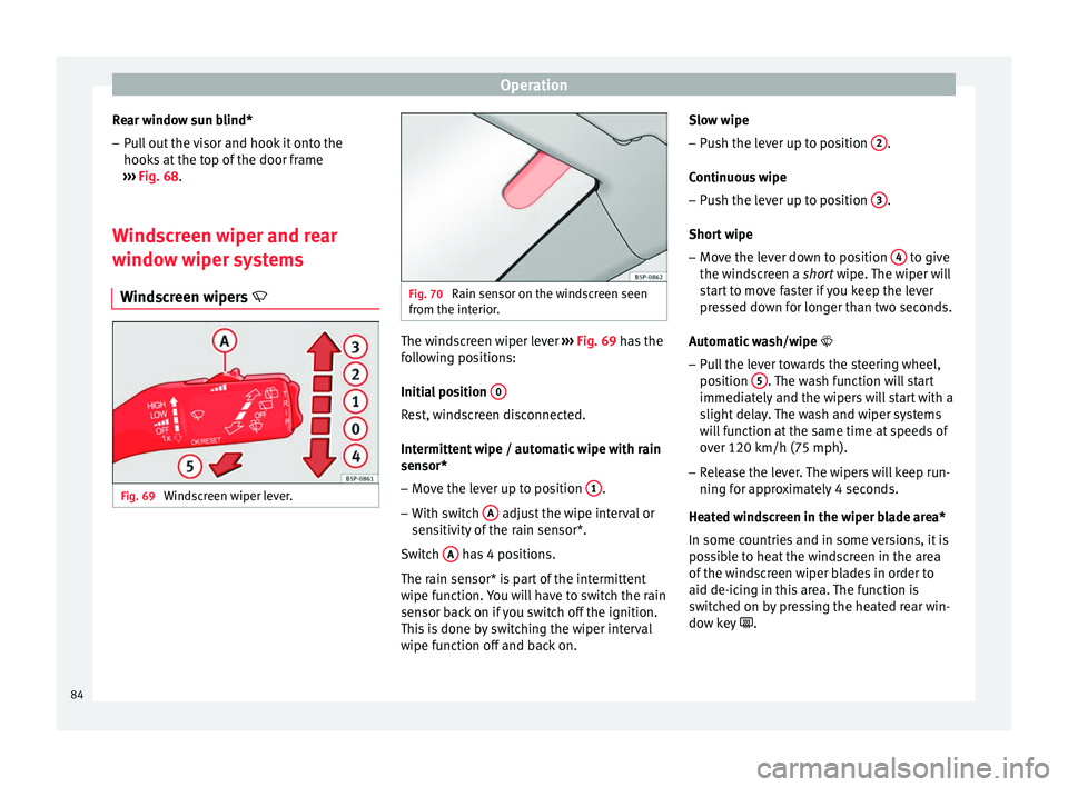
from the interior. The windscreen wiper lever
››› Fig. 69 has the
f o
llowing positions:
Initial position 0 Rest, windscreen disconnected.
Intermittent wipe / automatic wipe with rain
sensor*
– Move the lever up to position 1 .
– With switch A adjust the wipe interval or
sensitivity of the rain sensor*.
Switch A has 4 positions.
The rain sensor* is part of the intermittent
wipe function. You will have to switch the rain
sensor back on if you switch off the ignition.
This is done by switching the wiper interval
wipe function off and back on. Slow wipe
–
Push the lever up to position 2 .
Continuous wipe – Push the lever up to position 3 .
Short wipe – Move the lever down to position 4 to give
the windscreen a short wipe. The wiper will
s t
art to move faster if you keep the lever
pressed down for longer than two seconds.
Automatic wash/wipe
– Pull the lever towards the steering wheel,
position 5 . The wash function will start
immediately and the wipers will start with a
slight delay. The wash and wiper systems
will function at the same time at speeds of
over 120 km/h (75 mph).
– Release the lever. The wipers will keep run-
ning for approximately 4 seconds.
Heated windscreen in the wiper blade area*
In some countries and in some versions, it is
possible to heat the windscreen in the area
of the windscreen wiper blades in order to
aid de-icing in this area. The function is
switched on by pressing the heated rear win-
dow key .
84
Page 87 of 236

Lights and visibility
WARNING
● Worn and dirty wiper blades reduce visibili-
ty and safety levels while driving.
● In cold conditions, you should not use the
wash/wipe system unless you have warmed
the windscreen with the heating and ventila-
tion system. The windscreen washer fluid
could otherwise freeze on the windscreen and
obscure your view of the road.
● The rain sensor may not detect enough rain
to switch on the wipers. If necessary, switch
on the wipers manually when water on the
windscreen impedes visibility.
● Always note the corresponding warnings
››› page 194. CAUTION
In icy conditions, always check that the wiper
blades are not frozen to the glass before us-
ing the wipers for the first time. If you switch
on the windscreen wipers when the wiper
blades are frozen to the windscreen, you
could damage both the wiper blades and the
wiper motor. Note
● The windscreen wipers will only work when
the ignition is switched on.
● In certain versions of vehicles with alarms,
the windscreen wiper will only work when the
ignition is on and the bonnet closed. ●
When in use, the wipers do not go as far as
the rest position. When the lever is moved to
position 0, they are totally hidden.
● If the vehicle stops when wiper speed 2 ›››
Fig. 69 or 3 is selected, the next speed
down will be selected automatically. The set
speed will be resumed when the vehicle pulls
away.
● The windscreen will be wiped again after
approximately five seconds once the “auto-
matic wash/wipe system” has been activa-
ted, provided the vehicle is moving (drip func-
tion). If you activate the wipers less than 3
seconds after the drip function, a new wash
sequence will begin without performing the
last wipe. For the “drip” function to work
again, you have to turn the ignition off and
then on again.
● When the “interval wipe function” is on,
the intervals are directly proportional to the
speed. This way, the higher the vehicle speed
the shorter the intervals.
● The wiper will try to wipe away any obsta-
cles that are on the windscreen. The wiper
will stop moving if the obstacle continues to
block its path. Remove the obstacle and
switch the wiper back on again.
● Before removing any objects that may be
trapped in the side areas of the windscreen,
always move the wiper arms to the service
position (horizontal).
● The heat output of the heated jets is con-
trolled automatically when the ignition is
switched on, depending upon the outside
temperature. ●
Do not put stickers on the windscreen in
front of the rain sensor*. This may cause sen-
sor disruption or faults. Rear window wiper
Fig. 71
Windscreen wiper lever: rear window
wiper. Switching on the interval wipe
– Press the lever forward to position 6 ›››
Fig. 71 . The wiper will wipe the window
ap pr
oximately every 6 seconds.
Switching off the interval wipe function
– Pull the lever back from position 6 toward
the steering wheel. The wiper will continue
to function for a short period if you switch
off whilst the wipers are in motion. »
85
Technical specifications
Advice
Operation
Safety
Page 88 of 236
Operation
Switching on automatic wipe – Press the lever fully forwards to position 7›››
Fig. 71 . The rear wash function will start
immedi at
ely and the wiper will start a few
seconds later. The rear window wash sys-
tem will function as long as you hold the
lever in this position.
– Release the lever. The wiper then wipes for
approximately 4 seconds, and then in inter-
vals again.
– Release the lever. The washer system stops
and the wipers function. WARNING
● Worn and dirty wiper blades reduce visibili-
ty and safety levels while driving.
● Always note the corresponding warnings
on ››› page 194. CAUTION
In icy conditions, always check that the wiper
blade is not frozen to the glass before using
the wiper for the first time. If you switch on
the wiper when the wiper blade is frozen to
the glass, this could damage both the wiper
blade and the wiper motor. Note
● The windscreen wiper will only function
when the ignition is switched on and the rear
lid is closed. ●
In reverse gear, with the windscreen wipers
switched on, the rear windscreen wiper will
make one wipe. Headlight washer*
The headlight washers clean the headlight
lenses.
The headlight washers are activated auto-
matically when the windscreen washer is
used and the window wiper lever is pulled to-
wards the steering wheel for at least 1.5 sec-
onds – provided the dipped beam headlights
or main beams are switched on. Clean off
stubborn dirt (insects, etc.) from the head-
lights at regular intervals, for instance, when
filling the fuel tank.
Note
● To ensure that the headlight washers work
properly in winter, keep the nozzle holders in
the bumper free of snow and remove any ice
with a de-icer spray.
● To remove water, the windscreen wipers
will be activated from time to time, the head-
light washers will be activated every three cy-
cles. Rear vision mirrors
Interior rear vision mirror It is dangerous to drive if you cannot see
clearly through the rear window.
Manual anti-dazzle function for interior rear
vision mirror
In the basic mirror position, the lever at the
bottom edge of the rear vision mirror should
be at the front. Pull the lever to the back to
select the anti-dazzle function.
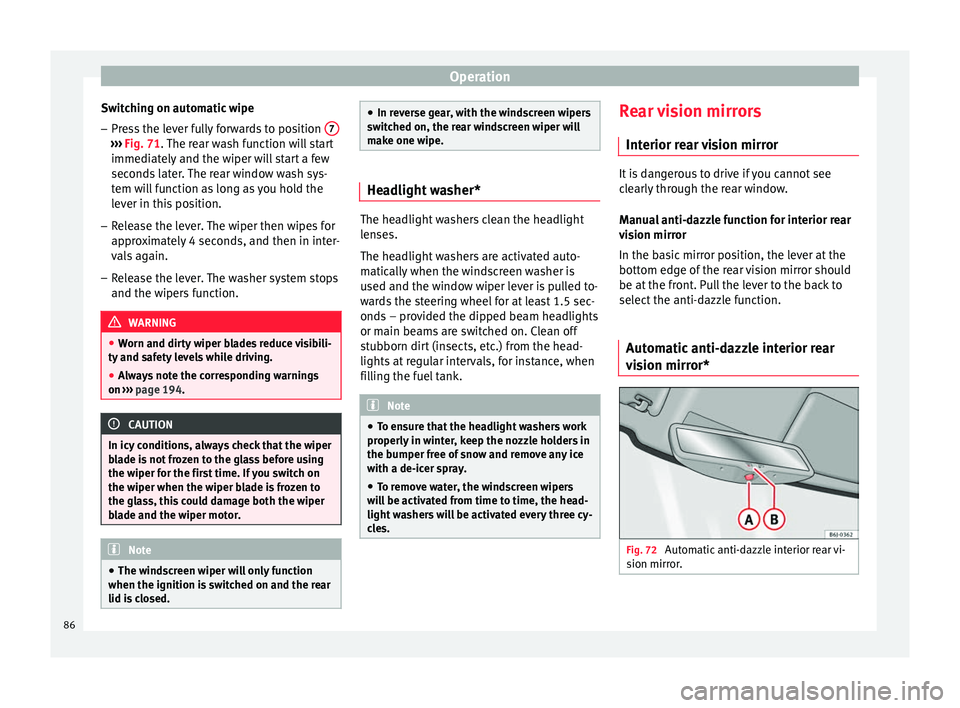
Automatic anti-dazzle interior rear
vision mirror* Fig. 72
Automatic anti-dazzle interior rear vi-
sion mirror. 86
Page 91 of 236

Seats and head restraints
●
Never transport more than the permitted
amount of people in your vehicle.
● Every vehicle occupant must properly fas-
ten and wear the seat belt belonging to his or
her seat. Children must be protected with an
appropriate child restraint system ››› page 24,
Transporting children safety.
● The front seats and all head restraints must
always be adjusted to body size and the seat
belt must always be properly adjusted to pro-
vide you and your passengers with optimum
protection.
● Always keep your feet on the footwell when
the vehicle is moving; never rest them on the
dash panel, out of the window or on the seat.
This is also applied to passengers. An incor-
rect sitting position exposes you to an in-
creased risk of injury in case of a sudden
braking or an accident. If the airbag is trig-
gered, you could sustain severe injuries due
to an incorrect sitting position.
● It is important for the driver and front pas-
senger to keep a distance of at least 25 cm
from the steering wheel and dash panel. Fail-
ure to respect the minimum distance means
that the airbag will not protect you. Risk of
fatal injury. The distance between the driver
and the steering wheel or between the front
passenger and the dash panel should always
be as great as possible.
● Adjust the driver or front passenger seat
only when the vehicle is stationary. This also
applies to the forwards/backwards adjust-
ment of the rear seats. Otherwise, your seat
could move unexpectedly while the vehicle is moving. This could increase the risk of an ac-
cident and therefore, injury. In addition,
while adjusting your seat, you will assume an
incorrect sitting position. Risk of fatal acci-
dents.
●
Special guidelines apply to installing a
child seat on the front passenger seat. When
installing a child seat, please observe the
warnings described in ››› page 24, Transport-
ing children safety. Adjustment of the front seats
Fig. 74
Front left seat controls The control elements in
››› Fig. 74 are mir-
r or
ed for the front right-hand seat.
1 Adjusting the seat forwards and
backwards
– Pull up the grip and move the seat forwards
or backwards. –
Then release the grip 1 and move the seat
further until the catch engages.
2 Adjusting the seat height*
– Pull the lever up or push down (several
times if necessary) from its home position.
This adjusts the seat height in stages.
3 Adjusting the backrest angle
– Take your weight off the backrest and turn
the hand wheel.
4 Adjusting the lumbar support*
– Take your weight off the backrest and turn
the hand wheel to adjust the lumbar sup-
port.
As you make the adjustments, the curvature
of the cushioned area of the lumbar region
becomes more or less acute. In this way, it
adapts to the natural curvature of the spine. WARNING
● Never adjust the driver or front passenger
seat while the vehicle is in motion. While ad-
justing your seat, you will assume an incor-
rect sitting position. Risk of fatal accidents.
Adjust the driver or front passenger seat only
when the vehicle is stationary.
● To reduce the risk of injury to the driver and
front passenger in case of a sudden braking
or an accident, never drive with the backrest
tilted towards the rear. The maximum » 89
Technical specifications
Advice
Operation
Safety
Page 93 of 236

Seats and head restraints
Angle adjustment (front seats) – Press the head restraint forward or back to
the required position.
Removing the head restraint – Push the head restraint up as far as it will
go.
– Press the button ››› Fig. 76 (arrow).
– Pull head restraint out of fitting without re-
leasing the button.
Fitting the head restraint
– Insert the head restraint into the guides on
the backrest.
– Push head restraint down.
– Adjust the head restraint to suit body size
››› page 10 and
›
›› page 9. WARNING
● Never drive if the head restraints have been
removed. Risk of injury.
● Never drive if the head restraints are in an
unsuitable position, there is a risk of serious
injury.
● After refitting the head restraint, you must
always adjust it properly for height to achieve
optimal protection.
● Please observe the safety warnings in
››› page 90, Correct adjustment of head re-
straints. Seat functions
Heated seats* Fig. 77
Thumb wheel for front seat heating. Fig. 78
Front seat heating with Climatronic. The front seat cushions and backrests can be
heated electrically.Front seat heating for vehicles without
Climatronic
– Turn the appropriate thumb wheel
››› Fig. 77 to switch on the seat heating. The
se at
heating is switched off in the 0 posi-
tion.
Front seat heating for vehicles with
Climatronic – Press the button to switch on seat heating.
– Press once to set seat heating at maximum
level (level 3).
– Press twice to set seat heating at medium
level (level 2).
– Press three times to set seat heating at
minimum level (level 1).
– When the button is pressed four times, the
heating goes off and the LED goes out (lev-
el 0).
The seat heating only works when the igni-
tion is switched on. The left thumb wheel
controls the left seat and the right thumb
wheel the right seat. CAUTION
To avoid damaging the heating elements,
please do not kneel on the seat or apply
sharp pressure at a single point to the seat
cushion and backrest. 91
Technical specifications
Advice
Operation
Safety
Page 98 of 236
Operation
● in the side trims of the luggage compart-
ment,
● in the spare wheel recess in the luggage
compartment (only on vehicles with an op-
tional anti-puncture kit*.
The clothes hooks are located on the rear
roof handles. WARNING
● Do not store loose objects on the dash pan-
el. These objects could be flung through the
passenger compartment when the vehicle is
moving (e.g. while accelerating, braking or
cornering) and distract the driver.
● Ensure that no objects can fall from the
centre console or other storage compart-
ments into the driver footwell while the vehi-
cle is moving. In the event of a sudden brak-
ing manoeuvre, you will not be able to use
the brake, clutch or accelerator. Risk of acci-
dent.
● Clothing hung on the coat hooks must not
restrict the driver's view. Risk of accident.
The coat hooks are intended only for use with
light articles of clothing. Do not leave any
hard, sharp or heavy objects in hanging arti-
cles of clothing. During sudden braking ma-
noeuvres or accidents, especially those in-
volving airbag deployment, these objects
could injure the vehicle occupants. Multi-purpose mobile storage
compartment*
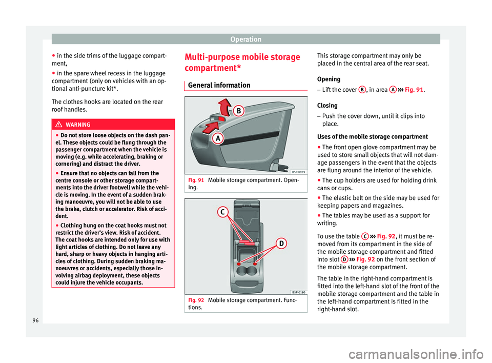
General information Fig. 91
Mobile storage compartment. Open-
ing. Fig. 92
Mobile storage compartment. Func-
tions. This storage compartment may only be
placed in the central area of the rear seat.
Opening
– Lift the cover B , in area
A
››› Fig. 91 .
C lo
sing
– Push the cover down, until it clips into
place.
Uses of the mobile storage compartment
● The front open glove compartment may be
used to store small objects that will not dam-
age passengers in the event that the objects
are flung around the interior of the vehicle.
● The cup holders are used for holding drink
cans or cups.
● The elastic belt on the side may be used for
keeping papers and magazines.
● The tables may be used as a support for
writing.
To use the table C
››› Fig. 92 , it must be re-
mo v
ed from its compartment in the side of
the mobile storage compartment and fitted
into slot D
››› Fig. 92 on the front section of
the mo b
ile storage compartment.
The table in the right-hand compartment is
fitted into the left-hand slot of the front of the
mobile storage compartment and the table in
the left-hand compartment is fitted in the
right-hand slot.
96
Page 106 of 236
Operation
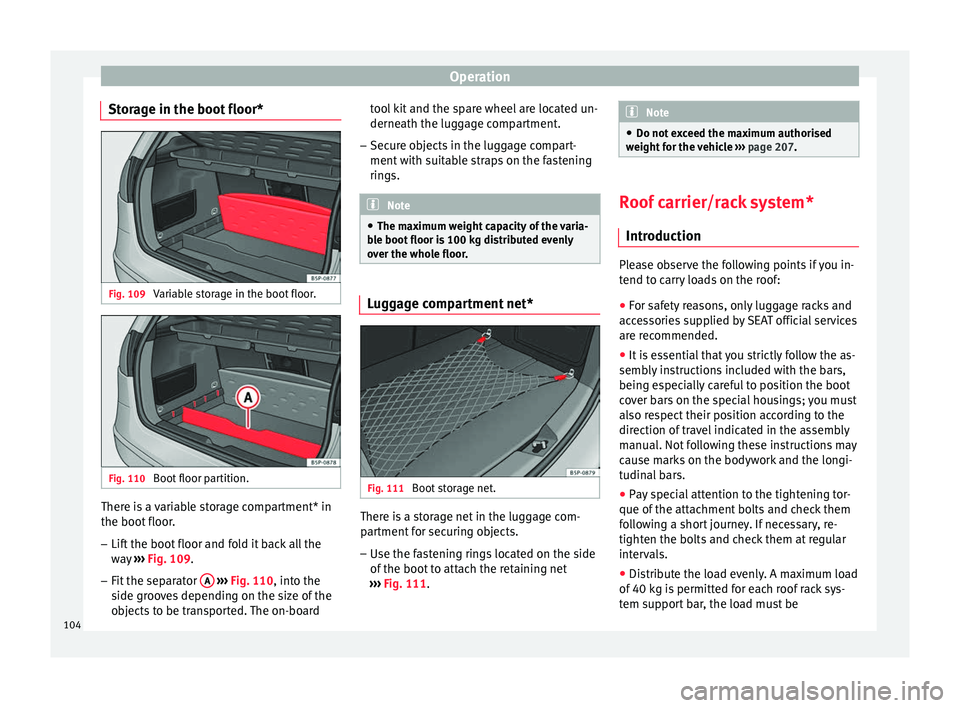
Storage in the boot floor* Fig. 109
Variable storage in the boot floor. Fig. 110
Boot floor partition. There is a variable storage compartment* in
the boot floor.
–
Lift the boot floor and fold it back all the
way ››› Fig. 109 .
– Fit the sep
arator A
››› Fig. 110
, into the
s ide gr
ooves depending on the size of the
objects to be transported. The on-board tool kit and the spare wheel are located un-
derneath the luggage compartment.
– Secure objects in the luggage compart-
ment with suitable straps on the fastening
rings. Note
● The maximum weight capacity of the varia-
ble boot floor is 100 kg distributed evenly
over the whole floor. Luggage compartment net*
Fig. 111
Boot storage net. There is a storage net in the luggage com-
partment for securing objects.
– Use the fastening rings located on the side
of the boot to attach the retaining net
››› Fig. 111 . Note
● Do not exceed the maximum authorised
weight for the vehicle ››› page 207. Roof carrier/rack system*
Introduction Please observe the following points if you in-
tend to carry loads on the roof:
● For safety reasons, only luggage racks and
accessories supplied by SEAT official services
are recommended.
● It is essential that you strictly follow the as-
sembly instructions included with the bars,
being especially careful to position the boot
cover bars on the special housings; you must
also respect their position according to the
direction of travel indicated in the assembly
manual. Not following these instructions may
cause marks on the bodywork and the longi-
tudinal bars.
● Pay special attention to the tightening tor-
que of the attachment bolts and check them
following a short journey. If necessary, re-
tighten the bolts and check them at regular
intervals.
● Distribute the load evenly. A maximum load
of 40 kg is permitted for each roof rack sys-
tem support bar, the load must be
104