Page 105 of 236

2.23
TYRE PRESSURE MONITORING SYSTEM (4/4)
CD
EF
5
5
6
Each of the sensors incorporated in the valves 5 is dedicated to a single
wheel: under no circumstances should you swap the wheels, without re-
setting the system.
There is a risk of incorrect information which could have serious conse-\
quences.
To mark the correct position of the
wheel, note the colour of the ring 6
(after cleaning, if necessary) on each
valve:
C yellow ring
D black ring
E red ring
F green ringTyre repair product and
inflation kit
Because the valves are specially de-
signed, only use equipment approved
by the approved network.
Readjustment of tyre
pressures
The tyre pressures must be adjusted
when cold (please refer to the label lo-
cated on the edge of the driver’s door).
If the tyre pressures cannot be checked
when the tyres are cold, the recom-
mended pressures must be increased
by 0.2 to 0.3 bar (3 PSI).
Never deflate a hot tyre.
Emergency spare wheel
If the vehicle is equipped with an emer-
gency spare wheel, it will not have a
sensor. When it is fitted to the vehicle,
the message “Check tyre pressure sen-
sors” is displayed on the instrument
panel.
Page 106 of 236

2.24
DRIVER CORRECTION DEVICES AND AIDS (1/4)
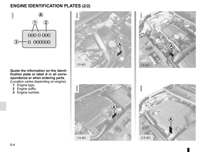
Depending on the vehicle, this is com-
posed of:
– the ABS (anti-lock braking
system);
– electronic stability control ESC
with understeer control and trac-
tion control;
– emergency brake assist with, de- pending on the vehicle, braking
anticipation;
– hill start assistance.
In an emergency, apply firm and
continuous pressure to the brake
pedal. There is no need to pump
it repeatedly. The ABS will modu-
late the force applied in the braking
system.
These functions are an ad-
ditional aid in the event of
critical driving conditions,
enabling the vehicle behav-
iour to be adapted to suit the driving
conditions.
However, the functions do not take
the place of the driver. They do
not increase the vehicle’s limits
and should not encourage you
to drive more quickly. Therefore,
they can under no circumstances
replace the vigilance or responsibil-
ity of the driver when manoeuvring
the vehicle (the driver must always
be ready for sudden incidents which
may occur when driving).
Your braking systems
are partially operational.
However, it is dangerous
to brake suddenly and
it is essential to stop immediately,
as soon as traffic conditions allow.
Contact an approved dealer.
Operating faults:
–
© and x lit on the instru-
ment panel with the messages
“Check ABS”, “Check braking
system” and “Check ESC” : ABS,
ESC and the emergency brake
assist are deactivated. Braking is
always enabled;
–
x, D, © and ® lit
up on the instrument panel alongside
the message “Braking system fault”:
this indicates a fault in the braking
system.
In both cases, consult an approved
Dealer.
ABS (anti-lock braking
system)
Under heavy braking, the ABS prevents
the wheels from locking, allowing the
stopping distance to be managed and
keeping control of the vehicle.
Under these circumstances, the vehi-
cle can be steered to avoid an obstacle
whilst braking. In addition, this system
can increase stopping distances, par-
ticularly on roads with low surface grip
(wet ground etc.).
You will feel a pulsation through the
brake pedal each time the system is
activated. The ABS does not in any
way improve the vehicle’s physical per-
formance relating to the road surface
and road-holding. It is still essential to
follow the rules of good driving practice
(such as driving at a safe distance from
the vehicle in front, etc.).
Page 107 of 236

2.25
DRIVER CORRECTION DEVICES AND AIDS (2/4)
Electronic stability control
ESC with understeer control
and traction control
Electronic stability control ESC
This system helps you to keep control
of the vehicle in critical driving condi-
tions (avoiding an obstacle, loss of grip
on a bend, etc.).
Operating principle
A sensor in the steering wheel detects
the direction selected by the driver.
Other sensors throughout the vehicle
measure the actual direction.
The system compares driver input to
the actual trajectory of the vehicle and
corrects the trajectory if necessary by
controlling the braking of certain wheels
and/or engine power. In the event that
the system is engaged, indicator light
flashes on the instrument panel.Understeer control
This system optimises the action of the
ESC in the case of pronounced under-
steer (loss of front axle road holding).
Traction control
This system helps to limit wheelspin of
the drive wheels and to control the ve-
hicle when pulling away accelerating or
decelerating.
Operating principle
Using the wheel sensors, the system
measures and compares the speed of
the drive wheels at all times and slows
down their over-rotation. If a wheel is
starting to slip, the system brakes au-
tomatically until the drive supplied be-
comes compatible with the level of grip
under the wheel again.
The system also adjusts the engine
speed to the grip available under the
wheels, independently of the pressure
exerted on the accelerator pedal. Operating faults
When the system detects an operat-
ing fault the message “Check ESC” and
warning light
© appear on the in-
strument panel.
In this case, the ESC and traction
control system are deactivated. Consult
an authorised dealer.
Page 108 of 236

2.26
The traction control system offers ad-
ditional safety. It is recommended that
you do not drive with the function di-
sabled. Correct this as soon as pos-
sible by pressing the switch 1 again.
Note: the function is reactivated auto-
matically when the ignition is switched
on or when a speed of approximately
24 mph (40 km/h) is exceeded.
Emergency brake assist
This system supplements the ABS
and helps reduce vehicle stopping dis-
tances.
Operating principle
The system is for detecting an emer-
gency braking situation. In this case,
the braking assistance immediately de-
velops maximum power and may trig-
ger ABS regulation.
ABS braking is maintained as long as
the brake pedal is applied.
Hazard warning lights switching on
Depending on the vehicle, these may
light up in the event of sudden decel-
eration.
Operating faults
When the system detects an operat-
ing fault the message “Check brak-
ing system” appears on the instrument
panel along with the
© warning
light.
Consult an approved dealer.
Braking anticipation
Depending on the vehicle, when you
rapidly release the accelerator, the
system anticipates the braking ma-
noeuvre in order to reduce stopping
distances.
Special cases
When using the cruise control:
– if you use the accelerator, when you release it, the system may be trig-
gered;
– if you do not use the accelerator, the system will not be triggered.
DRIVER CORRECTION DEVICES AND AIDS (3/4)
Disabling the traction control
system
In some situations (driving on very wet
ground: snow, mud, etc. or driving with
snow chains fitted), the system may
reduce the engine output to limit wheel-
spin. If this is not required, it is possible
to deactivate the function by pressing
switch 1.
The message “Traction control off” is
displayed on the instrument panel to
inform you.
1
Page 109 of 236

2.27
DRIVER CORRECTION DEVICES AND AIDS (4/4)
Hill start assistance
This device assists the driver when
starting on hills (ascending or descend-
ing). It prevents the vehicle from rolling
forwards or backwards by automatically
applying the brakes when the driver lifts
their foot off the brake pedal to depress
the accelerator pedal.
System operation
It only operates when the gear lever is
in a position other than neutral (other
than N or P for automatic transmis-
sions) and the vehicle is completely
stationary (brake pedal depressed).
The system holds the vehicle for ap-
proximately 2 seconds. The brakes are
then gradually released (the vehicle will
move according to the slope).The hill start assistance
system cannot completely
prevent the vehicle from
rolling backwards in all sit-
uations (extremely steep gradients,
etc.).
In all cases, the driver may depress
the brake pedal to prevent the ve-
hicle from rolling forwards or back-
wards.
The hill start assistance function
should not be used for prolonged
stops: use the brake pedal.
This function is not designed to im-
mobilise the vehicle permanently.
If necessary, use the brake pedal to
stop the vehicle.
The driver must remain particularly
vigilant when driving on slippery or
low-grip surfaces and/or on hills.
Risk of serious injury.
Page 110 of 236
2.28
CRUISE CONTROL/SPEED LIMITER: speed limiter function (1/3)
The speed limiter function helps you
stay within the driving speed limit that
you choose, known as the limit speed.Controls
1 Main “On/Off” switch.
2 Limit speed activation, storage and increase switch (+).
3 Decrease limit speed (-).
4 Switch the function to standby (with memorisation of the limit speed) (O).
5 Activation and recall of stored limit speed (R).
Switching on
Press the side switch 1 . Warning
light 7 comes on, lit orange, and the
message “Speed limiter” appears on
the instrument panel, accompanied by
dashes in zone 6 to indicate that the
speed limiter function is activated and
waiting to store a speed limit.
To store the current speed, press
switch 2 (+): The limited speed will
appear in zone 6. The minimum stored
speed is 20 mph (30 km/h).
76
1
2354
Page 111 of 236

2.29
Driving
When a limited speed has been stored
and this speed is not reached, driving is
similar to driving a vehicle without the
speed limiter function.
Once you have reached the stored
speed, no effort on the accelera-
tor pedal will allow you to exceed
the programmed speed except in an
emergency (refer to information on
“Exceeding the limit speed”).
Varying the limit speed
The limit speed may be changed by re-
peatedly pressing:
– switch 2 (+) to increase the speed;
– switch 3 (-) to decrease the speed.
Exceeding the limit speed
It is possible to exceed the limit speed
at any moment. To do this: press the
accelerator pedal firmly and fully
(beyond the kickdown point).
While driving over the speed limit, the
speed limit flashes on the instrument
panel, the display area A goes red
and, depending on the vehicle, a beep
sounds.
Then, as far as is possible, release
the accelerator pedal: the speed lim-
iter function will return as soon as you
reach a speed lower than the stored
speed.
Limited speed cannot be maintained
If driving up or down a steep gradient,
the system is unable to maintain the
limited speed: the stored speed flashes
on the instrument panel, the area A
goes red, and depending on the vehi-
cle, a warning beep sounds.
The speed limiter function is
in no way linked to the brak-
ing system.
A
CRUISE CONTROL/SPEED LIMITER: speed limiter function (2/3)
2354
Page 112 of 236
2.30
Recalling the limit speed
If a speed has been stored, it can be re-
called by pressing switch 5 (R).
CRUISE CONTROL/SPEED LIMITER: speed limiter function (3/3)
Putting the function on
standby
The speed limiter function is deacti-
vated when you press switch 4 (O). In
this case, the speed limit will remain
stored and is no longer displayed in
zone 6 and the message “Memorised”
along with the stored speed will appear
on the display.
1
When the speed limiter is put on
standby, pressing switch 2 (+) re-
activates the function without taking
into account the stored speed: it is
the speed at which the vehicle is
moving that is taken into account.
Switching off the function
The speed limiter function is deacti-
vated if you press switch 1: in this case
a speed is no longer stored. The in-
strument panel orange indicator light 7
goes out to confirm that the function is
deactivated.
6
2354
7