Page 237 of 298

5.5
TYRE PRESSURE KIT (2/3)
In the event of a puncture, use the kit
located in the boot, underneath the
boot carpet.
With the engine running and the
parking brake applied,
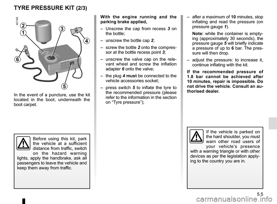
– Unscrew the cap from recess 3 on
the bottle;
– unscrew the bottle cap 2;
– screw the bottle 2 onto the compres- sor at the bottle recess point 3;
– unscrew the valve cap on the rele- vant wheel and screw the inflation
adapter 6 onto the valve;
– the plug 4 must be connected to the
vehicle accessories socket;
– press switch 5 to inflate the tyre to
the recommended pressure (please
refer to the information in the section
on “Tyre pressure”);
Before using this kit, park
the vehicle at a sufficient
distance from traffic, switch
on the hazard warning
lights, apply the handbrake, ask all
passengers to leave the vehicle and
keep them away from traffic.
If the vehicle is parked on
the hard shoulder, you must
warn other road users of
your vehicle’s presence
with a warning triangle or with other
devices as per the legislation apply-
ing to the country you are in.
– after a maximum of 10 minutes, stop inflating and read the pressure (on
pressure gauge 1).
Note: while the container is empty-
ing (approximately 30 seconds), the
pressure gauge 5 will briefly indicate
a pressure of up to 6 bar. The pres-
sure will then drop.
– adjust the pressure: to increase it, continue inflating with the kit.
If the recommended pressure of
1.8 bar cannot be achieved after
10 minutes, repair is impossible. Do
not drive the vehicle. Consult an au-
thorised dealer.
4
2
13
5
6
Page 241 of 298

5.9
Continue to crank the jack so that the
baseplate is correctly positioned (it
should be underneath the vehicle and
aligned with the jack head).
Switch on the hazard warn-
ing lights.
Keep the vehicle away from
traffic and on a level surface
where it will not slip.
Apply the parking brake and engage
a gear (first or reverse, or P for auto-
matic transmissions).
Ask all the passengers to leave the
vehicle and keep them away from
traffic.
CHANGING A WHEEL (1/2)
Vehicles equipped with a jack
and wheelbrace
If necessary, remove the wheel trim.
Use the wheelbrace 1 to slacken off the
wheel bolts. Position it so as to be able
to push from above.
Crank up the jack 3 by hand to align
the jack head between the 2 jacking
points 2 closest to the relevant wheel.
If the vehicle is not equipped with a
jack or wheelbrace, you can obtain
these from your approved dealer.
If the vehicle is parked on
the hard shoulder, you must
warn other road users of
your vehicle’s presence
with a warning triangle or with other
devices as per the legislation apply-
ing to the country you are in.
1
2
3
Page 244 of 298

5.12
TYRES (2/3)
Tyre pressures
Adhere to the tyre pressures (including
the emergency spare wheel). The tyre
pressures should be checked at least
once a month and additionally before
any long journey (refer to the label af-
fixed to the edge of the driver’s door).The pressures should be checked cold:
ignore higher pressures which may be
reached in hot weather or following a
high speed journey.
If the tyre pressures cannot be checked
when the tyres are
cold, increase the
pressures from 0.2 to 0.3 bar (or 3 PSI).
Never deflate a hot tyre.
Special note
Depending on the vehicle, there may
be an adapter which needs to be posi-
tioned on the valve before air is added. Vehicle fitted with a tyre pressure
monitoring system
In cases of under-inflation (puncture,
low pressure, etc.), warning light
�
lights up on the instrument panel.
Please refer to the information on the
“Tyre pressure monitoring system” in
Section 2.
Emergency spare wheel
Refer to the information on “Puncture”
and “Changing a wheel” in Section 5.
Incorrect tyre pressures
lead to abnormal tyre wear
and unusually hot running.
These are factors which
may seriously affect safety and lead
to:
– poor road holding,
– risk of bursting or tread separa- tion.
The pressure depends on the load
and the speed of use. Adjust the
pressure according to the condi-
tions of use (refer to the label affixed
to the edge of the driver’s door).
Please be aware that a
poorly tightened or miss-
ing valve cap can make the
tyres less airtight and lead
to pressure loss.
Always use valve caps identical to
those fitted originally and tighten
them fully.
Page 246 of 298

5.14
After replacing the bulbs, you must put
the air duct A back into position. To do
this, perform the above operation in re-
verse.
FRONT HEADLIGHTS: changing bulbs (1/3)
The engine may be hot
when carrying out opera-
tions in close proximity. In
addition, the engine cooling
fan can come on at any moment.
Risk of injury.Before performing any
action in the engine com-
partment, the ignition must
be switched off (please see
the information on “Starting, stop-
ping the engine” in Section 2).
Accessing the bulbs
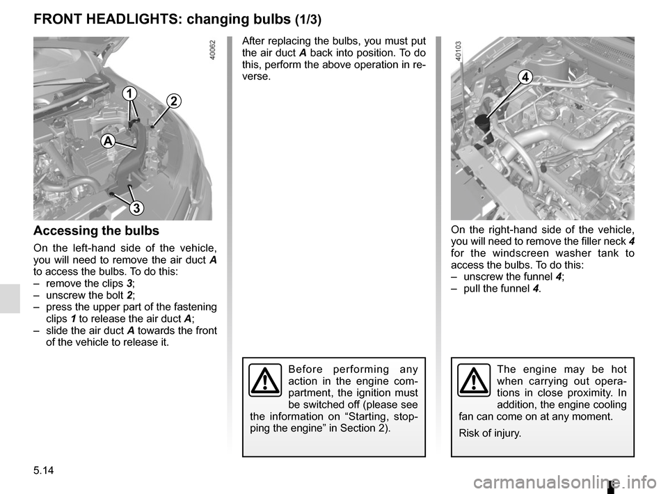
On the left-hand side of the vehicle,
you will need to remove the air duct A
to access the bulbs. To do this:
– remove the clips 3;
– unscrew the bolt 2;
– press the upper part of the fastening clips 1 to release the air duct A;
– slide the air duct A towards the front of the vehicle to release it.
On the right-hand side of the vehicle,
you will need to remove the filler neck 4
for the windscreen washer tank to
access the bulbs. To do this:
– unscrew the funnel 4;
– pull the funnel 4.
4
3
2
A
1
Page 247 of 298
5.15
FRONT HEADLIGHTS: changing bulbs (2/3)Halogen main beam headlight
To change the bulb:
– remove cover C;
– turn the bulb holder a quarter turn 7;
– remove the bulb.
Bulb type: H7.
It is essential to use anti-U.V. 55W
bulbs so as not to damage the plastic
on the headlights.
Do not touch the bulb glass. Hold it
by its base.
When the bulb has been changed,
make sure you refit the cover correctly.6
7
Halogen dipped beam
headlight
To change the bulb:
– remove cover B;
– turn the bulb holder a quarter turn 6;
– remove the bulb.
Bulb type: H7.
CB
Direction indicator lights
Turn the bulb holder 5 a quarter of a
turn and take out the bulb.
Bulb type: PY21W.
Once the bulb has been replaced,
check that it is properly secured.
5
The bulbs are under pres-
sure and can break when
replaced.
Risk of injury.
Page 248 of 298
5.16
Front fog lights 10
The front bumper needs to be removed;
consult an approved Dealer.
Bulb type: H8.
The bulbs are under pres-
sure and can break when
replaced.
Risk of injury.
FRONT HEADLIGHTS: changing bulbs (3/3)
To comply with local legislation, or
as a precaution, you can obtain an
emergency kit containing a set of
spare bulbs and fuses from an ap-
proved dealer.
Any operation on (or modi-
fication to) the electrical
system must be performed
by an approved dealer
since an incorrect connection might
damage the electrical equipment
(harness, components and in partic-
ular the alternator). In addition, your
Dealer has all the parts required for
fitting these units.
LED dipped beam/main beam
headlights 9
Please see an authorised dealer.
Daytime running lights and
side lights 8
Please see an authorised dealer.
10
Additional lights
If you wish to fit fog lights to your ve-
hicle, please see an authorised dealer.
8
9
Page 249 of 298
5.17
REAR AND SIDE LIGHTS: changing bulbs (1/3)
Side lights and brake lights
Consult an approved Dealer.
1
Refit the bulb holder and push the unit
as far as it will go, until it locks into
place.
Check that the light is properly locked
in position.
Tighten screws 2.Direction indicators 1
Open the boot lid and remove screws 2.
Pull on the outside A of the light and
remove the rear light unit.
Turn the bulb holder a quarter of a
turn 3.
Remove the bulb.
Bulb type: PY21.
2
A3
Page 250 of 298
5.18
Replace the bulb 5.
Bulb type: H21W.
Refitting
To refit, proceed in the reverse order,
taking care not to damage the wiring.
The bulbs are under pres-
sure and can break when
replaced.
Risk of injury.
Reversing lights
From the boot, unclip the cover on the
interior trim of the boot lid 4 using a
screwdriver or similar tool.
REAR AND SIDE LIGHTS: changing bulbs (2/3)
54