Page 111 of 347
CAUTION!
If the “Water In Fuel Indicator Light” remains on, DO
NOT START the engine before you drain water from
the fuel filters to avoid engine damage.
If the “Water In Fuel Indicator Light” comes on and a
single chime is heard while you are driving, or with the
ignition in the ON position, there may be a problem with
your water separator wiring or sensor. See your autho-
rized dealer for service.
Upon proper draining of the water from the fuel filter, the
“Water In Fuel Indicator Light” will remain illuminated
for approximately 10 seconds. If the water was drained
while the engine was running, the “Water In Fuel Indi-
cator Light” may remain on for approximately three
minutes. NOTE:
Care should be taken in disposing of used fluids
from your vehicle. Used fluids, indiscriminately dis-
carded, can present a problem to the environment. Con-
tact an authorized dealer, service station, or government
agency for advice on recycling programs and for where
used fluids and filters can be properly disposed of in
your area.
Drain the fuel/water separator filter when the “Water In
Fuel Indicator Light” is ON. Within 10 minutes of vehicle
shutdown, turn the filter drain valve (located on the
bottom of the filter housing) counterclockwise to drain
fuel/water, then turn the ignition switch to the ON
position, and allow any accumulated water to drain.
Leave the drain valve open until all water and contami-
nants have been removed. When clean fuel is visible,
close the drain valve by turning it clockwise, and turn the
ignition switch to OFF.
5
MAINTAINING YOUR VEHICLE 109
Page 113 of 347
3. Open the water drain valve, and let any accumulatedwater drain.
4. Close the water drain valve.
5. Remove bottom cover using a strap wrench. Rotate counterclockwise for removal. Remove the used o-ring
and discard it.
6. Remove the used filter cartridge from the housing and dispose of it according to your local regulations.
7. Wipe the sealing surfaces of the lid and housing clean.
8. Install a new o-ring into the ring groove on the filter housing and lubricate with clean engine oil.
NOTE: WIF (Water In Fuel) sensor is re-usable. Service
kit comes with new o-ring for filter canister and WIF
sensor.Priming If The Engine Has Run Out Of Fuel
WARNING!
Do not open the high pressure fuel system with the
engine running. Engine operation causes high fuel
pressure. High pressure fuel spray can cause serious
injury or death.
1. Add a substantial amount of fuel to the tank, approxi- mately 2 to 5 gal (8L to 19L).
2. Press ignition switch twice without your foot on brake to put vehicle in Run position. This will activate the in
tank fuel pump for approximately 30 seconds. Repeat
this process twice.
3. Start the engine using the “Normal Starting” proce- dure. Refer to “Starting Procedures” in “Starting and
Operating” for further information.
5
MAINTAINING YOUR VEHICLE 111
Page 122 of 347
•Do not change the thermostat for Summer or Winter
operation. If replacement is ever necessary, install ONLY
the correct type thermostat. Other designs may result in
unsatisfactory engine coolant (antifreeze) performance,
poor gas mileage, and increased emissions.
Charge Air Cooler — Inter-Cooler
The charge air cooler is positioned in front of the radiator
and the air conditioner condenser. Air enters the engine
through the air cleaner and passes through the turbo-
charger, where it is pressurized. This pressurized air
rapidly reaches high temperature. The air is then directed
through a hose to the charge air cooler and through
another hose to the intake manifold of the engine. This
cooling process enables more efficient burning of fuel
resulting in fewer emissions.
To guarantee optimum performance of the system, keep
the surfaces of the charge air cooler, condenser and radiator
clean and free of debris. Periodically check the hoses leading to and from the charge air cooler for cracks or loose
clamps resulting in loss of pressure and reduced engine
performance.
Brake System
Brake Master Cylinder — Brake Fluid Level Check
The fluid level of the master cylinder should be checked
when performing under the hood service, or immedi-
ately if the “Brake System Warning Light” indicates
system failure.
The brake master cylinder has a translucent plastic
reservoir. On the outboard side of the reservoir, there is a
“MAX” mark and a “MIN” mark. The fluid level must be
kept within these two marks. Do not add fluid above the
full mark because leakage may occur at the cap.
With disc brakes, the fluid level can be expected to fall as
the brake linings wear. However, an unexpected drop in
fluid level may be caused by a leak and a system check
should be conducted.
120 MAINTAINING YOUR VEHICLE
Page 126 of 347
Component Fluid, Lubricant, or Genuine Part
Fuel Selection Use good quality diesel fuel from a reputable supplier in your vehicle. Federal law requiresthat you must fuel this vehicle with Ultra Low Sulfur Highway Diesel fuel (15 ppm Sulfur
maximum) and prohibits the use of Low Sulfur Highway Diesel fuel (500 ppm Sulfur
maximum) to avoid damage to the emissions control system.
For most year-round service, No. 2 diesel fuel meeting ASTM specification D-975 Grade S15 will
provide good performance. We recommend you use a blend of up to 5% biodiesel, meeting
ASTM specification D-975 with your diesel engine.
This vehicle is compatible with biodiesel
blends greater than 5% but no greater than 20% biodiesel meeting ASTM specification
D-7467 provided the shortened maintenance intervals are followed as directed.
Diesel Exhaust
Fluid MOPAR® Diesel Exhaust Fluid (API Certified) (DEF) or equivalent that has been API
Certified to the ISO 22241 standard. Use of fluids not API Certified to ISO 22241 may result
in system damage.
124 MAINTAINING YOUR VEHICLE
Page 130 of 347

MAINTENANCE SCHEDULE
Your vehicle is equipped with an automatic oil change
indicator system. The oil change indicator system will
remind you that it is time to take your vehicle in for
scheduled maintenance.
Based on engine operation conditions, the oil change
indicator message will illuminate. This means that ser-
vice is required for your vehicle. Operating conditions
such as frequent short-trips, trailer tow, extremely hot or
cold ambient temperatures will influence when the “Oil
Change Required” message is displayed. Severe Operat-
ing Conditions can cause the change oil message to
illuminate as early as 3,500 miles (5,600 km) since last
reset. Have your vehicle serviced as soon as possible,
within the next 500 miles (805 km).
Your authorized dealer will reset the oil change indicator
message after completing the scheduled oil change. If a
scheduled oil change is performed by someone otherthan your authorized dealer, the message can be reset by
referring to the steps described under “Electronic Vehicle
Information Center (EVIC)” or “Driver Information Dis-
play (DID)” in “Understanding Your Instrument Panel”
for further information.
NOTE:
Under no circumstances should oil change inter-
vals exceed 10,000 miles (16,000 km) or twelve months,
whichever comes first.
Once A Month Or Before A Long Trip:
• Check engine oil level
• Check windshield washer fluid level
• Check the tire inflation pressures and look for unusual
wear or damage
• Check the fluid levels of the coolant reservoir, brake
master cylinder and power steering, and fill as needed
• Check function of all interior and exterior lights
128 MAINTENANCE SCHEDULE
Page 135 of 347
WARNING!
•You can be badly injured working on or around a
motor vehicle. Do only service work for which you
have the knowledge and the right equipment. If you
have any doubt about your ability to perform a service
job, take your vehicle to a competent mechanic.
• Failure to properly inspect and maintain your ve-
hicle could result in a component malfunction and
effect vehicle handling and performance. This
could cause an accident.
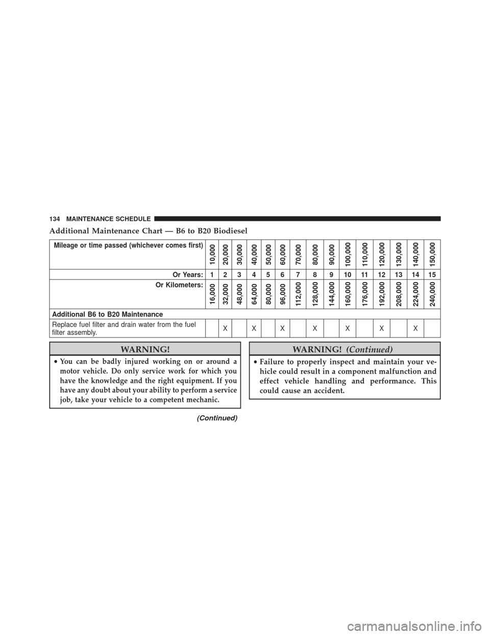
Additional Maintenance — B6 To B20 Biodiesel
NOTE:
• Under no circumstances should oil change intervals
exceed 8,000 miles (12 875 km) or six months, which-
ever comes first when using Biodiesel blends greater
than 5% (B5).
• The owner is required to monitor mileage for B6-B20
biodiesel, the automatic oil change indicator system
does not reflect the use of biofuels.
6
MAINTENANCE SCHEDULE 133
Page 136 of 347
Additional Maintenance Chart — B6 to B20 Biodiesel
Mileage or time passed (whichever comes first)
10,000
20,000
30,000
40,000
50,000
60,000
70,000
80,000
90,000
100,000
110,000
120,000
130,000
140,000
150,000
Or Years: 1 2 3 4 5 6 7 8 9 10 11 12 13 14 15
Or Kilometers:
16,000
32,000
48,000
64,000
80,000
96,000
112,000
128,000
144,000
160,000
176,000
192,000
208,000
224,000
240,000
Additional B6 to B20 Maintenance
Replace fuel filter and drain water from the fuel
filter assembly. XXX X X X X
WARNING!
•You can be badly injured working on or around a
motor vehicle. Do only service work for which you
have the knowledge and the right equipment. If you
have any doubt about your ability to perform a service
job, take your vehicle to a competent mechanic.
(Continued)
WARNING! (Continued)
•Failure to properly inspect and maintain your ve-
hicle could result in a component malfunction and
effect vehicle handling and performance. This
could cause an accident.
134 MAINTENANCE SCHEDULE
Page 143 of 347
•Any chassis/suspension or tire size modifications to the
vehicle will effect the performance of the Adaptive
Cruise Control and Forward Collision Warning System.
This information cannot be erased and will stay in the
system’s memory even if the modification is removed.
This information can be retrieved by FCA US LLC, and
service and repair facilities, when servicing your vehicle.
This information may be used to determine if repair will
be covered by the New Vehicle Limited Warranty. There is a probability that the use of a “performance
chip” will prohibit the engine from starting. In this
instance, the vehicle will need to be serviced by a
authorized dealer in order to return the vehicle to it’s
factory settings.
1
INTRODUCTION 141