Page 78 of 292
76
Partner-2-VU_en_Chap04_Ergonomie_ed01-2015
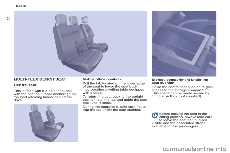
Mobile office position
Pull the tab located on the lower edge
of the seat to lower the seat back
incorporating a writing table equipped
with a strap.
To return the seat back to the upright
position, pull the tab and guide the seat
back until it locks.
During the operations, take care not to
trap the tab under the seat cushion.Storage compartment under the
seat cushion
Raise the centre seat cushion to gain
access to the storage compartment.
This space can be made secure by
fitting a padlock (not supplied).MULTI-FLEx BENCH SEAT
Centre seat
Before locking the seat in the
sitting position, always take care
to leave the seat belt buckles
visible and the associated straps
available for the passengers.
This is fitted with a 3-point seat belt
with the seat belt upper anchorage on
the load retaining ladder behind the
driver.
Seats
Page 82 of 292
80
Partner-2-VU_en_Chap04_Ergonomie_ed01-2015
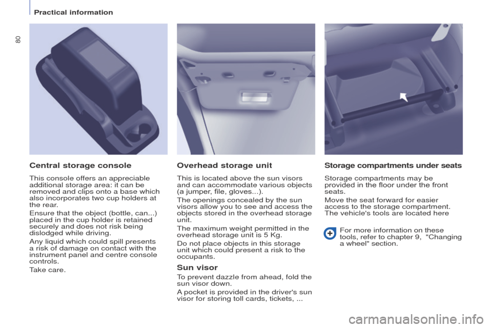
Overhead storage unit
This is located above the sun visors
and can accommodate various objects
(a jumper, file, gloves...).
The openings concealed by the sun
visors allow you to see and access the
objects stored in the overhead storage
unit.
The maximum weight permitted in the
overhead storage unit is 5 Kg.
Do not place objects in this storage
unit which could present a risk to the
occupants.
Central storage console
This console offers an appreciable
additional storage area: it can be
removed and clips onto a base which
also incorporates two cup holders at
the rear.
Ensure that the object (bottle, can...)
placed in the cup holder is retained
securely and does not risk being
dislodged while driving.
Any liquid which could spill presents
a risk of damage on contact with the
instrument panel and centre console
controls.
Take care.
Sun visor
To prevent dazzle from ahead, fold the
sun visor down.
A pocket is provided in the driver's sun
visor for storing toll cards, tickets, ...
Storage compartments under seats
Storage compartments may be
provided in the floor under the front
seats.
Move the seat forward for easier
access to the storage compartment.
The vehicle's tools are located here
For more information on these
tools, refer to chapter
9, "Changing
a wheel" section.
Practical information
Page 85 of 292
83
Partner-2-VU_en_Chap04_Ergonomie_ed01-2015
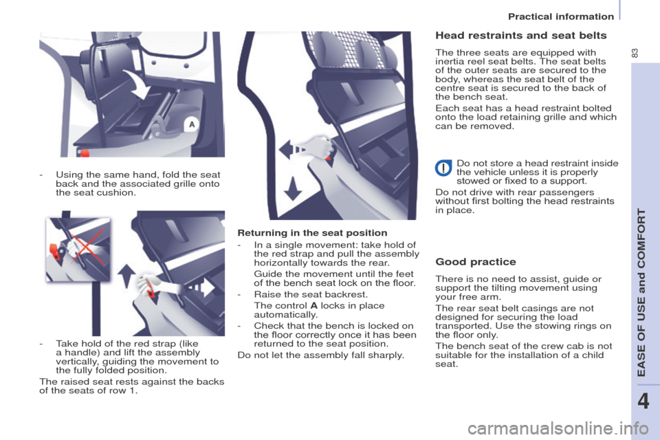
Returning in the seat position
-
In a single movement: take hold of
the red strap and pull the assembly
horizontally towards the rear
.
Guide the movement until the feet
of the bench seat lock on the floor
.
-
Raise the seat backrest.
The control
A locks in place
automatically.
-
Check that the bench is locked on
the floor correctly once it has been
returned to the seat position.
Do not let the assembly fall sharply
.
Good practice
There is no need to assist, guide or
support the tilting movement using
your free arm.
The rear seat belt casings are not
designed for securing the load
transported. Use the stowing rings on
the floor only.
The bench seat of the crew cab is not
suitable for the installation of a child
seat.
-
Using the same hand, fold the seat
back and the associated grille
onto
the seat cushion.
-
T
ake hold of the red strap (like
a handle) and lift the assembly
vertically, guiding the movement to
the fully folded position.
The raised seat rests against the backs
of the seats of row 1.
Head restraints and seat belts
The three seats are equipped with
inertia reel seat belts. The seat belts
of the outer seats are secured to the
body, whereas the seat belt of the
centre seat is secured to the back of
the bench seat.
Each seat has a head restraint bolted
onto the load retaining grille and which
can be removed.
Do not store a head restraint inside
the vehicle unless it is properly
stowed or fixed to a support.
Do not drive with rear passengers
without first bolting the head restraints
in place.
Practical information
EASE OF USE and COMFORT
4
Page 87 of 292
85
Partner-2-VU_en_Chap04_Ergonomie_ed01-2015
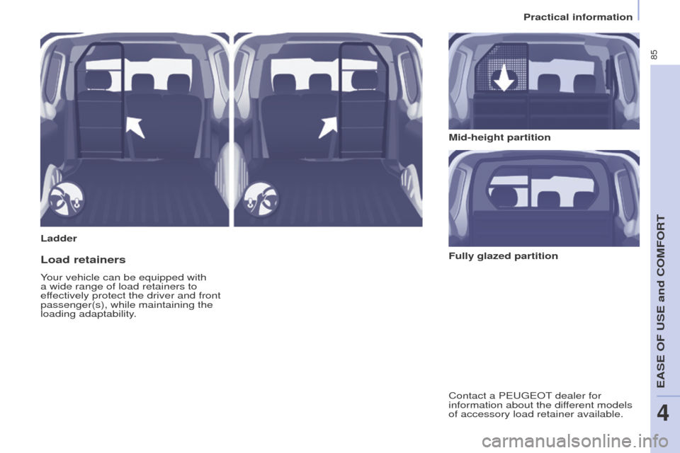
LadderMid-height partition
Load retainers
Your vehicle can be equipped with
a wide range of load retainers to
effectively protect the driver and front
passenger(s), while maintaining the
loading adaptability.
Contact a PEUGEOT dealer for
information about the different models
of accessory load retainer available. Fully glazed partition
Practical information
EASE OF USE and COMFORT
4
Page 88 of 292
86
Partner-2-VU_en_Chap04_Ergonomie_ed01-2015
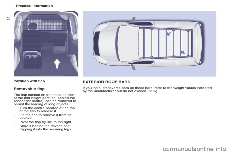
Removable flap
The flap located on the panel section
of the mid-height partition, behind the
passenger seat(s), can be removed to
permit the loading of long objects.
-
T
urn the control located at the top
of the flap to release it.
-
Lift the flap to remove it from its
location.
-
Pivot the flap by 90° to the right.
-
Store it behind the driver's seat,
clipping it into the securing lugs.
ExTERIOR ROOF BARS
If you install transverse bars on these bars, refer to the weight values\
indicated
by the manufacturer but do not exceed: 75 kg.
Partition with flap
Practical information
Page 91 of 292
89
Partner-2-VU_en_Chap04_Ergonomie_ed01-2015
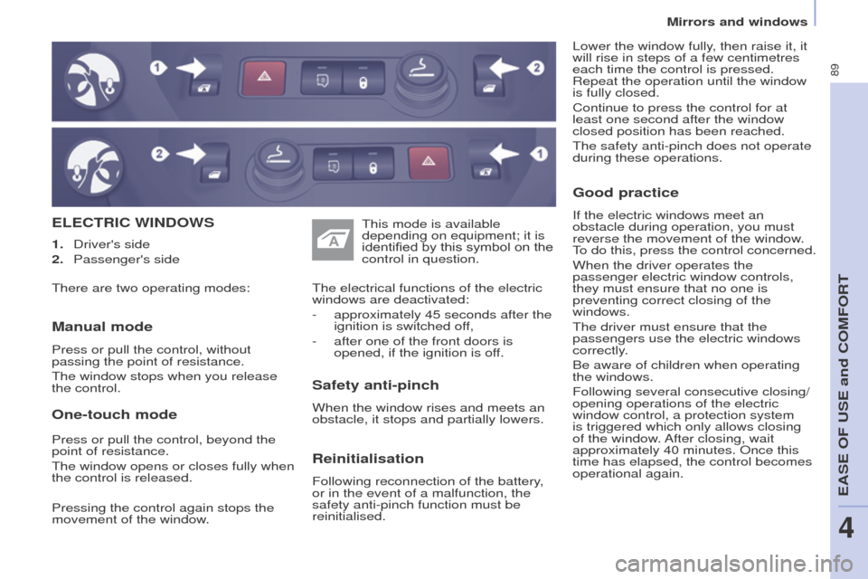
ELECTRIC WINDOWS
Safety anti-pinch
When the window rises and meets an
obstacle, it stops and partially lowers. The electrical functions of the electric
windows are deactivated:
-
approximately 45 seconds after the
ignition is switched of
f,
-
after one of the front doors is
opened, if the ignition is of
f.
Manual mode
Press or pull the control, without
passing the point of resistance.
The window stops when you release
the control. This mode is available
depending on equipment; it is
identified by this symbol on the
control in question.
1.
Driver's side
2.
Passenger's side
Reinitialisation
Following reconnection of the battery,
or in the event of a malfunction, the
safety anti-pinch function must be
reinitialised.
Good practice
If the electric windows meet an
obstacle during operation, you must
reverse the movement of the window.
To do this, press the control concerned.
When the driver operates the
passenger electric window controls,
they must ensure that no one is
preventing correct closing of the
windows.
The driver must ensure that the
passengers use the electric windows
correctly.
Be aware of children when operating
the windows.
Following several consecutive closing/
opening operations of the electric
window control, a protection system
is triggered which only allows closing
of the window. After closing, wait
approximately 40 minutes. Once this
time has elapsed, the control becomes
operational again. Lower the window fully, then raise it, it
will rise in steps of a few centimetres
each time the control is pressed.
Repeat the operation until the window
is fully closed.
Continue to press the control for at
least one second after the window
closed position has been reached.
The safety anti-pinch does not operate
during these operations.
There are two operating modes:
One-touch mode
Press or pull the control, beyond the
point of resistance.
The window opens or closes fully when
the control is released.
Pressing the control again stops the
movement of the window.
Mirrors and windows
EASE OF USE and COMFORT
4
Page 94 of 292
92
Partner-2-VU_en_Chap05_Securite_ed01-2015
Activation / DeactivationMalfunction
In the event of a malfunction, the LED
in the button comes on, accompanied
by an audible signal and a message in
the screen.
Contact a PEUGEOT dealer or
qualified workshop.
Good practice
In bad weather or in winter, ensure that
the sensors are not covered with mud,
ice or snow.
The system will be deactivated
automatically if a trailer is being towed
or if a bicycle carrier is fitted (vehicle
fitted with a towbar or bicycle carrier
recommended by PEUGEOT).
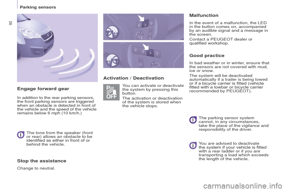
You can activate or deactivate
the system by pressing this
button.
The activation or deactivation
of the system is stored when
the vehicle stops.
The parking sensor system
cannot, in any circumstances,
take the place of the vigilance and
responsibility of the driver.
Engage forward gear
In addition to the rear parking sensors,
the front parking sensors are triggered
when an obstacle is detected in front of
the vehicle and the speed of the vehicle
remains below 6 mph (10 km/h.)
The tone from the speaker (front
or rear) allows an obstacle to be
identified as either in front of or
behind the vehicle.
Stop the assistance
Change to neutral. You are advised to deactivate
the system if your vehicle is fitted
with a rear ladder or if you are
transporting a load which exceeds
the length of the vehicle.
Parking sensors
Page 95 of 292
93
Partner-2-VU_en_Chap05_Securite_ed01-2015
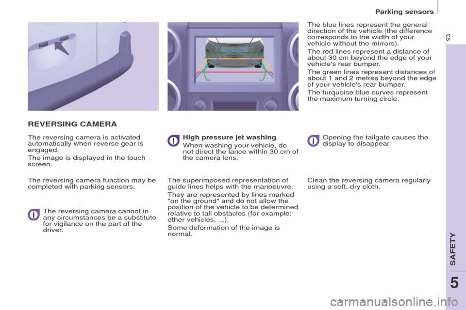
REVERSING CAMERA
The reversing camera is activated
automatically when reverse gear is
engaged.
The image is displayed in the touch
screen.
The reversing camera function may be
completed with parking sensors.The reversing camera cannot in
any circumstances be a substitute
for vigilance on the part of the
driver. High pressure jet washing
When washing your vehicle, do
not direct the lance within 30 cm of
the camera lens.
The superimposed representation of
guide lines helps with the manoeuvre.
They are represented by lines marked
"on the ground" and do not allow the
position of the vehicle to be determined
relative to tall obstacles (for example:
other vehicles, ...).
Some deformation of the image is
normal. The blue lines represent the general
direction of the vehicle (the difference
corresponds to the width of your
vehicle without the mirrors).
The red lines represent a distance of
about 30 cm beyond the edge of your
vehicle's rear bumper.
The green lines represent distances of
about 1 and 2 metres beyond the edge
of your vehicle's rear bumper.
The turquoise blue curves represent
the maximum turning circle.
Opening the tailgate causes the
display to disappear.
Clean the reversing camera regularly
using a soft, dry cloth.
Parking sensors
SAFETY
5