Page 144 of 276

142
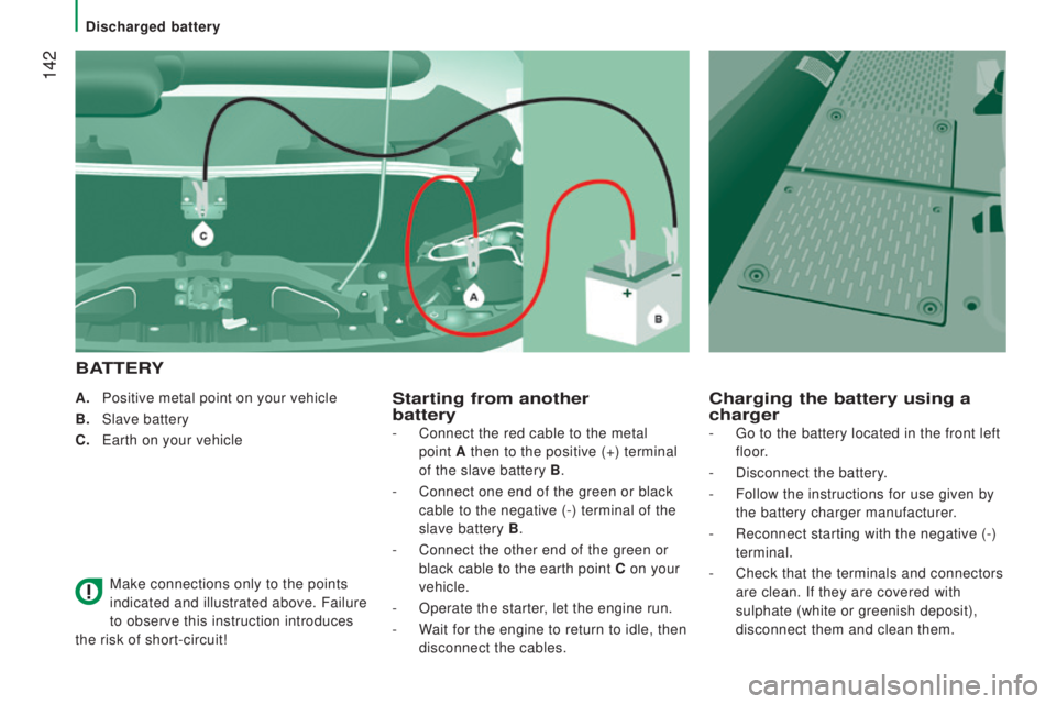
A. Positive metal point on your vehicle
B.
Slave battery
c.
e
arth on your vehicle
Make connections only to the points
indicated and illustrated above. Failure
to observe this instruction introduces
the risk of short-circuit!Starting from another
battery
B
AttErY
c
harging the battery using a
charger
- Connect the red cable to the metal
point
A then to the positive (+) terminal
of the slave battery
B.
-
Connect one end of the green or black
cable to the negative (-) terminal of the
slave battery B .
-
Connect the other end of the green or
black cable to the earth point
c on your
vehicle.
-
Operate the starter, let the engine run.
-
Wait for the engine to return to idle, then
disconnect the cables. -
go to the battery located in the front left
floor.
-
Disconnect the battery.
-
Follow the instructions for use given by
the battery charger manufacturer
.
-
Reconnect starting with the negative (-)
terminal.
-
Check that the terminals and connectors
are clean. If they are covered with
sulphate (white or greenish deposit),
disconnect them and clean them.
Discharged battery
Page 145 of 276

143
Access to the battery
unscrew the 6 access cover retaining
screws.
Lift off or remove completely the access
cover.
Press lever 1 downwards to spread the
clamp.
Remove the terminal 2 from the negative (-)
post.
the batteries contain harmful
substances such as sulphuric acid and
lead.
they must be discarded in accordance
with the provisions of the law and must not,
in any circumstances, be discarded with
household waste.
take used batteries to a special collection
point.
the charging operation must be carried
out in a ventilated area away from
naked flames or any possible sources of
sparks to eliminate the risk of explosion
and fire.
Do not attempt to charge a frozen battery: it
must first be thawed to eliminate the risks of
explosion. If the battery has frozen, before
charging it have it checked by a specialist
who will check that the internal components
have not been damaged and that the
container is not cracked, which could mean
that there is a risk of a leak of toxic and
corrosive acid.
Proceed with a slow charge charge at low
current for a maximum pf about 24 hours to
avoid damaging the battery. Before disconnecting the battery, you must
wait for 2 minutes after switching off the
ignition.
Never disconnect a terminal when the
engine is running.
Never charge a battery without first
disconnecting the terminals.
Close the windows and doors before
disconnecting the battery.
After every reconnection of the battery,
switch on the ignition and wait 1 minute
before starting to allow the electronic
systems to be initialised. If slight difficulties
are experienced after this, please contact a
P
eugeOt dealer or a qualified workshop.
Discharged battery
QuICK HeLP
8
Page 146 of 276

144
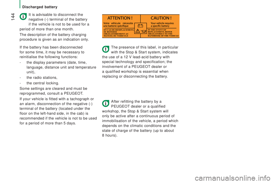
the presence of this label, in particular
with the Stop & Start system, indicates
the use of a 12 V lead-acid battery with
special technology and specification; the
involvement of a P
eugeOt dealer or
a qualified workshop is essential when
replacing or disconnecting the battery.
After refitting the battery by a
P
eugeOt dealer or a qualified
workshop, the Stop & Start system will
only be active after a continuous period of
immobilisation of the vehicle, a period which
depends on the climatic conditions and the
state of charge of the battery (up to about
8 hours).
It is advisable to disconnect the
negative (-) terminal of the battery
if the vehicle is not to be used for a
period of more than one month.
the description of the battery charging
procedure is given as an indication only.
If the battery has been disconnected
for some time, it may be necessary to
reinitialise the following functions:
-
the display parameters (date, time,
language, distance unit and temperature
unit),
-
the radio stations,
-
the central locking.
Some settings are cleared and must be
reprogrammed, consult a P
eugeOt.
If your vehicle is fitted with a tachograph or
an alarm, disconnection of the negative (-)
terminal of the battery (located under the
floor on the left-hand side, in the cab) is
recommended if the vehicle is not to be used
for a period of more than 5 days.
Discharged battery
Page 148 of 276

146FusesA (amps) Allocation
12 7.5Right-hand dipped headlamp
13 7.5Left-hand dipped headlamp
31 5
engine compartment control unit relay - Dashboard control unit relay (ig\
nition switch +)
32 7.5Cabin lighting (battery +)
33 7.5Battery check sensor on Stop & Start version (battery +)
34 7.5Minibus interior lighting - Hazard warning lamps
36 10Audio system -
Air conditioning controls - Alarm -
tachograph - Battery cut-off control unit -
Additional heating programmer (battery +)
37 7.5Brake lamp switch -
third brake lamp Instrument panel (ignition +)
38 20Central door locking (battery +)
42 5ABS control unit and sensor -
ASR sensor - DSC sensor - Brake lamp switch
43 20Windscreen wiper motor (ignition switch +)
47 20Driver's electric window motor
48 20Passenger's electric window motor
49 5Parking sensors control unit - Audio system - Steering mounted controls - Centre and side switch panels\
-
Auxiliary switch panel - Battery cut-off control unit (ignition switch +)
50 7.5Airbags and pre-tensioners control unit
51 5
tachograph - Power steering control unit - Air conditioning - Reversing lamps - W
ater in Diesel sensor -
Air flow sensor (ignition switch +)
53 7.5Instrument panel (battery +)
89 -Not used
90 7.5Left-hand main beam
91 7.5Right-hand main beam
92 7.5Left-hand front foglamp
93 7.5Right-hand front foglamp
Failed fuse
Page 150 of 276
148
Fuses in the engine compartment
Remove the nuts and tilt the box to access
the fuses.
refit the cover carefully after checking or
replacing fuses. Fuses
A (amps) Allocation
1 40ABS pump supply
2 50Diesel pre-heat unit
3 30Ignition switch - Starter motor
4 40Fuel heater
5 20/50Cabin ventilation with additional programmable heating
(battery +)
6 40/60Cabin fan maximum speed (battery +)
7 40/50/60 Cabin fan minimum speed (battery +)
8 40Cabin fan assembly (ignition switch +)
9 15Rear 12 V socket (battery +)
10 15Horn
11 -Not used
14 15Front 12 V socket (battery +)
15 15Cigarette lighter (battery +)
16 -Not used
17 -Not used
18 7.5
engine management control unit (battery +)
19 7.5Air conditioning compressor
20 30Screenwash/headlamp wash pump
21 15Fuel pump supply
22 -Not used
23 30ABS electrovalves
24 7.5Auxiliary switch panel - Door mirror controls and folding
(ignition switch +)
30 15Door mirror heating
Failed fuse
Page 185 of 276
183touch screen Audio-telematic system
Multimedia audio system - Bluetooth® telephone - GPS navigation
Contents
First steps 18 4
gloss
ary
1
85
Steering mounted controls
18
6
Menus
1
87
Radio
18
8
DAB (Digital Audio Broadcasting) radio
19
2
Media
19
4
Navigation
20
2
tele
phone
2
06
Vehicle information
21
0
Settings
2
12
Voice commands
22
2
the s
ystem is protected in such a way that it will only operate in
your vehicle. As as safety measure, the driver must only carry out operations
which require prolonged attention while the vehicle is stationary.
When the engine is switched off and to prevent discharging of
the battery, the system switches off following the activation of
the energy economy mode.
touch Screen Audio - telematic System
AuDIO and teLeMAtICS
10
Page 233 of 276
231Audio system
Multimedia audio system - Bluetooth® telephone
Contents
First steps 232
St
eering mounted controls
233
R
adio
2
34
Media
23
6
tele
phone
23
8
Settings
23
9
Voice commands
24
0
the s
ystem is coded in such a way that it will only operate in
your
v
ehicle. As a safety measure, the driver must only carry out operations
which require prolonged attention while the vehicle is stationary.
When the engine is not running and to prevent discharging of the
battery, the audio system may switch off following activation of
energy economy mode.
Audio System
AuDIO and teLeMAtICS
10
Page 260 of 276
258PrESEntAtIon
the tipper body is raised by a electro-hydraulic unit powered by the
vehicle's battery.
Raising and lowering the the tipper body done is by pressing and
holding the corresponding buttons on the magnetic and portable
remote control mounted on on a carrier in the cab.Power to raise the tipper body is generated by the motor in the electro-\
hydraulic
unit.
The tipper body is lowered by an electrovalve that opens a fluid
return from
the
ram.
A
safety device prevents the tipper body from dropping when static or bei\
ng raised.
tipper body
Page:
< prev 1-8 9-16 17-24