2015 NISSAN VERSA NOTE fog light
[x] Cancel search: fog lightPage 174 of 384
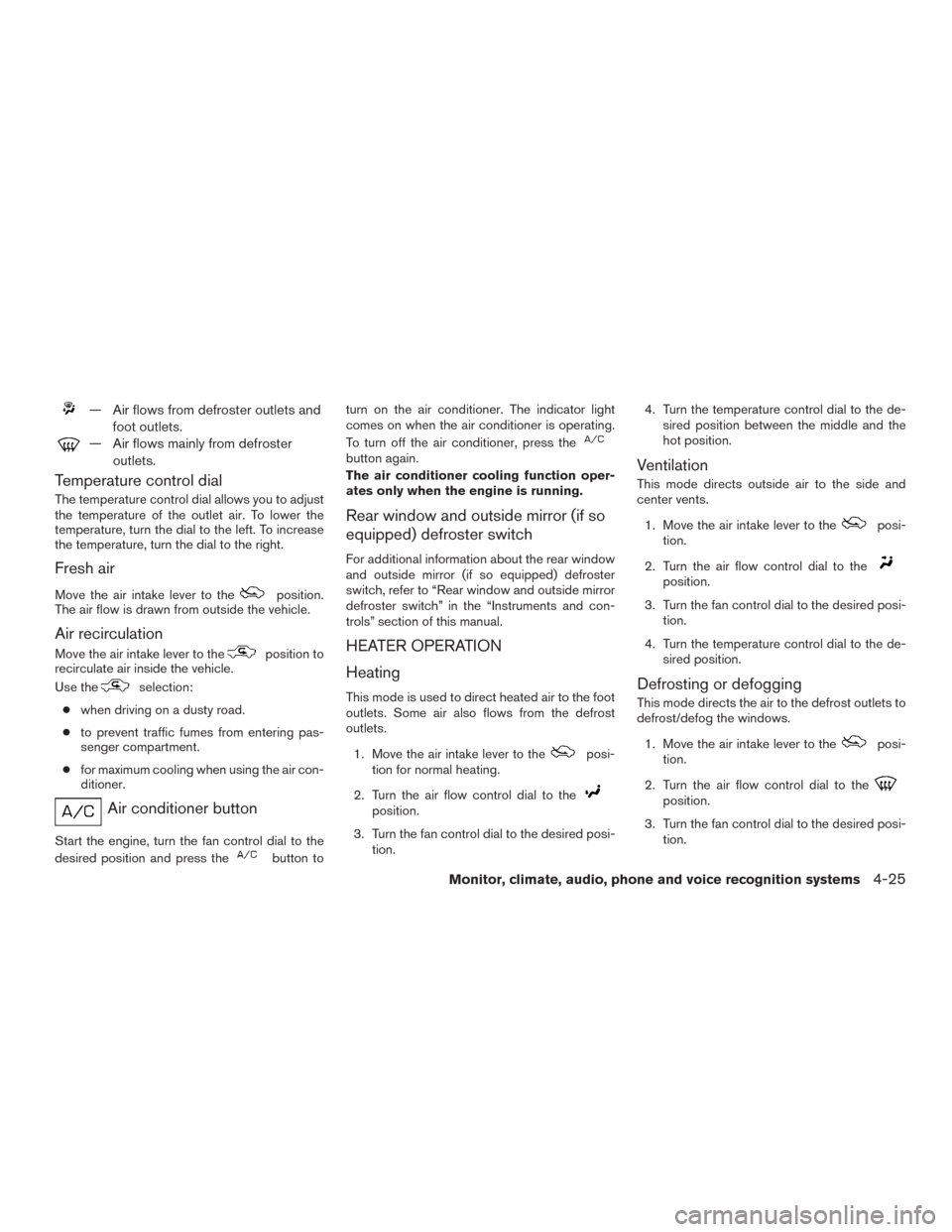
— Air flows from defroster outlets andfoot outlets.
— Air flows mainly from defrosteroutlets.
Temperature control dial
The temperature control dial allows you to adjust
the temperature of the outlet air. To lower the
temperature, turn the dial to the left. To increase
the temperature, turn the dial to the right.
Fresh air
Move the air intake lever to theposition.
The air flow is drawn from outside the vehicle.
Air recirculation
Move the air intake lever to theposition to
recirculate air inside the vehicle.
Use the
selection:
● when driving on a dusty road.
● to prevent traffic fumes from entering pas-
senger compartment.
● for maximum cooling when using the air con-
ditioner.
Air conditioner button
Start the engine, turn the fan control dial to the
desired position and press the
button to turn on the air conditioner. The indicator light
comes on when the air conditioner is operating.
To turn off the air conditioner, press the
button again.
The air conditioner cooling function oper-
ates only when the engine is running.
Rear window and outside mirror (if so
equipped) defroster switch
For additional information about the rear window
and outside mirror (if so equipped) defroster
switch, refer to “Rear window and outside mirror
defroster switch” in the “Instruments and con-
trols” section of this manual.
HEATER OPERATION
Heating
This mode is used to direct heated air to the foot
outlets. Some air also flows from the defrost
outlets.
1. Move the air intake lever to the
posi-
tion for normal heating.
2. Turn the air flow control dial to the
position.
3. Turn the fan control dial to the desired posi- tion. 4. Turn the temperature control dial to the de-
sired position between the middle and the
hot position.
Ventilation
This mode directs outside air to the side and
center vents.
1. Move the air intake lever to the
posi-
tion.
2. Turn the air flow control dial to the
position.
3. Turn the fan control dial to the desired posi- tion.
4. Turn the temperature control dial to the de- sired position.
Defrosting or defogging
This mode directs the air to the defrost outlets to
defrost/defog the windows.
1. Move the air intake lever to the
posi-
tion.
2. Turn the air flow control dial to the
position.
3. Turn the fan control dial to the desired posi- tion.
Monitor, climate, audio, phone and voice recognition systems4-25
Page 175 of 384
4. Turn the temperature control dial to the de-sired position between the middle and the
hot position.
● To quickly remove ice or fog from the win-
dows, turn the fan control dial to the maxi-
mum position and the temperature control
dial to the full hot position.
● For additional information on how to opti-
mize defogging performance, refer to the
advice label on the sun visor.
When the
orposition is selected,
the air conditioner will turn on for better perfor-
mance. This will dehumidify the air and help defog
the windows.
Bi-level heating
This mode directs cooler air from the side and
center vents and warmer air from the floor outlets.
When the temperature control dial is moved to
the full hot or full cool position, the air between
the vents and the floor outlets is the same tem-
perature.
1. Move the air intake lever to
position.
2. Turn the air flow control dial to the
position.
3. Turn the fan control dial to the desired posi- tion. 4. Turn the temperature control dial to the de-
sired position.
Heating and defogging
This mode heats the cabin and defogs the wind-
shield.
1. Move the air intake lever to the
posi-
tion.
2. Turn the air flow control dial to the
position.
3. Turn the fan control dial to the desired posi- tion.
4. Turn the temperature control dial to the de- sired position between the middle and the
hot position.
When the
orposition is selected,
the air conditioner will turn on for better perfor-
mance. This will dehumidify the air and help defog
the windows.
Operating tips
Clear snow and ice from the wiper blades
and air inlet in front of the windshield. This
improves heater operation.
AIR CONDITIONER OPERATION
Start the engine, turn the fan control dial to the
desired position, and press the
button to
activate the air conditioner. When the air condi-
tioner is on, cooling and dehumidifying functions
are added to the heater operation.
The air conditioner cooling function oper-
ates only when the engine is running.
Cooling
This mode is used to cool and dehumidify the air.
1. Move the air intake lever to the
posi-
tion.
2. Turn the air flow control dial to the
position.
3. Turn the fan control dial to the desired posi- tion.
4. Press the
button. The indicator light
comes on.
5. Turn the temperature control dial to the de- sired position.
4-26Monitor, climate, audio, phone and voice recognition systems
Page 176 of 384
●For quick cooling when the outside tem-
perature is high, move the air intake lever to
the
position. Be sure to return to
the
position for normal cooling.
Dehumidified heating
This mode is used to heat and dehumidify the air.
1. Move the air intake lever to the
posi-
tion.
2. Turn the air flow control dial to the
position.
3. Turn the fan control dial to the desired posi- tion.
4. Press the
button. The indicator light
comes on.
5. Turn the temperature control dial to the de- sired position.
Dehumidified defogging
This mode is used to defog the windows and
dehumidify the air.
1. Move the air intake lever to the
posi-
tion.
2. Turn the air flow control dial to the
position. 3. Turn the fan control dial to the desired posi-
tion.
4. Turn the temperature control dial to the de- sired position.
Operating tips
●Keep the windows closed while the air con-
ditioner is in operation.
● After parking in the sun, drive for 2 or 3 min-
utes with the windows open to vent hot air
from the passenger compartment. Then,
close the windows. This allows the air con-
ditioner to cool the interior more quickly.
● The air conditioning system should be
operated for approximately 10 minutes
at least once a month. This helps pre-
vent damage to the system due to lack
of lubrication.
● A visible mist may be seen coming from the
ventilators in hot, humid conditions as the air
is cooled rapidly. This does not indicate a
malfunction. ●
If the engine coolant temperature
gauge indicates engine coolant tem-
perature over the normal range, turn
the air conditioner off. For additional
information, refer to “If your vehicle
overheats” in the “In case of emer-
gency” section of this manual.AIR FLOW CHARTS
The following charts show the button and dial
positions for MAXIMUM AND QUICK heating,
cooling or defrosting. The air intake lever
should always be in the
position for
heating and defrosting.
Monitor, climate, audio, phone and voice recognition systems4-27
Page 312 of 384
8 Maintenance and do-it-yourself
Maintenance requirements..........................8-2
General maintenance ..............................8-2
Explanation of general maintenance items .........8-2
Maintenance precautions ...........................8-5
Engine compartment check locations ................8-7
Engine cooling system .............................8-8
Checking engine coolant level ...................8-9
Changing engine coolant ........................8-9
Engine oil .........................................8-9
Checking engine oil level ........................8-9
Changing engine oil ........................... 8-10
Changing engine oil filter .......................8-12
Continuously Variable Transmission (CVT) fluid
(if so equipped) .................................. 8-12
Brake and clutch (if so equipped) fluid ..............8-13
Windshield-washer fluid ........................... 8-13
Windshield-washer fluid reservoir ...............8-13
Battery .......................................... 8-14
Jump starting ................................. 8-16
Variable voltage control system .....................8-16
Drive belt ........................................ 8-17
Spark plugs ...................................... 8-17Replacing spark plugs
......................... 8-17
Air cleaner ....................................... 8-18
Windshield wiper blades .......................... 8-19
Cleaning ..................................... 8-19
Replacing .................................... 8-19
Brakes .......................................... 8-20
Fuses ........................................... 8-21
Engine compartment ........................... 8-21
Passenger compartment .......................8-22
Battery replacement .............................. 8-23
Key fob (if so equipped) ........................ 8-24
NISSAN Intelligent Key® (if so equipped) ........8-25
Lights ........................................... 8-26
Headlights .................................... 8-26
Fog lights (if so equipped) ......................8-27
Exterior and interior lights .......................8-28
Wheels
and tires ................................. 8-31
Tire pressure .................................. 8-31
Tire labeling ................................... 8-35
Types of tires .................................. 8-37
Tire chains .................................... 8-38
Changing wheels and tires .....................8-38
Page 338 of 384
5. Install the new bulb in the reverse order ofremoval.
Fog may temporarily form inside the lens of the
exterior lights in the rain or in a car wash. A
temperature difference between the inside and
the outside of the lens causes the fog. This is not
a malfunction. If large drops of water collect
inside the lens, contact a NISSAN dealer.
FOG LIGHTS (if so equipped)
Replacing the fog light bulb
If replacement is required, see your NISSAN
dealer.
CAUTION
● High pressure halogen gas is sealed
inside the halogen bulb. The bulb may
break if the glass envelope is scratched
or the bulb is dropped.
● When handling the bulb, do not touch
the glass envelope.
● Use the same number and wattage as
originally installed as shown in the
chart. ●
Do not leave the bulb out of the fog light
for a long period of time as dust, mois-
ture and smoke may enter the fog light
body and affect the performance of the
fog light.
Maintenance and do-it-yourself8-27
Page 339 of 384
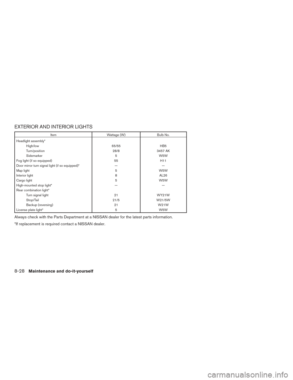
EXTERIOR AND INTERIOR LIGHTS
ItemWattage (W)Bulb No.
Headlight assembly* High/low 65/55HB5
Turn/position 28/83457 AK
Sidemarker 5W5W
Fog light (if so equipped) 55H11
Door mirror turn signal light (if so equipped)* ——
Map light 5W5W
Interior light 8AL26
Cargo light 5W5W
High-mounted stop light* ——
Rear combination light* Turn signal light 21WY21W
Stop/Tail 21/5W21/5W
Backup (reversing) 21W21W
License plate light* 5W5W
Always check with the Parts Department at a NISSAN dealer for the latest parts information.
*If replacement is required contact a NISSAN dealer.
8-28Maintenance and do-it-yourself
Page 340 of 384
1. Fog light (if so equipped)
2. Headlight assembly
3. Map light
4. Interior light
5. Stop/tail light
6. High-mounted stop light
7. Cargo light
8. License plate light
LDI2416
Maintenance and do-it-yourself8-29
Page 378 of 384
Event data recorders..............9-20
Exhaust gas (Carbon monoxide) .........5-2
Explanation of maintenance items ........8-2
Extendedstorageswitch ............8-23
F
Flashers (See hazard warning flasher switch) . .6-2
Flat tire .......................6-3
Floor mat positioning aid .............7-5
Fluid Brake fluid ..................8-13
Capacities and recommended
fuel/lubricants .................9-2
Continuously Variable Transmission (CVT)
fluid......................8-12
Engine coolant .................8-8
Engine oil ...................8-9
F.M.V.S.S. certification label ...........9-11
Foglightswitch .................2-28
Front air bag system
(See supplemental restraint system) ......1-49
Frontseats.....................1-2
Fuel Capacities and recommended
fuel/lubricants .................9-2
Fuel economy ................5-25
Fuel-filler door and cap ...........3-26
Fuel-filler door lock opener lever ......3-26
Fuel gauge ...................2-9
Fuel octane rating ...............9-5
Fuel recommendation .............9-4
Loose fuel cap warning ........2-6,3-27
Fuel gauge .....................2-9
Fuses.......................8-21 Fusiblelinks ...................8-21
G
Gascap .....................3-26
Gauge Engine coolant temperature gauge .....2-8
Fuel gauge ...................2-9
Odometer ...................2-5
Speedometer .................2-4
Tachometer ..................2-8
Trip computer ................2-10
Trip odometer .................2-5
General maintenance ...............8-2
Glovebox.....................2-34
Gloveboxlock..................2-34
Grocery hooks ..................2-37
H
Hands-free phone system,
Bluetooth®................4-76,4-91
Hazard warning flasher switch ..........6-2
Headlight and turn signal switch ........2-25
Headlight control switch ............2-25
Headlights ....................8-26
Head restraints ..................1-5
Heated seats ...................2-29
Heater Heater and air conditioner controls .....4-23
Heater operation ...............4-25
Hood release ...................3-24
Horn .......................2-29 I
Ignition switch ...................5-8
Ignition Switch Push-Button Ignition Switch ........5-10
Immobilizer system ......2-22,3-4,5-10,5-13
Important vehicle information label .......9-11
Increasing fuel economy .............5-25
Indicator
lights and audible reminders
(See warning/indicator lights and audible
reminders)....................2-13
Inside mirror ...................3-30
Instrument brightness control ..........2-27
Instrumentpanel...............0-6,2-2
Instrument panel dimmer switch ........2-27
Intelligent Key system Key operating range .............3-13
Key operation ................3-14
Mechanical key ................3-4
Remote keyless entry operation.......3-18
Troubleshooting guide ............3-23
Warning signals ...............3-23
Interior light ................2-40,2-41
iPod®Player ............... 4-65, 4-67
ISOFIX child restraints .............1-23
J
Jump starting ...............6-12,8-16
K
Key.........................3-2
Key fob battery replacement ..........8-24
10-3