2015 NISSAN TITAN seat memory
[x] Cancel search: seat memoryPage 186 of 457

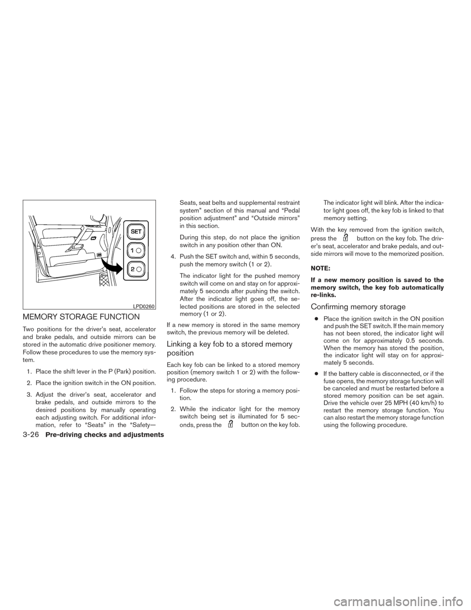
MEMORY STORAGE FUNCTION
Two positions for the driver’s seat, accelerator
and brake pedals, and outside mirrors can be
stored in the automatic drive positioner memory.
Follow these procedures to use the memory sys-
tem.1. Place the shift lever in the P (Park) position.
2. Place the ignition switch in the ON position.
3. Adjust the driver’s seat, accelerator and brake pedals, and outside mirrors to the
desired positions by manually operating
each adjusting switch. For additional infor-
mation, refer to “Seats” in the “Safety— Seats, seat belts and supplemental restraint
system” section of this manual and “Pedal
position adjustment” and “Outside mirrors”
in this section.
During this step, do not place the ignition
switch in any position other than ON.
4. Push the SET switch and, within 5 seconds, push the memory switch (1 or 2) .
The indicator light for the pushed memory
switch will come on and stay on for approxi-
mately 5 seconds after pushing the switch.
After the indicator light goes off, the se-
lected positions are stored in the selected
memory (1 or 2) .
If a new memory is stored in the same memory
switch, the previous memory will be deleted.
Linking a key fob to a stored memory
position
Each key fob can be linked to a stored memory
position (memory switch 1 or 2) with the follow-
ing procedure. 1. Follow the steps for storing a memory posi- tion.
2. While the indicator light for the memory switch being set is illuminated for 5 sec-
onds, press the
button on the key fob. The indicator light will blink. After the indica-
tor light goes off, the key fob is linked to that
memory setting.
With the key removed from the ignition switch,
press the
button on the key fob. The driv-
er’s seat, accelerator and brake pedals, and out-
side mirrors will move to the memorized position.
NOTE:
If a new memory position is saved to the
memory switch, the key fob automatically
re-links.
Confirming memory storage
● Place the ignition switch in the ON position
and push the SET switch. If the main memory
has not been stored, the indicator light will
come on for approximately 0.5 seconds.
When the memory has stored the position,
the indicator light will stay on for approxi-
mately 5 seconds.
● If the battery cable is disconnected, or if the
fuse opens, the memory storage function will
be canceled and must be restarted before a
stored memory position can be set again.
Drive the vehicle over 25 MPH (40 km/h) to
restart the memory storage function. You
can also restart the memory storage function
using the following procedure.
LPD0260
3-26Pre-driving checks and adjustments
Page 187 of 457

1. Connect the battery cable or replace thefuse.
2. Open and close the driver’s door more than two times with the ignition switch in the
LOCK position.
Once the memory storage function has been
restarted, you can store a memory position.
For additional information, refer to “Memory
storage function” in this section.
Selecting the memorized position
Set the shift lever to the P (Park) position, then: ● Within 45 seconds of opening the driver’s
door, push the memory switch (1 or 2) or
● Place the ignition switch in the ON position
and push the memory switch (1 or 2) .
The driver’s seat, accelerator and brake pedals,
and outside mirrors will move to the memorized
position with the indicator light blinking, and then
the light will stay on for approximately 5 seconds.
ENTRY/EXIT FUNCTION
This system is designed so that the driver’s seat
will automatically move when the shift lever is
placed in the P (Park) position. This allows the
driver to get into and out of the driver’s seat more
easily. The driver’s seat will slide backward:
● When the key is removed from the ignition
switch and the driver’s door is opened.
● When the driver’s door is opened with the
ignition switch placed in the LOCK position.
● When the ignition switch is turned from
ACC to LOCK with the driver’s door open.
The driver’s seat will return to the previous posi-
tion: ● When the key is inserted into the ignition
switch and the driver’s door is closed.
● When the driver’s door is closed with the
ignition switch placed in the LOCK position.
● When the ignition switch is turned from
ACC to ON while the shift lever is in the P
(Park) position.
The entry/exit function can be adjusted or can-
celed. See your NISSAN dealer.
Restarting the entry/exit function
If the battery cable is disconnected or if the fuse
opens, the entry/exit function will be disabled.
Drive the vehicle over 25 MPH (40 km/h) to
restart the entry/exit function. You can also restart
the entry/exit function using the following proce-
dure. 1. Connect the battery cable or replace the
fuse.
2. Open and close the driver’s door more than two times with the ignition switch in the
LOCK position.
The entry/exit function should now work properly.
SYSTEM OPERATION
The automatic drive positioner system will not
work or will stop operating under the following
conditions: ● When the vehicle speed is above 4 MPH
(7 km/h).
● When any of the memory switches are
pushed while the automatic drive positioner
is operating.
● When the adjusting switch for the driver’s
seat is turned on while the automatic drive
positioner is operating.
● When the seat has already been moved to
the memorized position.
● When no seat position is stored in the
memory switch.
● When the shift lever is moved from P (Park)
to any other position.
Pre-driving checks and adjustments3-27
Page 450 of 457

Immobilizer system............2-28,5-11
Important vehicle information label .......9-13
In-cabin microfilter ................8-20
Increasing fuel economy .............5-24
Indicator lights and audible reminders
(See warning/indicator lights and audible
reminders).................2-12,2-18
Informationdisplay............2-20,2-21
Inside automatic anti-glare mirror ........3-16
Instrument brightness control ..........2-36
Instrument panel ...............0-6,2-2
Instrument panel dimmer switch ........2-36
Interiorlight....................2-59
iPod®Player ...............4-58,4-61
ISOFIX child restraints .............1-27
J
Jump starting ................6-9,8-17
K
Key.........................3-2
Key fob battery replacement ..........8-26
Keyless entry Without Intelligent Key system
(See remote keyless entry system) ......3-7
Keys NISSAN Vehicle Immobilizer System keys . .3-2 L
Labels Air conditioner specification label .....9-14
C.M.V.S.S. certification label ........9-13
Emission control information label .....9-13
Engine serial number ............9-13
F.M.V.S.S. certification label .........9-13
Tire and Loading Information label .....9-14
Vehicle identification number (VIN) plate . .9-12
Warning labels (for SRS) ..........1-65
LATCH (Lower Anchors and Tethers for CHildren)
System ......................1-27
License plate Installing the license plate ..........9-14
Light Air bag warning light .........1-65,2-17
Brake light (See stop light) .........8-30
Bulbreplacement..............8-30
Charge warning light ............2-14
Consolelight.................2-60
Foglights...................8-28
Foglightswitch ...............2-37
Headlight and turn signal switch ......2-32
Headlight control switch ..........2-33
Headlights..................8-28
Interiorlight..................2-59
Lightbulbs..................8-28
Low tire pressure warning light .......2-15
Low windshield-washer fluid warning
light ..................2-17,2-26
Passenger air bag and status light .....1-59
Personal lights ................2-61
Security indicator light ............2-19 Warning/indicator lights and audible
reminders
...............2-12,2-18
Lights Maplights ..................2-61
Lock Child safety rear door lock ..........3-7
Door locks ...................3-3
Power door locks ...............3-4
Loose fuel cap warning .............2-26
Low fuel warning light .......2-15,2-17,2-26
Low tire pressure warning light .........2-15
Low windshield-washer fluid warning
light ....................2-17,2-26
Luggage (See vehicle loading information) . .9-15
M
Maintenance General maintenance .............8-2
Insidethevehicle...............8-3
Maintenance precautions ...........8-5
Outside the vehicle ..............8-2
Seat belt maintenance ............1-23
Under the hood and vehicle .........8-4
Maintenance
requirements ............8-2
Malfunction indicator light ............2-18
Manual front seat adjustment ...........1-3
Maplights ....................2-61
Mappocket....................2-49
Memory Seat ............3-25,3-26,3-27
Meters and gauges ................2-3
Instrument brightness control ........2-36
Mirror Automatic anti-glare inside mirror ......3-16
Outside mirrors ...............3-17
10-4