2015 NISSAN ROGUE SELECT key battery
[x] Cancel search: key batteryPage 117 of 322
2-42Instruments and controls
CAUTION
Do not use for extended periods of time
with the engine stopped. This could
result in a discharged battery.
MAP LIGHTS
Push the light lens to turn the map light on or off.
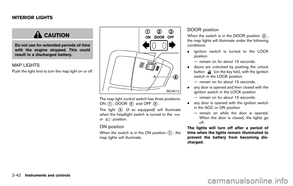
SIC3512
The map light control switch has three positions:
ON
*1, DOOR*2and OFF*3.
The light
*4(if so equipped) will illuminate
when the headlight switch is turned to the
orposition.
ON position
When the switch is in the ON position*1, the
map lights will illuminate.
DOOR position
When the switch is in the DOOR position*2,
the map lights will illuminate under the following
conditions:
. ignition switch is turned to the LOCK
position
— remain on for about 15 seconds.
. doors are unlocked by pushing the unlock
button
(on the key fob) , with the ignition
switch in the LOCK position
— remain on for about 15 seconds.
. any door is opened and then closed with the
ignition switch in the LOCK position
— remain on for about 15 seconds.
. any door is opened with the ignition switch
in the ACC or ON position
— remain on while the door is opened.
When the door is closed, the lights go
off.
The lights will turn off after a period of
time when the lights remain illuminated to
prevent the battery from becoming dis-
charged.
INTERIOR LIGHTS
Page 118 of 322
OFF position
When the switch is in the OFF position*3, the
map lights will not illuminate, regardless of the
condition.
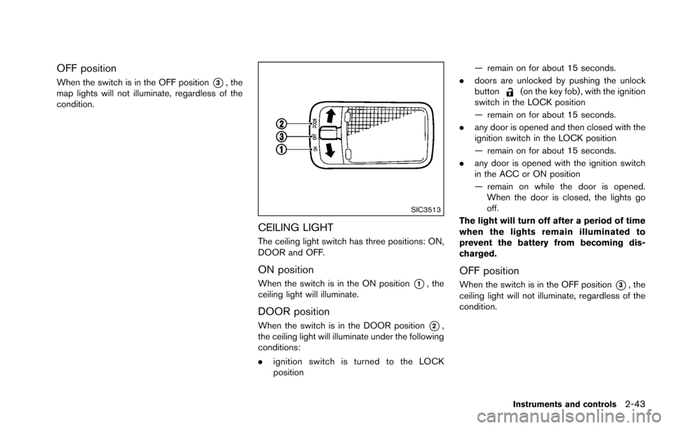
SIC3513
CEILING LIGHT
The ceiling light switch has three positions: ON,
DOOR and OFF.
ON position
When the switch is in the ON position*1, the
ceiling light will illuminate.
DOOR position
When the switch is in the DOOR position*2,
the ceiling light will illuminate under the following
conditions:
. ignition switch is turned to the LOCK
position — remain on for about 15 seconds.
. doors are unlocked by pushing the unlock
button
(on the key fob) , with the ignition
switch in the LOCK position
— remain on for about 15 seconds.
. any door is opened and then closed with the
ignition switch in the LOCK position
— remain on for about 15 seconds.
. any door is opened with the ignition switch
in the ACC or ON position
— remain on while the door is opened.
When the door is closed, the lights go
off.
The light will turn off after a period of time
when the lights remain illuminated to
prevent the battery from becoming dis-
charged.
OFF position
When the switch is in the OFF position*3, the
ceiling light will not illuminate, regardless of the
condition.
Instruments and controls2-43
Page 124 of 322
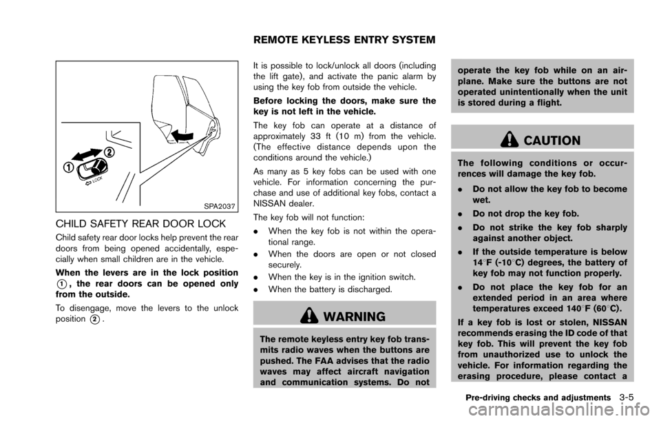
SPA2037
CHILD SAFETY REAR DOOR LOCK
Child safety rear door locks help prevent the rear
doors from being opened accidentally, espe-
cially when small children are in the vehicle.
When the levers are in the lock position
*1, the rear doors can be opened only
from the outside.
To disengage, move the levers to the unlock
position
*2. It is possible to lock/unlock all doors (including
the lift gate) , and activate the panic alarm by
using the key fob from outside the vehicle.
Before locking the doors, make sure the
key is not left in the vehicle.
The key fob can operate at a distance of
approximately 33 ft (10 m) from the vehicle.
(The effective distance depends upon the
conditions around the vehicle.)
As many as 5 key fobs can be used with one
vehicle. For information concerning the pur-
chase and use of additional key fobs, contact a
NISSAN dealer.
The key fob will not function:
.
When the key fob is not within the opera-
tional range.
. When the doors are open or not closed
securely.
. When the key is in the ignition switch.
. When the battery is discharged.WARNING
The remote keyless entry key fob trans-
mits radio waves when the buttons are
pushed. The FAA advises that the radio
waves may affect aircraft navigation
and communication systems. Do not operate the key fob while on an air-
plane. Make sure the buttons are not
operated unintentionally when the unit
is stored during a flight.
CAUTION
The following conditions or occur-
rences will damage the key fob.
.
Do not allow the key fob to become
wet.
. Do not drop the key fob.
. Do not strike the key fob sharply
against another object.
. If the outside temperature is below
148F (-108C) degrees, the battery of
key fob may not function properly.
. Do not place the key fob for an
extended period in an area where
temperatures exceed 1408F (608C) .
If a key fob is lost or stolen, NISSAN
recommends erasing the ID code of that
key fob. This will prevent the key fob
from unauthorized use to unlock the
vehicle. For information regarding the
erasing procedure, please contact a
Pre-driving checks and adjustments3-5
REMOTE KEYLESS ENTRY SYSTEM
Page 125 of 322
3-6Pre-driving checks and adjustments
NISSAN dealer.
For information regarding the replacement of a
battery, see “Battery replacement” (P.8-22).
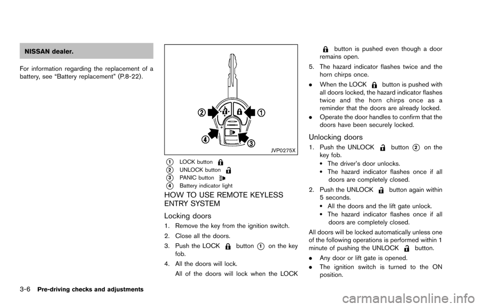
JVP0275X
*1LOCK button
*2UNLOCK button
*3PANIC button
*4Battery indicator light
HOW TO USE REMOTE KEYLESS
ENTRY SYSTEM
Locking doors
1. Remove the key from the ignition switch.
2. Close all the doors.
3. Push the LOCK
button*1on the key
fob.
4. All the doors will lock. All of the doors will lock when the LOCK
button is pushed even though a door
remains open.
5. The hazard indicator flashes twice and the horn chirps once.
. When the LOCK
button is pushed with
all doors locked, the hazard indicator flashes
twice and the horn chirps once as a
reminder that the doors are already locked.
. Operate the door handles to confirm that the
doors have been securely locked.
Unlocking doors
1. Push the UNLOCKbutton*2on the
key fob.
.The driver’s door unlocks..The hazard indicator flashes once if all doors are completely closed.
2. Push the UNLOCK
button again within
5 seconds.
.All the doors and the lift gate unlock..The hazard indicator flashes once if all doors are completely closed.
All doors will be locked automatically unless one
of the following operations is performed within 1
minute of pushing the UNLOCK
button.
. Any door or lift gate is opened.
. The ignition switch is turned to the ON
position.
Page 126 of 322
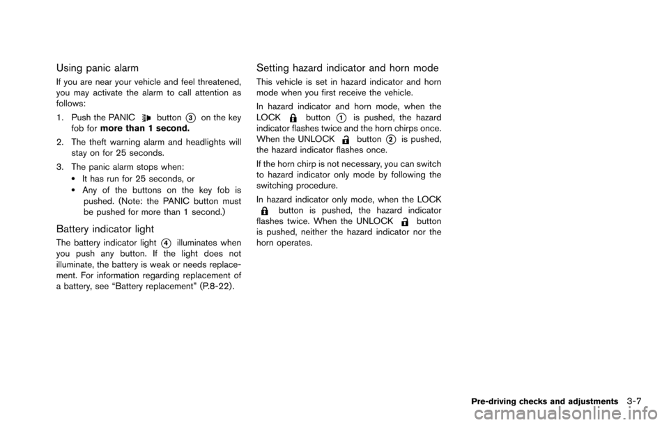
Using panic alarm
If you are near your vehicle and feel threatened,
you may activate the alarm to call attention as
follows:
1. Push the PANIC
button*3on the key
fob for more than 1 second.
2. The theft warning alarm and headlights will stay on for 25 seconds.
3. The panic alarm stops when:
.It has run for 25 seconds, or.Any of the buttons on the key fob is pushed. (Note: the PANIC button must
be pushed for more than 1 second.)
Battery indicator light
The battery indicator light*4illuminates when
you push any button. If the light does not
illuminate, the battery is weak or needs replace-
ment. For information regarding replacement of
a battery, see “Battery replacement” (P.8-22) .
Setting hazard indicator and horn mode
This vehicle is set in hazard indicator and horn
mode when you first receive the vehicle.
In hazard indicator and horn mode, when the
LOCK
button*1is pushed, the hazard
indicator flashes twice and the horn chirps once.
When the UNLOCK
button*2is pushed,
the hazard indicator flashes once.
If the horn chirp is not necessary, you can switch
to hazard indicator only mode by following the
switching procedure.
In hazard indicator only mode, when the LOCK
button is pushed, the hazard indicator
flashes twice. When the UNLOCKbutton
is pushed, neither the hazard indicator nor the
horn operates.
Pre-driving checks and adjustments3-7
Page 129 of 322
3-10Pre-driving checks and adjustments
WARNING
.Always be sure the lift gate has
been closed securely to prevent it
from opening while driving.
. Do not drive with the lift gate open.
This could allow dangerous exhaust
gases to be drawn into the vehicle.
See “Exhaust gas (carbon monox-
ide)” (P.5-2) of this manual.
. Make sure that all passengers have
their hands, etc. inside the vehicle
before closing the lift gate.
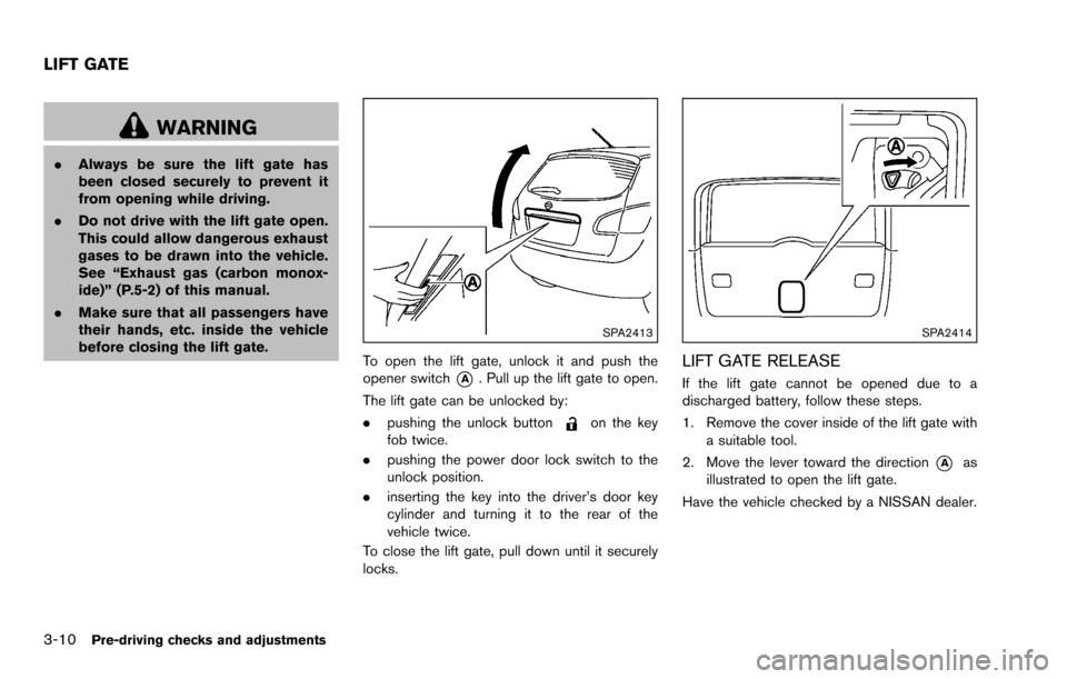
SPA2413
To open the lift gate, unlock it and push the
opener switch
*A. Pull up the lift gate to open.
The lift gate can be unlocked by:
. pushing the unlock button
on the key
fob twice.
. pushing the power door lock switch to the
unlock position.
. inserting the key into the driver’s door key
cylinder and turning it to the rear of the
vehicle twice.
To close the lift gate, pull down until it securely
locks.
SPA2414
LIFT GATE RELEASE
If the lift gate cannot be opened due to a
discharged battery, follow these steps.
1. Remove the cover inside of the lift gate with a suitable tool.
2. Move the lever toward the direction
*Aas
illustrated to open the lift gate.
Have the vehicle checked by a NISSAN dealer.
LIFT GATE
Page 188 of 322
5 Starting and driving
Precautions when starting and driving ................................ 5-2Exhaust gas (carbon monoxide) ...................................... 5-2
Three-way catalyst .............................................................. 5-3
Tire Pressure Monitoring System (TPMS) .................... 5-3
Avoiding collision and rollover ......................................... 5-5
On-pavement and off-road driving precautions .......... 5-6
Off-road recovery ................................................................ 5-6
Rapid air pressure loss ...................................................... 5-6
Drinking alcohol/drugs and driving ................................. 5-7
Driving safety precautions ................................................. 5-7
Ignition switch ........................................................................\
.... 5-9 Continuously Variable Transmission (CVT) ................... 5-9
Key positions ..................................................................... 5-10
Before starting the engine ................................................... 5-10
Starting the engine ................................................................ 5-11
Driving the vehicle ................................................................. 5-12 Continuously Variable Transmission (CVT) ................ 5-12
Parking brake ........................................................................\
.. 5-16
Cruise control (if so equipped) .......................................... 5-17 Precautions on cruise control ....................................... 5-17
Cruise control operations ............................................... 5-18 Break-in schedule ................................................................. 5-19
Fuel efficient driving tips ..................................................... 5-19
Increasing fuel economy ...................................................... 5-20
All-Wheel Drive (AWD) (if so equipped) ........................ 5-20
All-Wheel Drive (AWD) lock switch operations ..... 5-21
AWD warning light ........................................................ 5-22
Parking/parking on hills ........................................................ 5-23
Electric power steering system ......................................... 5-24
Brake system ........................................................................\
.. 5-25 Braking precautions ...................................................... 5-25
Parking brake break-in .................................................. 5-25
Anti-lock Braking System (ABS) ............................... 5-25
Vehicle Dynamic Control (VDC) system ......................... 5-27
Cold weather driving ............................................................ 5-28 Freeing a frozen door lock ........................................... 5-28
Anti-freeze ........................................................................\
5-28
Battery ........................................................................\
....... 5-28
Draining of coolant water ............................................. 5-28
Tire equipment ................................................................ 5-29
Special winter equipment ............................................ 5-29
Driving on snow or ice ................................................. 5-29
Page 203 of 322
5-16Starting and driving
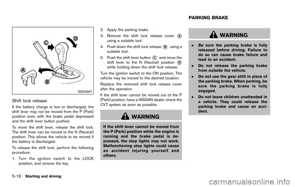
SSD0667
Shift lock release
If the battery charge is low or discharged, the
shift lever may not be moved from the P (Park)
position even with the brake pedal depressed
and the shift lever button pushed.
To move the shift lever, release the shift lock.
The shift lever can be moved to the N (Neutral)
position. This allows the vehicle to be moved if
the battery is discharged.
To release the shift lock, perform the following
procedure:
1. Turn the ignition switch to the LOCKposition, and remove the key. 2. Apply the parking brake.
3. Remove the shift lock release cover
*Ausing a suitable tool.
4. Push down the shift lock release
*Busing a
suitable tool.
5. Push the shift lever button
*Cand move the
shift lever to the N (Neutral) position
*Dwhile holding down the shift lock release.
Turn the ignition switch to the ON position. The
vehicle may be moved to the desired location.
Replace the removed shift lock release cover
after the operation.
If the shift lever cannot be moved out of the P
(Park) position, have a NISSAN dealer check the
CVT system as soon as possible.
WARNING
If the shift lever cannot be moved from
the P (Park) position while the engine is
running and the brake pedal is de-
pressed, the stop lights may not work.
Malfunctioning stop lights could cause
an accident injuring yourself and
others.
WARNING
. Be sure the parking brake is fully
released before driving. Failure to
do so can cause brake failure and
lead to an accident.
. Do not release the parking brake
from outside the vehicle.
. Do not use the gear shift in place of
the parking brake. When parking, be
sure the parking brake is fully
engaged.
. Do not leave children unattended in
a vehicle. They could release the
parking brake and cause an acci-
dent.
PARKING BRAKE