Page 227 of 424
The current play pattern of the CD is displayed on
the screen unless no pattern is applied.
Page 228 of 424
CAUTION
●To avoid damage and loss of function
when using a USB device, note the fol-
lowing precautions.
● Do not force the USB device into the
USB port. Inserting the USB device
tilted or up-side-down into the port may
damage the port. Make sure that the
USB device is connected correctly into
the USB port.
● Do not grab the USB port cover (if so
equipped) when pulling the USB device
out of the port. This could damage the
port and the cover.
● Do not leave the USB cable in a place
where it can be pulled unintentionally.
Pulling the cable may damage the port.
Refer to your device manufacturer’s owner infor-
mation regarding the proper use and care of the
device.
There are two USB connection ports available in
the vehicle. One is located in the media pocket on
the center console near the cupholders, the other
on the back of the rear center console facing the
rear seats. Insert the USB device into the con-
nection port. When a compatible storage device is plugged
into the connection port, compatible audio files
on the storage device can be played through the
vehicle’s audio system.
Audio file operation
MEDIA button
Place the ignition switch in the ON or ACC
position and press the MEDIA button to switch to
the USB input mode. If a CD is playing or another
audio source is plugged in through the AUX IN
jack located in the center console, the MEDIA
button toggles between the three sources.
Play information
Information about the audio files being played
can be displayed on the display screen of the
vehicle’s audio system. Depending on how the
audio files are encoded, information such as
Folder, Song and Artist will be displayed.
The track number and number of total tracks in
the folder are displayed on the screen as well.
Page 229 of 424
OFF: No random play pattern is applied. The
indicator on the display will turn off.
The current play pattern of the USB device is
displayed on the screen unless no pattern is
applied.
RPT (repeat) button
When the RPT (repeat) button is pressed while
an audio file on the USB device is playing, the
play pattern can be changed as follows:
1 Folder Repeat→1 Track Repeat →OFF
1 Track Repeat: the current track will be re-
peated.
1 Folder Repeat: the current folder will be re-
peated.
OFF: No repeat play pattern is applied. The indi-
cator on the display will turn off.
The current play pattern of the USB device is
displayed on the screen unless no pattern is
applied. TUNE/SCROLL knob
If there are multiple folders with audio files on the
USB device, turn the TUNE/SCROLL knob to
change folders. Turn the knob to the left to skip
back a folder. Turn the knob to the right to skip
ahead a folder. If there is only one folder of audio
files on the USB device, turning the
TUNE/SCROLL knob in either direction will re-
turn to the first track on the USB device.
iPod®* PLAYER OPERATION
WITHOUT NAVIGATION SYSTEM (if
so equipped)
Connecting iPod®
Page 230 of 424
CAUTION
●Do not force the USB device into the
USB port. Inserting the USB device
tilted or up-side-down into the port may
damage the port. Make sure that the
USB device is connected correctly into
the USB port.
● Do not grab the USB port cover (if so
equipped) when pulling the USB device
out of the port. This could damage the
port and the cover.
● Do not leave the USB cable in a place
where it can be pulled unintentionally.
Pulling the cable may damage the port.
Refer to your device manufacturer’s owner infor-
mation regarding the proper use and care of the
device.
To connect an iPod® to the vehicle so that the
iPod® can be controlled with the audio system
controls and display screen, use the USB con-
nection port located on the center console near
the cupholders, or the other on the back of the
rear center console facing the rear seats. Con-
nect the iPod®-specific end of the cable to the
iPod® and the USB end of the cable to the USB
connection port on the vehicle. If your iPod®
supports charging via a USB connection, its bat- tery will be charged while connected to the ve-
hicle with the ignition switch in the ACC or ON
position.
While connected to the vehicle, the iPod® can
only be operated by the vehicle audio controls.
To disconnect the iPod® from the vehicle, re-
move the USB end of the cable from the USB
connection port on the vehicle, then remove the
cable from the iPod®.
* iPod® is a trademark of Apple Inc., registered in
the U.S. and other countries.
Compatibility
The following models are compatible:
● iPod® Classic - 5th Generation (firmware
version 1.3.0 or later)
● iPod® Classic - 6th Generation (firmware
version 2.0.1 or later)
● iPod® Classic - 7th Generation (firmware
version 2.0.4 or later)
● iPod® nano - 1st generation (firmware ver-
sion 1.3.1 or later)
● iPod® nano - 2nd generation (firmware ver-
sion 1.1.3 or later)
● iPod® nano - 3rd generation (firmware ver-
sion 1.1.3 or later) ●
iPod® nano - 4th generation (firmware ver-
sion 1.0.4 or later)
● iPod® nano - 5th generation (firmware ver-
sion 1.0.2 or later)
● iPod® nano - 6th generation (firmware ver-
sion 1.1 or later)
● iPod® Touch - 2nd generation (firmware
version 4.2.1 or later)
● iPod® Touch - 3rd generation (firmware ver-
sion 5.1 or later) (minimum iOS 5.0 required
for smartphone integration)
● iPod® Touch - 4th generation (firmware ver-
sion 5.1 or later) (minimum iOS 5.0 required
for smartphone integration)
● iPhone® 3G (firmware version 4.2.1 or later)
● iPhone® 3GS (firmware version 5.1 or later)
(minimum iOS 5.0 required for smartphone
integration)
● iPhone® 4 (firmware version 5.1 or later)
(minimum iOS 5.0 required for smartphone
integration)
● iPhone® 4S (firmware version 5.1 or later)
(minimum iOS 5.0 required for smartphone
integration)
Display screen, heater, air conditioner, audio and phone systems4-45
Page 244 of 424
RECEIVING A CALL
When a call is received by the phone connected
to the vehicle’s Bluetooth® Hands-Free Phone
System, the call information is displayed on either
the vehicle information display or both the vehicle
information display and he control panel display.
Press the
Page 253 of 424
Additional information:● The TPMS does not monitor the tire
pressure of the spare tire.
● The TPMS will activate only when the vehicle
is driven at speeds above 16 MPH
(25 km/h). Also, this system may not detect a
sudden drop in tire pressure (for example a
flat tire while driving) .
● The low tire pressure warning light does not
automatically turn off when the tire pressure
is adjusted. After the tire is inflated to the
recommended pressure, the vehicle must be
driven at speeds above 16 MPH (25 km/h)
to activate the TPMS and turn off the low tire
pressure warning light. Use a tire pressure
gauge to check the tire pressure.
● The “Tire Pressure Low Add Air” warning
appears in the vehicle information display
when the low tire pressure warning light is
illuminated and low tire pressure is detected.
The “Tire Pressure Low Add Air” warning
turns off when the low tire pressure warning
light turns off.
● The “Tire Pressure Low Add Air” warning
appears each time the ignition switch is
placed in the ON position as long as the low
tire pressure warning light remains illumi-
nated. ●
The “Tire Pressure Low Add Air” warning
does not appear if the low tire pressure
warning light illuminates to indicate a TPMS
malfunction.
● Tire pressure rises and falls depending on
the heat caused by the vehicle’s operation
and the outside temperature. Low outside
temperature can lower the temperature of
the air inside the tire which can cause a
lower tire inflation pressure. This may cause
the low tire pressure warning light to illumi-
nate. If the warning light illuminates, check
the tire pressure for all four tires.
● The Tire and Loading Information label (also
referred to as the vehicle placard or tire
inflation pressure label) is located in the
driver’s door opening.
● You can also check the pressure of all tires
(except the spare tire) on the vehicle infor-
mation display screen. The order of the tire
pressure figures displayed on the screen
corresponds with the actual order of the tire
position.
For additional information, refer to “Low tire pres-
sure warning light” in the “Instruments and con-
trols” section and “Tire Pressure Monitoring Sys-
tem (TPMS)” in the “In case of emergency”
section of this manual.
Page 272 of 424
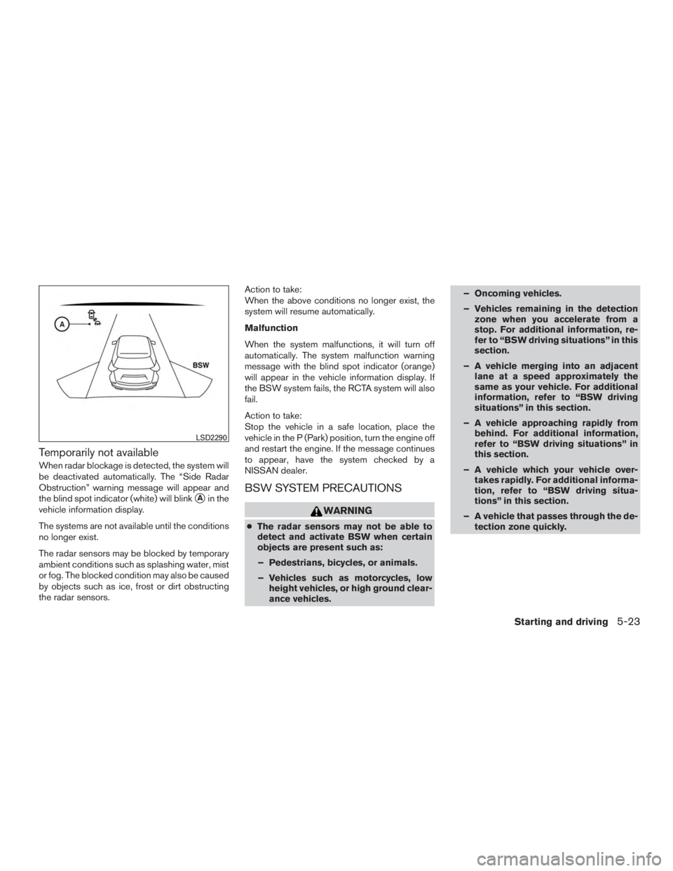
Temporarily not available
When radar blockage is detected, the system will
be deactivated automatically. The “Side Radar
Obstruction” warning message will appear and
the blind spot indicator (white) will blink
�Ain the
vehicle information display.
The systems are not available until the conditions
no longer exist.
The radar sensors may be blocked by temporary
ambient conditions such as splashing water, mist
or fog. The blocked condition may also be caused
by objects such as ice, frost or dirt obstructing
the radar sensors. Action to take:
When the above conditions no longer exist, the
system will resume automatically.
Malfunction
When the system malfunctions, it will turn off
automatically. The system malfunction warning
message with the blind spot indicator (orange)
will appear in the vehicle information display. If
the BSW system fails, the RCTA system will also
fail.
Action to take:
Stop the vehicle in a safe location, place the
vehicle in the P (Park) position, turn the engine off
and restart the engine. If the message continues
to appear, have the system checked by a
NISSAN dealer.BSW SYSTEM PRECAUTIONS
Page 273 of 424
●The radar sensors detection zone is de-
signed based on a standard lane width.
When driving in a wider lane, the radar
sensors may not detect vehicles in an
adjacent lane. When driving in a narrow
lane, the radar sensors may detect ve-
hicles driving two lanes away.
● The radar sensors are designed to ig-
nore most stationary objects, however
objects such as guardrails, walls, foli-
age and parked vehicles may occasion-
ally be detected. The system malfunc-
tion warning message with the blind
spot indicator (orange) will appear in
the vehicle information display. This is a
normal driving condition.
● Severe weather or road spray condi-
tions may reduce the ability of the radar
to detect other vehicles.
● Excessive noise (e.g. audio system vol-
ume, open vehicle window) will inter-
fere with the chime sound, and it may
not be heard.
BSW DRIVING SITUATIONS
Another vehicle approaching from
behind
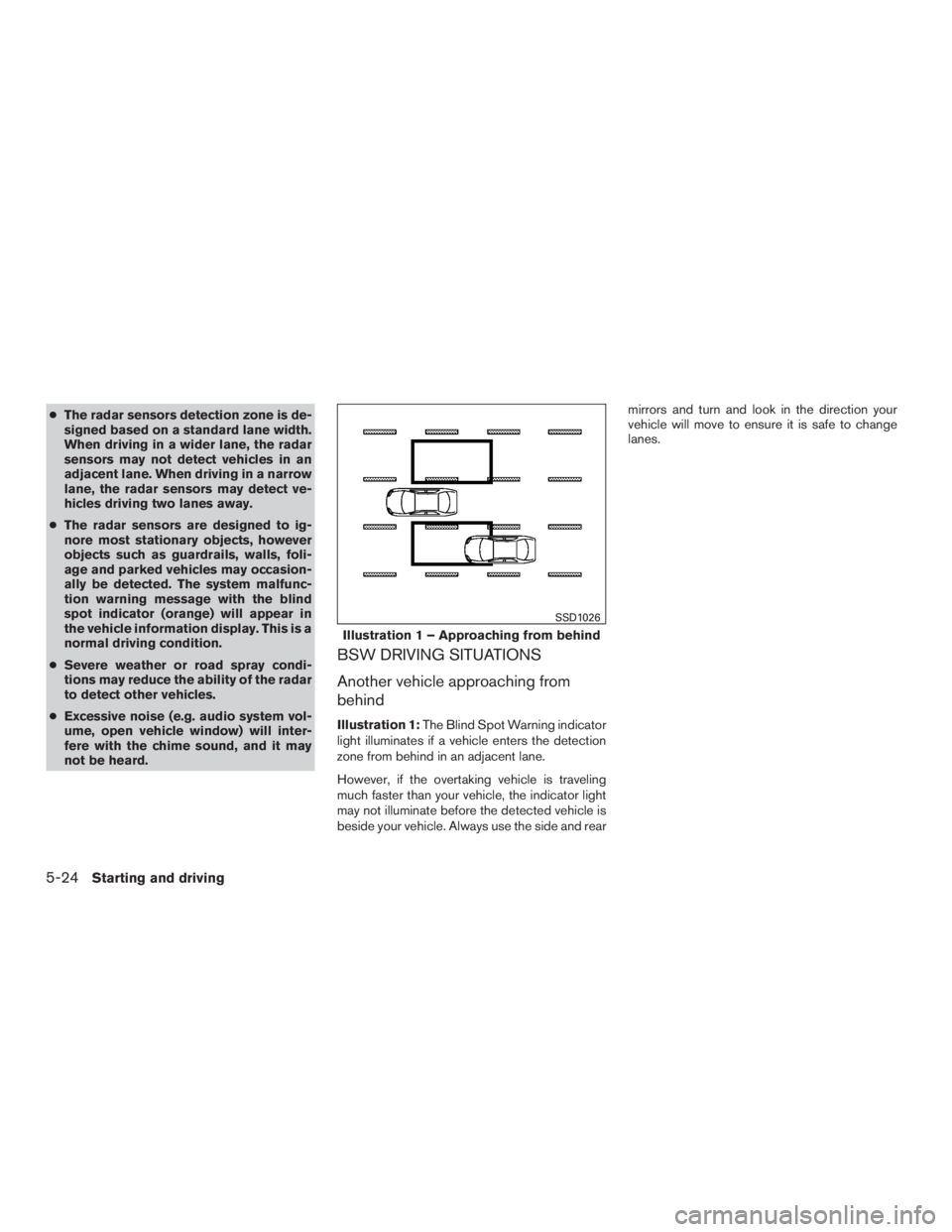
Illustration 1: The Blind Spot Warning indicator
light illuminates if a vehicle enters the detection
zone from behind in an adjacent lane.
However, if the overtaking vehicle is traveling
much faster than your vehicle, the indicator light
may not illuminate before the detected vehicle is
beside your vehicle. Always use the side and rear mirrors and turn and look in the direction your
vehicle will move to ensure it is safe to change
lanes.