Page 74 of 293

2 Instruments and controls
Instrument panel...................................2-2
Meters and gauges ................................2-3
Speedometer and odometer .....................2-3
Tachometer ....................................2-4
Fuel gauge ....................................2-5
Trip computer ..................................2-5
Warning/indicator lights and audible reminders .......2-7
Checking bulbs ................................2-7
Warning lights .................................2-8
Indicator lights ................................ 2-10
Audible reminders ............................. 2-12
Security systems ................................. 2-13
NISSAN vehicle immobilizer system .............2-13
Windshield wiper and washer switch ...............2-14
Switch operation .............................. 2-14
Rear window wiper and washer switch ..............2-16
Rear window defroster switch ......................2-16
Headlight and turn signal switch ....................2-17
Headlight control switch ........................ 2-17Daytime running light system
....................2-18
Instrument brightness control ...................2-18
Turn signal switch ............................. 2-19
Front fog lights (if so equipped) .................2-19
Horn ............................................ 2-20
Vehicle Dynamic Control (VDC) off switch ...........2-20
Power outlet ..................................... 2-21
Storage ......................................... 2-21
Map pockets .................................. 2-21
Storage trays ................................. 2-22
Cup holders .................................. 2-22
Soft bottle holder .............................. 2-23
Glove box .................................... 2-23
Tonneau cover (if so equipped) ..................2-23
Windows ........................................ 2-24
Power windows (if so equipped) ................2-24
Manual windows (if so equipped) ................2-26
Interior light ...................................... 2-27
Luggage
compartment light ........................ 2-27
Page 75 of 293

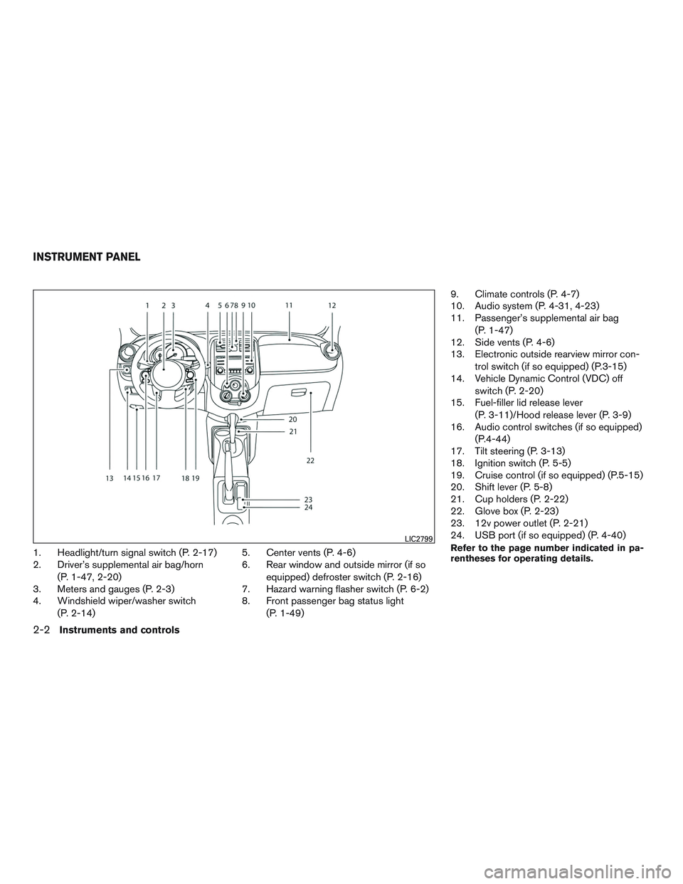
1. Headlight/turn signal switch (P. 2-17)
2. Driver’s supplemental air bag/horn(P. 1-47, 2-20)
3. Meters and gauges (P. 2-3)
4. Windshield wiper/washer switch
(P. 2-14) 5. Center vents (P. 4-6)
6. Rear window and outside mirror (if so
equipped) defroster switch (P. 2-16)
7. Hazard warning flasher switch (P. 6-2)
8. Front passenger bag status light
(P. 1-49) 9. Climate controls (P. 4-7)
10. Audio system (P. 4-31, 4-23)
11. Passenger’s supplemental air bag
(P. 1-47)
12. Side vents (P. 4-6)
13. Electronic outside rearview mirror con-
trol switch (if so equipped) (P.3-15)
14. Vehicle Dynamic Control (VDC) off
switch (P. 2-20)
15. Fuel-filler lid release lever
(P. 3-11)/Hood release lever (P. 3-9)
16. Audio control switches (if so equipped)
(P.4-44)
17. Tilt steering (P. 3-13)
18. Ignition switch (P. 5-5)
19. Cruise control (if so equipped) (P.5-15)
20. Shift lever (P. 5-8)
21. Cup holders (P. 2-22)
22. Glove box (P. 2-23)
23. 12v power outlet (P. 2-21)
24. USB port (if so equipped) (P. 4-40)Refer to the page number indicated in pa-
rentheses for operating details.LIC2799
INSTRUMENT PANEL
2-2Instruments and controls
Page 78 of 293

FUEL GAUGE
The gauge indicates�Atheapproximate fuel
level in the tank when the ignition switch is placed
in the ON position.
When one segment remains on the digital fuel
gauge, only one segment will blink. When no
segments remain on the digital fuel gauge, the
fuel gauge symbol and the scale will blink.
Refill the fuel tank before the gauge regis-
ters E (Empty) .
The
indicates that the fuel-filler door is
located on the driver’s side of the vehicle.
CAUTION
● If the vehicle runs out of fuel, thecheck engine light may come on. Refuel
as soon as possible. After a few driving
trips, the
light should turn off. If
the light remains on after a few driving
trips, have the vehicle inspected by a
NISSAN dealer.
● For additional information, refer to
“Malfunction Indicator Light (MIL)” in
this section.
TRIP COMPUTER
When the ignition switch is placed in the ON
position, modes of the trip computer can be
selected by pushing the trip computer
change/reset button
�Aon the instrument panel
located near the speedometer. The following
modes can be selected in the display
�B:
● Instant fuel consumption
● Average fuel consumption
● Distance to empty
LIC2167LIC2168
Instruments and controls2-5
Page 90 of 293
To defrost the rear window glass, start the engine
and push the rear window defroster switch on.
The rear window defroster indicator light on the
switch comes on. Push the switch again to turn
the defroster off.
The rear window defroster automatically turns off
after approximately 15 minutes.
CAUTION
When cleaning the inner side of the rear
window, be careful not to scratch or dam-
age the rear window defroster.
HEADLIGHT CONTROL SWITCH
Lighting
�1When turning the switch to theposi-
tion, the front parking, tail, license plate and
instrument panel lights come on.
�2When turning the switch to theposi-
tion, the headlights come on and all the other
lights remain on.
CAUTION
Use the headlights with the engine run-
ning to avoid discharging the vehicle
battery.
Type B (if so equipped)
LIC2110LIC2127
HEADLIGHT AND TURN SIGNAL
SWITCH
Instruments and controls2-17
Page 91 of 293

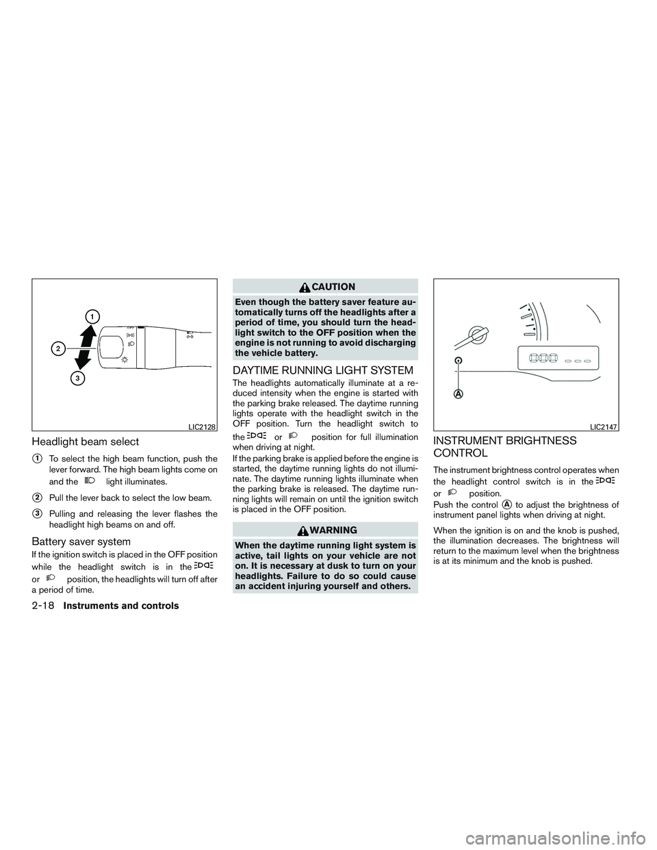
Headlight beam select
�1To select the high beam function, push the
lever forward. The high beam lights come on
and the
light illuminates.
�2Pull the lever back to select the low beam.
�3Pulling and releasing the lever flashes the
headlight high beams on and off.
Battery saver system
If the ignition switch is placed in the OFF position
while the headlight switch is in the
orposition, the headlights will turn off after
a period of time.
CAUTION
Even though the battery saver feature au-
tomatically turns off the headlights after a
period of time, you should turn the head-
light switch to the OFF position when the
engine is not running to avoid discharging
the vehicle battery.
DAYTIME RUNNING LIGHT SYSTEM
The headlights automatically illuminate at a re-
duced intensity when the engine is started with
the parking brake released. The daytime running
lights operate with the headlight switch in the
OFF position. Turn the headlight switch to
the
orposition for full illumination
when driving at night.
If the parking brake is applied before the engine is
started, the daytime running lights do not illumi-
nate. The daytime running lights illuminate when
the parking brake is released. The daytime run-
ning lights will remain on until the ignition switch
is placed in the OFF position.
WARNING
When the daytime running light system is
active, tail lights on your vehicle are not
on. It is necessary at dusk to turn on your
headlights. Failure to do so could cause
an accident injuring yourself and others.
INSTRUMENT BRIGHTNESS
CONTROL
The instrument brightness control operates when
the headlight control switch is in the
orposition.
Push the control
�Ato adjust the brightness of
instrument panel lights when driving at night.
When the ignition is on and the knob is pushed,
the illumination decreases. The brightness will
return to the maximum level when the brightness
is at its minimum and the knob is pushed.
LIC2128LIC2147
2-18Instruments and controls
Page 98 of 293
1. Window lock button
2. Power door lock switch
3. Front passenger’s side window switch
4. Right rear passenger’s window switch
5. Left rear passenger’s window switch
6. Driver’s side automatic switch
Driver’s side power window switch
The driver’s side control panel is equipped with
switches to open or close the front and rear
passenger windows.
To open a window, push the switch and hold it
down. To close a window, pull the switch and
hold it up. To stop the opening or closing function
at any time, simply release the switch.
Front passenger’s power window
switch
The passenger’s window switch operates only
the corresponding passenger’s window. To open
the window, push the switch and hold it down
�1.
To close the window, pull the switch up
�2.
WIC0872LIC0718
Instruments and controls2-25
Page 110 of 293
1. Pull the hood lock release handle�1located
below the instrument panel until the hood
springs up slightly.
2. Locate the lever
�2in between the hood and
grille and push the lever sideways with your
fingertips.
3. Raise the hood
�3.
4. Remove the support rod
�4and insert it into
the slot
�5. Hold the coated parts
�Awhen removing or
resetting the support rod. Avoid direct con-
tact with the metal parts, as they may be
hot immediately after the engine has been
stopped.
When closing the hood, return the support rod to
its original position, lower the hood to approxi-
mately 30 cm (12 in) above the latch and release
it. This allows proper engagement of the hood
latch.
WARNING
● Make sure the hood is completely
closed and latched before driving. Fail-
ure to do so could cause the hood to fly
open and result in an accident.
● If you see steam or smoke coming from
the engine compartment, to avoid injury
do not open the hood.
LPD2023
HOOD
Pre-driving checks and adjustments3-9
Page 112 of 293

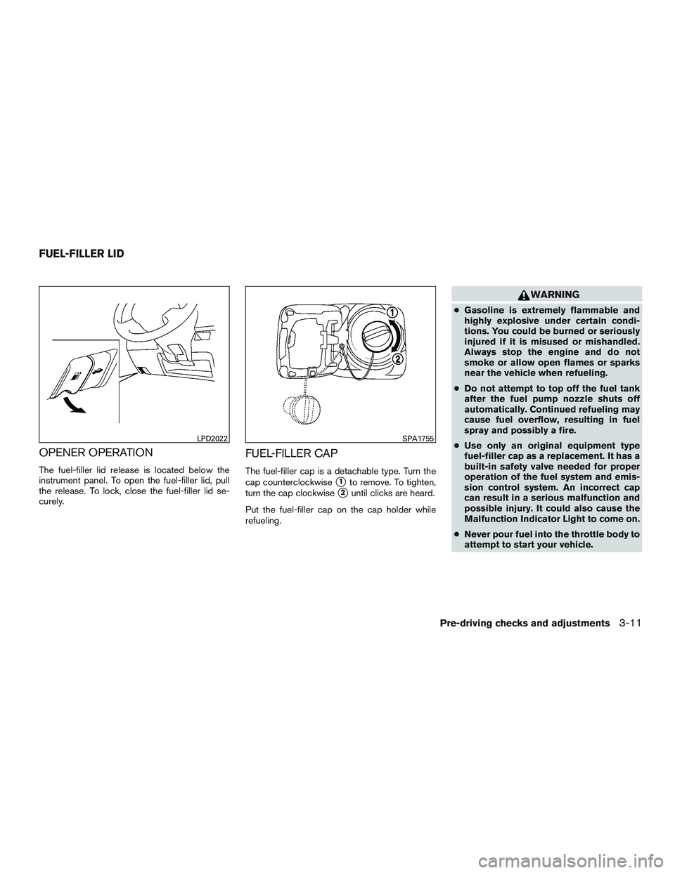
OPENER OPERATION
The fuel-filler lid release is located below the
instrument panel. To open the fuel-filler lid, pull
the release. To lock, close the fuel-filler lid se-
curely.
FUEL-FILLER CAP
The fuel-filler cap is a detachable type. Turn the
cap counterclockwise
�1to remove. To tighten,
turn the cap clockwise
�2until clicks are heard.
Put the fuel-filler cap on the cap holder while
refueling.
WARNING
● Gasoline is extremely flammable and
highly explosive under certain condi-
tions. You could be burned or seriously
injured if it is misused or mishandled.
Always stop the engine and do not
smoke or allow open flames or sparks
near the vehicle when refueling.
● Do not attempt to top off the fuel tank
after the fuel pump nozzle shuts off
automatically. Continued refueling may
cause fuel overflow, resulting in fuel
spray and possibly a fire.
● Use only an original equipment type
fuel-filler cap as a replacement. It has a
built-in safety valve needed for proper
operation of the fuel system and emis-
sion control system. An incorrect cap
can result in a serious malfunction and
possible injury. It could also cause the
Malfunction Indicator Light to come on.
● Never pour fuel into the throttle body to
attempt to start your vehicle.
LPD2022SPA1755
FUEL-FILLER LID
Pre-driving checks and adjustments3-11