Page 166 of 412
25. Parking brake release warning
This warning appears when the vehicle speed is
above 4 MPH (7km/h) and the parking brake is
applied.
TRIP COMPUTER
Switches for the trip computer are located on the
left side of the combination meter panel. To op-
erate the trip computer, push the following
switches:
�Aswitch
�BswitchWhen the power switch is pushed to the ON
position, modes of the trip computer can be
selected by pushing the
switch�A.
Each time the
switch�Ais pushed, the
display will change as follows:
Charging time →Energy economy →State of
charge →Average speed →Driving distance and
elapsed time→ Setting→Warning check
Instruments and controls2-27
Page 169 of 412
 the vehicle has been driven since the
last reset. The distance can be reset by push")
Driving distance and elapsed time
Driving distance:
The driving distance mode shows the total distance
(miles or km) the vehicle has been driven since the
last reset. The distance can be reset by pushing the
switch�Bfor longer than 1 second. (The
elapsed time is also reset at the same time.)
Elapsed time:
The elapsed time mode shows the time since the
last reset. The displayed time can be reset by push-
ing the
switch�Bfor longer than 1 second.
(The driving distance is also reset at the same
time.)
Settings
Settings cannot be accessed while driving.
The message, “settings can only be ac-
cessed when stationary” is also displayed
on the vehicle information display. The
switch�Aandswitch�Bare
used in the settings mode.
Push the
switch�Bto scroll through the
menus.
Push the
switch�Ato select a menu.
Skip:
Push the
switch�Ato move to the warning
check mode.
Push the
switch�Bto select other menus.
Clock:
The clock can be adjusted in this menu.
• Back Select this submenu to return to the top page
of the settings mode.
• Set Clock Adjust the time (hour and minute) of the clock.
For models without navigation system, the day of
the week can also be set to use it for the climate
control timer setting. (See “Climate Ctrl. timer” in
the “Display screen, heater, air conditioner, audio
and phone systems” section.)
• 24/12Hr (24 hours or 12 hours) Select either the 24-hour clock display or the
12-hour display.
2-30Instruments and controls
Page 171 of 412
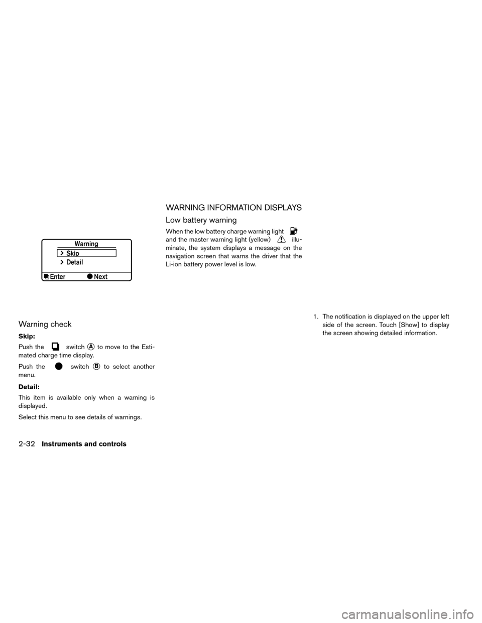
Warning check
Skip:
Push the
switch�Ato move to the Esti-
mated charge time display.
Push the
switch�Bto select another
menu.
Detail:
This item is available only when a warning is
displayed.
Select this menu to see details of warnings.
WARNING INFORMATION DISPLAYS
Low battery warning
When the low battery charge warning light
and the master warning light (yellow)illu-
minate, the system displays a message on the
navigation screen that warns the driver that the
Li-ion battery power level is low.
1. The notification is displayed on the upper leftside of the screen. Touch [Show] to display
the screen showing detailed information.
2-32Instruments and controls
Page 172 of 412

2. The system displays a message screen andannounces the contents of the message to
warn that the Li-ion battery power level is low.
Check the message displayed on the screen.
Touch [Nearby Charging Station] to search all
charging stations that are located around the
current vehicle position.
3. Touch [BACK] or push the MAPbutton to
return to the vehicle location screen.
NOTE:
• The low battery warning can be set to off.
See LEAF Navigation System Owner’s
Manual.
• When the battery power level is low, the
system automatically obtains charging
station information.
Limited power warning
When the Li-ion battery power level is extremely
low or the Li-ion battery malfunctions, the power
limitation indicator
and the master warning
light (yellow)
illuminate in the meter and the
system displays a message on the navigation
screen in order to inform the driver that power
output is restricted. 1. The notification is displayed on the upper left
side of the screen. Touch [Show] to display
the screen showing detailed information.
Instruments and controls2-33
Page 173 of 412

2. The system displays a message screen andannounces the contents of the message to
warn that power output is restricted and in-
form the driver of the reason for this occur-
rence and what action is to be taken.
INDICATORS FOR MAINTENANCE
1. Tire replacement indicator
This indicator appears when the customer set
distance comes for replacing tires. You can set or
reset the distance for replacing tires. (See “Trip
computer” in this section.)WARNING
The tire replacement indicator is not a
substitute for regular tire checks, includ-
ing tire pressure checks. See “Changing wheels and tires” in the “Maintenance
and do-it-yourself” section. Many factors
including tire inflation, alignment, driving
habits and road conditions affect tire
wear and when tires should be replaced.
Setting the tire replacement indicator for
a certain driving distance does not mean
your tires will last that long. Use the tire
replacement indicator as a guide only
and always perform regular tire checks.
Failure to perform regular tire checks,
including tire pressure checks could re-
sult in tire failure. Serious vehicle dam-
age could occur and may lead to a colli-
sion, which could result in serious
personal injury or death.
2. 3. 4. “Other” indicator
These indicators appears when the customer set
distance comes for checking or replacing main-
tenance items other than the tires. Other mainte-
nance items can include such things as the tire
rotation. You can set or reset the distance for
checking or replacing the items. (See “Trip com-
puter” in this section.) For scheduled mainte-
nance items and intervals, see your NISSAN Ser-
vice and Maintenance Guide.
2-34Instruments and controls
Page 177 of 412

Security indicator light
The security indicator light is located on the me-
ter panel. It indicates the status of the NISSAN
Vehicle Immobilizer System.
The light blinks after the power switch was in the
ACC or OFF position. This function indicates the
security systems equipped on the vehicle are
operational.
If the NISSAN Vehicle Immobilizer System is mal-
functioning, this light will remain on while the
power switch is in the ON position.If the light still remains on and/or the
power switch cannot be placed in the
READY to drive position, see a NISSAN
certified LEAF dealer for a NISSAN Vehicle
Immobilizer System service as soon as
possible. Please bring all registered keys
that you have when visiting a NISSAN cer-
tified LEAF dealer for service.
WARNING
In freezing temperatures the washer so-
lution may freeze on the windshield and
obscure your vision which may lead to an
accident. Warm the windshield with the
defroster before you wash the wind-
shield.
CAUTION
• Do not operate the washer continu- ously for more than 30 seconds.
• Do not operate the washer if the reser- voir tank is empty.
• Do not fill the window washer reservoir tank with washer fluid concentrates at
full strength. Some methyl alcohol
based washer fluid concentrates may
permanently stain the grille if spilled
while filling the window washer reser-
voir tank.
• Pre-mix washer fluid concentrates with water to the manufacturer’s rec-
ommended levels before pouring the
fluid into the window washer reservoir
tank. Do not use the window washer
reservoir tank to mix the washer fluid
concentrate and water.
WINDSHIELD WIPER AND WASHER
SWITCH
2-38Instruments and controls
Page 179 of 412

WARNING
In freezing temperatures the washer so-
lution may freeze on the rear window
glass and obscure your vision. Warm the
rear window with the defroster before
you wash the rear window.
CAUTION
• Do not operate the washer continu- ously for more than 30 seconds.
• Do not operate the washer if the reser- voir tank is empty.
• Do not fill the window washer reservoir tank with washer fluid concentrates at
full strength. Some methyl alcohol
based washer fluid concentrates may
permanently stain the grille if spilled
while filling the window washer reser-
voir tank.
• Pre-mix washer fluid concentrates with water to the manufacturer’s rec-
ommended levels before pouring the
fluid into the window washer reservoir
tank. Do not use the window washer
reservoir tank to mix the washer fluid
concentrate and water. If the rear window wiper operation is inter-
rupted by snow etc., the wiper may stop
moving to protect its motor. If this occurs,
turn the wiper switch to the OFF position
and remove the snow etc. on and around
the wiper arms. After about 1 minute, turn
the switch ON again to operate the wiper.
The rear window wiper and washer operate when
the power switch is in the ON position.
Turn the switch clockwise from the OFF position
to operate the wiper.
�1Intermittent (INT) — intermittent operation
(not adjustable)
�2Low (ON) — continuous low speed operation
Push the switch forward
�3to operate the
washer. Then the wiper will also operate several
times.
REAR WINDOW WIPER AND
WASHER SWITCH
2-40Instruments and controls
Page 185 of 412
To sound the horn, push the center pad area of
the steering wheel.
WARNING
Do not disassemble the horn. Doing so
could affect proper operation of the
supplemental front air bag system. Tam-
pering with the supplemental front air
bag system may result in serious per-
sonal injury. To activate the ECO mode, press the ECO
switch
�1on the right side of the steering wheel.
The “ECO indicator light” on the instrument clus-
ter will illuminate.
To deactivate the ECO mode, press the ECO
switch
�1again. The “ECO indicator light” on the
instrument cluster will go out.
See “Electronic Shift Control System” in the
“Starting and Driving” section.
HORN ECO SWITCHHEATED SEAT SWITCH
2-46Instruments and controls
 and the parking brake is
applied.
TRIP COMPUTER
Switches for the trip computer are located on the
l")