Page 6 of 358
GT-R OverviewGTR
Illustrated table of contents0
Safety — Seats, seat belts and supplemental restraint system
Instruments and controls
Pre-driving checks and adjustments
Display screen, heater, air conditioner and audio systems
Starting and driving
In case of emergency
Appearance and care
Maintenance and do-it-yourself
Technical and consumer information
1
2
3
4
5
6
7
8
9
Table of
Contents
Index10
GT-R OverviewGTR
Illustrated table of contents0
Safety — Seats, seat belts and supplemental restraint system
Instruments and controls
Pre-driving checks and adjustments
Display screen, heater, air conditioner and audio systems
Starting and driving
In case of emergency
Appearance and care
Maintenance and do-it-yourself
Technical and consumer information1
2
3
4
5
6
7
8
9
Table of
Contents
Index10
Page 46 of 358
1. Outside mirror control switch (P.�f-28�b
2. Center dial*
�f. Audio system*
4. Heater and air conditioner*
5. Multi function display*
6. Hazard warning flasher switch (P.6-2�b7. Glove box (P.2-58�b
8. Fuse box cover (P.8-24�b
9. Power outlet (P.2-55�b
10. Rear window defroster switch (P.2-50�b
11. Front passenger air bag status light (P.1-41�b
12. CD/DVD slot*1�f. Trunk release power cancel switch (P.�f-21�b
*: Refer to the separate Multi Function Display
Owner’s Manual.
Illustrated table of contents0-9
INSTRUMENT PANEL
Page 101 of 358
2-4Instruments and controls
1. Outside mirror control switc�f (P.3-2�b)
2. Center dial*
3. Audio system*
4. Heater and air conditioner*
5. Multi function display*
6. Hazard warning flas�fer switc�f (P.6-2)7. Glove box (P.2-5�b)
�b. Fuse box cover (P.�b-24)
9. Power outlet (P.2-55)
10. Rear window defroster switc�f (P.2-50)
11. Front passenger air bag status lig�ft (P.1-41)
12. CD/DVD slot*13. Trunk release power cancel switc�f (P.3-21)
*: Refer to t�fe separate Multi Function Display
Owner’s Manual.
INSTRUMENT PANEL
Page 151 of 358

2-54Instruments and controls
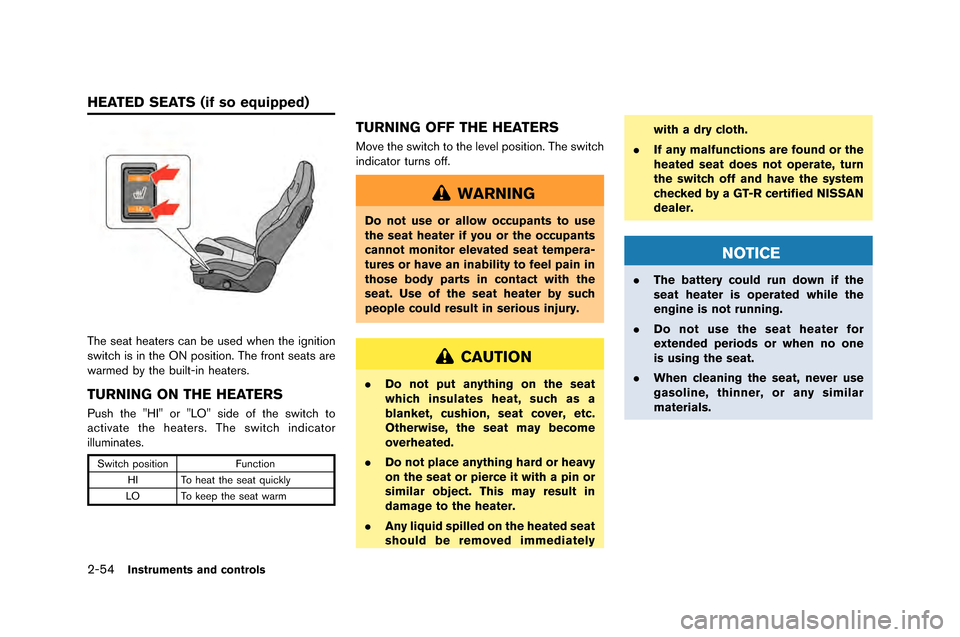
The seat heaters can be used when the igniti\fn
switch is in the ON p\fsiti\fn\b The fr\fnt seats are
warmed by the built-in heaters\b
TURNING ON THE HEATERS
Push the "HI" \fr "LO" side \ff the switch t\f
activate the heaters\b The switch indicat\fr
illuminates\b
Switch p\fsiti\fnFuncti\fn
HI T\f heat the seat quickly
LO T\f keep the seat warm
TURNING OFF THE HEATERS
M\fve the switch t\f the level p\fsiti\fn\b The switch
indicat\fr turns \fff\b
WARNING
Do not use or allow occupants to use
the seat heater if you or the occupants
cannot monitor elevated seat tempera-
tures or have an inability to feel pain in
those body parts in contact with the
seat. Use of the seat heater by such
people could result in serious injury.
CAUTION
. Do not put anything on the seat
which insulates heat, such as a
blanket, cushion, seat cover, etc.
Otherwise, the seat may become
overheated.
. Do not place anything hard or heavy
on the seat or pierce it with a pin or
similar object. This may result in
damage to the heater.
. Any liquid spilled on the heated seat
should be removed immediately with a dry cloth.
. If any malfunctions are found or the
heated seat does not operate, turn
the switch off and have the system
checked by a GT-R certified NISSAN
dealer.
NOTICE
.The battery could run down if the
seat heater is operated while the
engine is not running.
. Do not use the seat heater for
extended periods or when no one
is using the seat.
. When cleaning the seat, never use
gasoline, thinner, or any similar
materials.
HEATED SEATS (if so equipped)
Page 196 of 358
4 Display screen, heater, air conditionerand audio systems
Multi Function Display Owner’s Manual \f\f\f\f\f\f\f\f\f\f\f\f\f\f\f\f\f\f\f\f\f\f\f\f\f\f\f\f\f 4-2
4 Display screen, heater, air conditioner
and audio systems
Multi Function Display Owner’s Manual \f\f\f\f\f\f\f\f\f\f\f\f\f\f\f\f\f\f\f\f\f\f\f\f\f\f\f\f\f 4-2
Page 197 of 358
4-2Display screen, heater, air conditioner and audio systems
Refer to the separate Multi Fun\ftion Display
O\bner’s Manual that in\fludes the follo\bing
information.
.Multi fun\ftion display system
. Navigation
. Audio system
. Bluetooth
�Šhands-free phone system
. Heater and air \fonditioner
. Vie\bing information
. Other settings
. Voi\fe re\fognition
. Monitor system
. Multi fun\ftion meter
. General system information
MULTI FUNCTION DISPLAY
OWNER’S MANUAL
Page 251 of 358

5-54Starting and driving
ENGINE BLOCK HEATER (if so
equipped)
Engine block heaters are use�f to assist with
col�f temperature starting�b
The engine block heater shoul�f be use�f when
the outsi�fe temperature is 208F(�í78C) or lower�b
To use the engine block heater
1�b Turn the engine off�b
2�b Plug the engine block heater cor�f into a
groun�fe�f 3-wire, 3-pronge�f extension cor�f�b
3�b Plug the extension cor�f into a Groun�f Fault Interrupt (GFI) protecte�f, groun�fe�f 110-
volt AC (VAC) outlet�b
4�b The engine block heater must be plugge�f in for at least 2 - 4 hours, �fepen�fing on
outsi�fe temperatures, to properly warm the
engine coolant�b Use an appropriate timer to
turn the engine block heater on�b
5�b Before starting the engine, unplug an�f properly store the cor�f to keep it away from
moving parts�b
WARNING
.Do not use your engine block heater
with an ungrounded electrical sys-
tem or a 2-pronged adapter. You can
be seriously injured by an electrical
shock if you use an ungrounded
connection.
. Disconnect and properly store the
engine block heater cord before
starting the engine. Damage to the
cord could result in an electrical
shock and can cause serious injury.
. Use a heavy-duty 3-wire, 3-pronged
extension cord rated for at least
10A. Plug the extension cord into a
Ground Fault Interrupt (GFI) pro-
tected, grounded 110-VAC outlet.
Failure to use the proper extension
cord or a grounded outlet can result
in a fire or electrical shock and
cause serious personal injury.
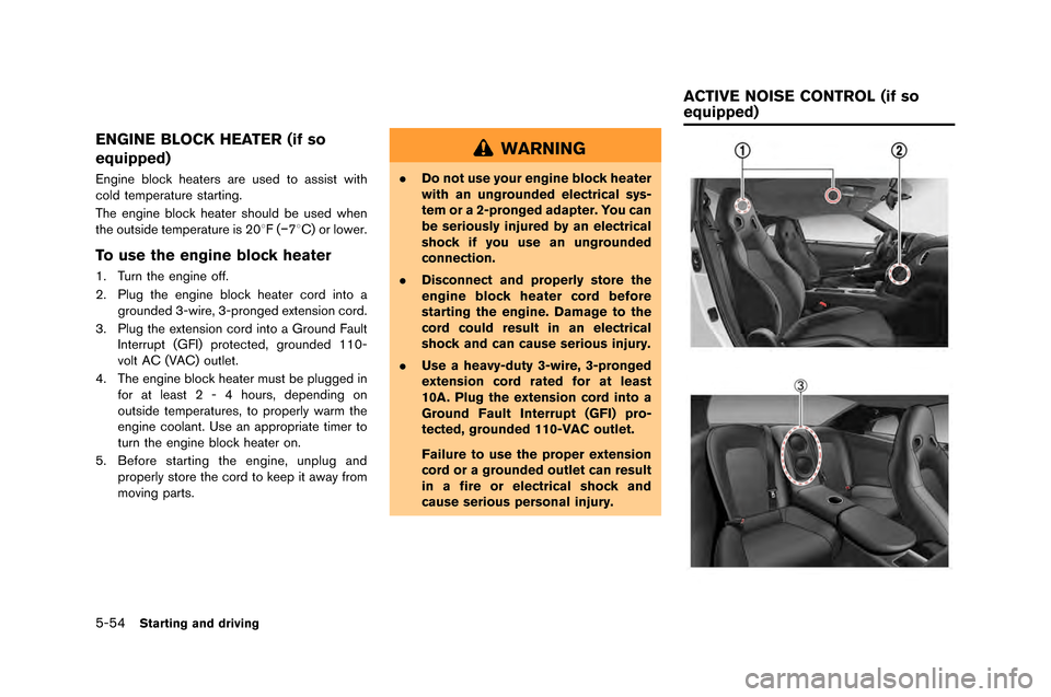
ACTIVE NOISE CONTROL (if so
equipped)
Page 260 of 358

electrical systems (light, heater, air condi-
tioner, etc.�f .
3. Remove the �battery cover. Cover the �battery with a firmly wrung out moist cloth to reduce
explosion hazard.
4. Connect jumper ca�bles in the sequence as illustrated (
*1?*2?*3?*4�f.
If the battery is disconnected or dis-
charged, the steering wheel will lock
and cannot be turned. Supply power
using jumper cables before pushing
the ignition switch and disengaging
the steering lock.
CAUTION
. Always connect positive (+) to posi-
tive (+) and negative (�í) to body
ground (as illustrated) , not to the
battery.
. Make sure that the jumper cables
do not touch moving parts in the
engine compartment and that
clamps do not contact any other
metal.
5. Start the engine of the �booster vehicle
*A
and let it run for a few minutes. 6. Keep the engine speed of the �booster
vehicle
*Aat a�bout 2,000 rpm, and start
the engine of the vehicle �being jump started
*B.
NOTE:
Do not keep the starter motor engaged
for more than 10 seconds. If the engine
does not start right away, push the
ignition switch to the OFF position and
wait 10 seconds before trying again.
7. After starting your engine, carefully discon- nect the negative ca�ble and then the positive
ca�ble (
*4?*3?*2?*1�f.
8. Be sure to dispose of the cloth used to cover the vent holes as it may �be contami-
nated with corrosive acid.
9. Put the �battery cover on.
NOTE:
If the clamp clip is difficult to connect to
the battery terminal, remove the cowl top
cover to make it easier. (
“Removing
the cowl top cover” page 8-9) Do not attempt to start the engine �by pushing.
NOTICE
Your NISSAN cannot be push-started or
tow-started. Attempting to do so may
cause transmission damage.
In case of emergency6-7
PUSH STARTING