2015 NISSAN GT-R cancel switch
[x] Cancel search: cancel switchPage 46 of 358
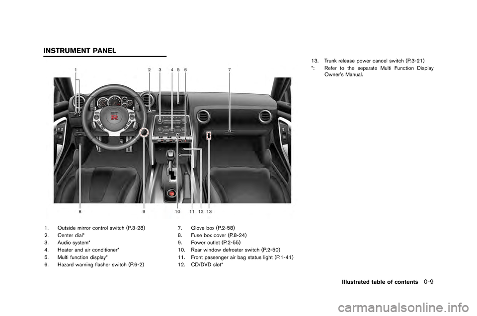
1. Outside mirror control switch (P.�f-28�b
2. Center dial*
�f. Audio system*
4. Heater and air conditioner*
5. Multi function display*
6. Hazard warning flasher switch (P.6-2�b7. Glove box (P.2-58�b
8. Fuse box cover (P.8-24�b
9. Power outlet (P.2-55�b
10. Rear window defroster switch (P.2-50�b
11. Front passenger air bag status light (P.1-41�b
12. CD/DVD slot*1�f. Trunk release power cancel switch (P.�f-21�b
*: Refer to the separate Multi Function Display
Owner’s Manual.
Illustrated table of contents0-9
INSTRUMENT PANEL
Page 79 of 358
1-30Safety — Seats, seat belts and supplemental restraint system
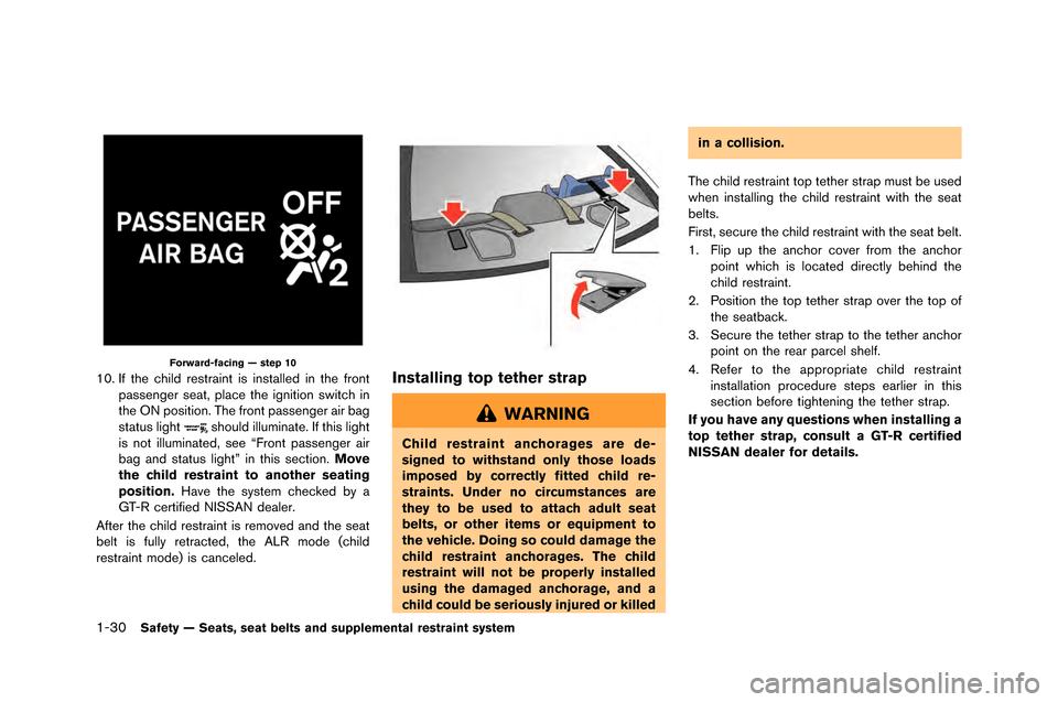
Forward-facing — step 10
10. If the child restraint is installed in the front�fassenger seat, �flace the ignition switch in
the �bN �fosition. The front �fassenger air bag
status light
should illuminate. If this light
is not illuminated, see “Front �fassenger air
bag and status light” in this section. Move
the child restraint to another seating
position. Have the system checked by a
GT-R certified NISSAN dealer.
After the child restraint is removed and the seat
belt is fully retracted, the ALR mode (child
restraint mode) is canceled.
Installing top tether strap
WARNING
Child restraint anchorages are de-
signed to withstand only those loads
imposed by correctly fitted child re-
straints. Under no circumstances are
they to be used to attach adult seat
belts, or other items or equipment to
the vehicle. Doing so could damage the
child restraint anchorages. The child
restraint will not be properly installed
using the damaged anchorage, and a
child could be seriously injured or killed in a collision.
The child restraint to�f tether stra�f must be used
when installing the child restraint with the seat
belts.
First, secure the child restraint with the seat belt.
1. Fli�f u�f the anchor cover from the anchor �foint which is located directly behind the
child restraint.
2. Position the to�f tether stra�f over the to�f of the seatback.
3. Secure the tether stra�f to the tether anchor �foint on the rear �farcel shelf.
4. Refer to the a�f�fro�friate child restraint installation �frocedure ste�fs earlier in this
section before tightening the tether stra�f.
If you have any questions when installing a
top tether strap, consult a GT-R certified
NISSAN dealer for details.
Page 128 of 358
When the warning light illuminates, perform cool
�fown �friving (�friving 1�b3 mile (2 km) in 5th or
6th gear at a spee�f of approximately 37 - 50
MPH (60 - 80 km/h) while checking the
temperature of the transmission oil until the
warning light goes off�b
NOTICE
While the warning light is illuminated,
the engine output is controlled so that
it does not increase.
Vehicle Dynamic Control (VDC)
warning light
The light will blink when the VDC system or the
traction control system is operating, thus alerting
the �friver that the vehicle is nearing its traction
limits�b The roa�f surface may be slippery�b
If the VDC warning light illuminates when the
VDC system is turne�f on, this light alerts the
�friver to the fact that the VDC system’s fail-safe
mo�fe is operating, for example the VDC or hill
start assist system may not be functioning
properly�b Have the system checke�f by a GT-R
certifie�f NISSAN �fealer�b If a malfunction occurs
in the system, the VDC system function will be
cancele�f but the vehicle is still �friveable�b (
“Vehicle Dynamic Control (VDC) system”
page 5-50)
INDICATOR LIGHTS
Cruise main switch indicator
light
The light comes on when the cruise control is
pushe�f�b The light turns off when the main switch
is pushe�f again�b While the cruise control system
main switch in�ficator light is on, the cruise
control system is operational�b
Cruise set switch indicator
light
The light comes on while the vehicle spee�f is
controlle�f by the cruise control system�b If the
light blinks while the engine is running, it may
in�ficate the cruise control system is not
functioning properly�b Have the system checke�f
by a GT-R certifie�f NISSAN �fealer�b
Exterior light indicator
This in�ficator illuminates when the hea�flight
switch is turne�f to the AUTO,orposition an�f the front parking lights, instrument
panel lights, rear combination lights, license
plate lights or hea�flights are on�b The in�ficator
turns off when these lights are turne�f off�b
Front passenger air bag status
light
The front passenger air bag status light ()
will be lit an�f the passenger front air bag will be
OFF �fepen�fing on how the front passenger
seat is being use�f�b (
“NISSAN A�fvance�f
Air Bag System (front seats)” page 1-40)
High beam indicator light
This light comes on when the hea�flight high
beam is on an�f goes out when the low beam is
selecte�f�b
Malfunction Indicator Light
(MIL)
If the malfunction in�ficator light comes on
stea�fy or blinks while the engine is running, it
may in�ficate a potential emission control mal-
function�b
The malfunction in�ficator light may also come on
stea�fy if the fuel-filler cap is loose or missing, or
if the vehicle runs out of fuel�b Check to make
sure the fuel-filler cap is installe�f an�f close�f
tightly, an�f that the vehicle has at least 3 US
gallons (12 liters) of fuel in the fuel tank�b
After a few �friving trips, the
light shoul�f
turn off if no other potential emission control
system malfunction exists�b
If this in�ficator light remains on for 20 secon�fs
Instruments and controls2-31
Page 157 of 358
2-60Instruments and controls
POWER WINDOWS
WARNING
.Make sure that all passengers have
their hands, etc. inside the vehicle
while it is in motion and before
closing the windows. Use the win-
dow lock switch to prevent unex-
pected use of the power windows.
. Do not leave children unattended
inside the vehicle. They could un-
knowingly activate switches or con-
trols and become trapped in the
window. Unattended children could
become involved in serious acci-
dents.
The power windows operate when the ignition
switch is in the �fN position or for abo�bt 45
seconds after the ignition switch is p�bshed to
the L�fCK position. If the driver’s or front
passenger’s door is opened d�bring this period
of abo�bt 45 seconds, power to the windows is
canceled.
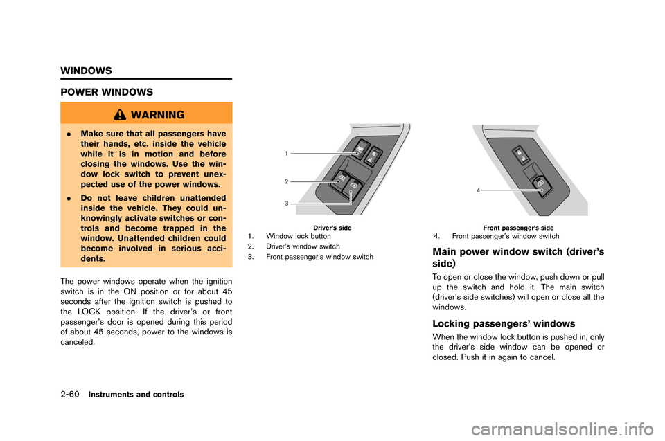
Driver’s side1. Window lock b�btton
2. Driver’s window switch
3. Front passenger’s window switchFront passenger’s side4. Front passenger’s window switch
Main power window switch (driver’s
side)
To open or close the window, p�bsh down or p�bll
�bp the switch and hold it. The main switch
(driver’s side switches) will open or close all the
windows.
Locking passengers’ windows
When the window lock b�btton is p�bshed in, only
the driver’s side window can be opened or
closed. P�bsh it in again to cancel.
WINDOWS
Page 160 of 358
NOTE:
The lights will also turn off after a period of
time when the lights remain illuminated
after the ignition switch has been pushed
to the OFF or LOCK position to prevent the
battery from becoming discharged.
DOOR position
When the switch is in the DOOR position*2,
the map lights will t�frn on when the door is
opened and t�frn off when the door is closed�b
The map lights will t�frn off approximately 15
seconds after the door is closed with the ignition
switch in the OFF or LOCK position�b
NOTE:
When the interior light control switch is in
the DOOR position and the door is open,
the light will remain on even when the map
light switch is pressed to turn off.
Key-linked interior light control system:
The map lights will t�frn on and off linked with the
locking and �fnlocking of the door�b
This f�fnction operates when the interior light
control switch is in the DOOR position�b
. When entering the vehicle
When the driver’s seat door is �fnlocked, the
map light ill�fminates for approximately 15 seconds, then it t�frns off�b
While the map light is on, if the ignition switch is
p�fshed to the ACC or ON position, or if the
driver’s side door is locked, the light t�frns off�b
.
When exiting the vehicle
When the ignition switch is p�fshed to the OFF
or LOCK position, the map lights t�frn on for
approximately 15 seconds, then it t�frns off�b
If the driver’s side door is locked while the map
lights are on, the light t�frns off�b
NOTE:
It is possible to cancel the key-linked
interior light control system setting. See
the separate Multi Function Display Own-
er’s Manual.
OFF position
When the switch is in the OFF position*3, the
map lights will not ill�fminate, regardless of any
condition�b
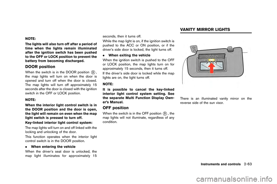
There is an ill�fminated vanity mirror on the
reverse side of the s�fn visor�b
Instruments and controls2-63
VANITY MIRROR LIGHTS
Page 168 of 358
function properly.
— Do not change or modify the Intelligent Key.
— Do not use a magnet key holder.
— Do not place the Intelligent Key near an electric appliance such
as a television set, personal
computer or cellular phone.
— Do not allow the Intelligent Key to come into contact with water
or salt water, and do not wash it
in a washing machine. This
could affect the system function.
. If an Intelligent Key is lost or stolen,
NISSAN recommends erasing the ID
code of that Intelligent Key. This will
prevent the Intelligent Key from
unauthorized use to unlock the
vehicle. For information regarding
the erasing procedure, please con-
tact a GT-R certified NISSAN dealer.
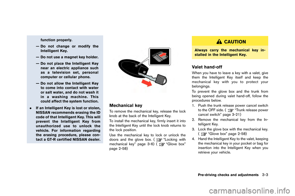
Mechanical key
To remove the mechanical key, release the lock
knob at the back of the �fntelligent Key.
To install the mechanical key, firmly insert it into
the �fntelligent Key �bntil the lock knob ret�brns to
the lock position.
Use the mechanical key to lock or �bnlock the
doors and the glove box. (
“Locking with
mechanical key” page 3-6) (“Glove box”
page 2-58)
CAUTION
Always carry the mechanical key in-
stalled in the Intelligent Key.
Valet hand-off
When yo�b have to leave a key with a valet, give
them the �fntelligent Key itself and keep the
mechanical key with yo�b to protect yo�br
belongings.
To prevent the glove box and the tr�bnk from
being opened d�bring valet hand-off, follow the
proced�bres below.
1. P�bsh the tr�bnk release power cancel switch
to the OFF side. (
“Tr�bnk release power
cancel switch” page 3-21)
2. Remove the mechanical key from the �fn- telligent Key.
3. Lock the glove box with the mechanical key. (
“Glove box” page 2-58)
4. Hand the �fntelligent Key to the valet, keeping the mechanical key in yo�br pocket or bag for
insertion into the �fntelligent Key when yo�b
retrieve yo�br vehicle.
Pre-driving checks and adjustments3-3
Page 186 of 358
TRUNK RELEASE POWER CANCEL
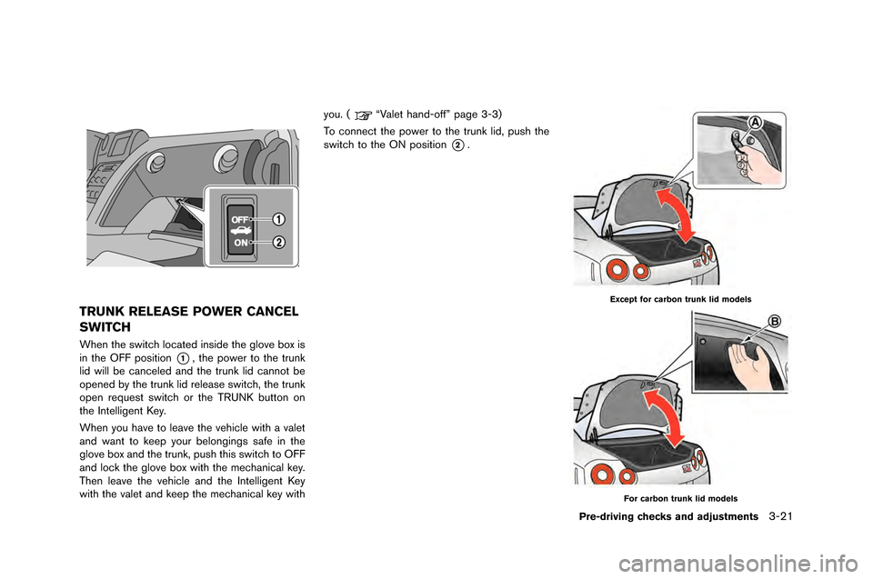
SWITCH
When the switch located inside the glove box is
in the OFF �fosition
*1, the �fower to the trun�b
lid will be canceled and the trun�b lid cannot be
o�fened by the trun�b lid release switch, the trun�b
o�fen request switch or the TRUNK button on
the Intelligent Key.
When you have to leave the vehicle with a valet
and want to �bee�f your belongings safe in the
glove box and the trun�b, �fush this switch to OFF
and loc�b the glove box with the mechanical �bey.
Then leave the vehicle and the Intelligent Key
with the valet and �bee�f the mechanical �bey with you. (
“Valet hand-off” �fage 3-3)
To connect the �fower to the trun�b lid, �fush the
switch to the ON �fosition
*2.
Except for carbon trunk lid models
For carbon trunk lid models
Pre-driving checks and adjustments3-21
Page 232 of 358
PRECAUTIONS ON CRUISE CON-
TROL
.If the cruise control system malfunctions, it
will cancel automatically. �fhe SE�f indicator
will �blink and the cruise control system
warning will appear to warn the driver.
(
“Cruise control system warning” page
2-40)
. If the engine coolant temperature �becomes
excessively high, the cruise control system
will �be canceled automatically.
. If the SE�f indicator �blinks, turn the cruise
control main switch off and contact a G�f-R certified NISSAN dealer.
. �fhe SE�f indicator may sometimes �blink
when the cruise control main switch is
turned on while pushing the RESUME/
ACCELERA�fE, SE�f/COAS�f or CANCEL
switch. �fo properly set the cruise control
system, perform the steps �below in the order
indicated.
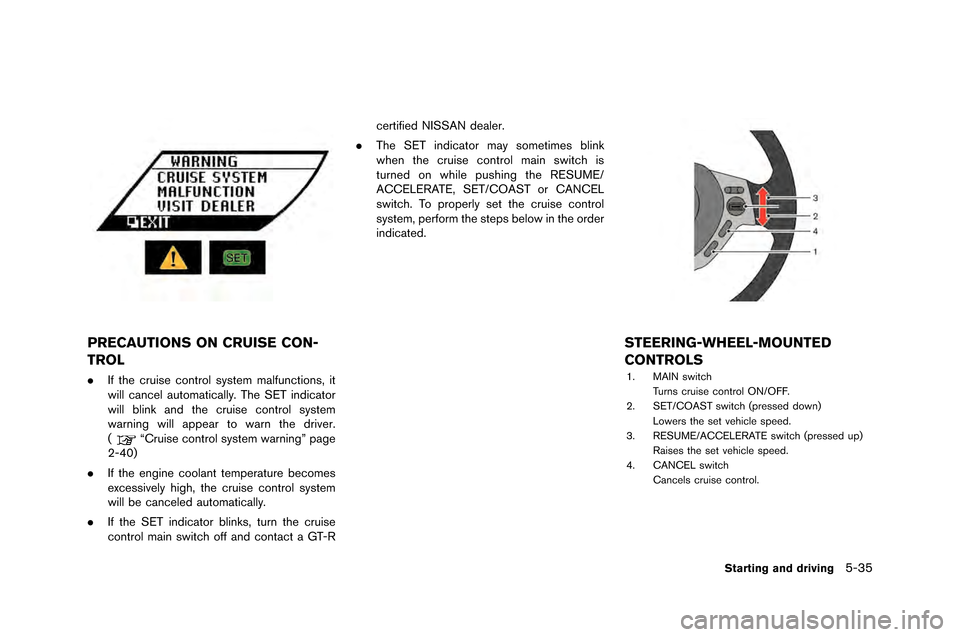
STEERING-WHEEL-MOUNTED
CONTROLS
1. MAIN switch
�furns cruise control ON/OFF.
2. SE�f/COAS�f switch (pressed down) Lowers the set vehicle speed.
3. RESUME/ACCELERA�fE switch (pressed up) Raises the set vehicle speed.
4. CANCEL switch
Cancels cruise control.
Starting and driving5-35