2015 MITSUBISHI OUTLANDER SPORT steering wheel adjustment
[x] Cancel search: steering wheel adjustmentPage 24 of 384
Front seats
Seat and restraint systems 4-3
4
Safety equipment cannot prevent injury or death in all motor vehicle accidents. You can help reduce the risk of injury or death, how- ever, by following the
instructions in this
manual.
N00401800399
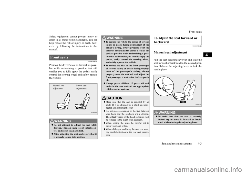
Position the driver’s seat
as far back as possi-
ble while maintaining a position that stillenables you to fully apply the pedals, easily control the steering wheel and safely operate the vehicle.
N00401900228
Pull the seat adjusting lever up and slide theseat forward or backward to the desired posi- tion. Release the adjusting lever to lock the seat in place.
Front seats
WA R N I N G Do not attempt to adjust the seat while driving. This can cause loss of vehicle con- trol and result in an accident. After adjusting the seat, make sure that it is securely locked into position.Manual seat adjustment
Power seat adjustment
To reduce the risk to the driver of serious injury or death during deployment of the driver’s airbag, always properly wear the seat belt and adjust th
e driver’s seat as far
back as possible while maintaining a posi-tion that still enables
you to fully apply the
pedals, easily control the steering wheel, and safely operate the vehicle. To reduce the risk to the front passenger of serious injury or death during deploy-ment of the passenger’s airbag, always properly wear the seat belt and adjust the front passenger’s seat as far back as possi-ble. Always place children 12 years old and under in the rear seat and use appropriate child restraint systems.CAUTION Make sure that the seat is adjusted by an adult. If it is adjusted by a child, an unex-pected accident might occur. Do not place a cushion or the like between your back and the seatback while driving. The effectiveness of the head restraints will be reduced in the event of an accident. When sliding the seats, be careful not to catch your hand or leg. When sliding or reclining the seat rearward, pay careful attention to the rear seat passen- gers.WA R N I N G
To adjust the seat forward or backward Manual seat adjustment
WA R N I N G To make sure that the seat is securely locked, try to move it forward or back- ward without using the adjusting lever.
BK0206700US.bo
ok 3 ページ 2014年3月25日 火曜日 午後4時42分
Page 64 of 384
5
Features and controlsBreak-in recommendation
s ..............................................................5-3
Keys ..........................................
.......................................................5-3
Electronic immobilizer (Anti-thef
t starting system) ........................5-4
Keyless entry system (if so equipped) .............................................5-7Free-hand Advanced Security Transmitter (F.A.S.T.-key) (if so equipped)
.................................................
........................ 5-11
Door locks .......................
...............................................................5-28
Power door locks ............
...............................................................5-30
Child safety locks for r
ear door .....................................................5-31
Liftgate ......................................
.....................................................5-32
Inside liftgate releas
e .............................................
........................5-33
Theft-alarm system
................................................
........................5-33
Power window control
...........................................
........................5-36
Sunshade (if so equi
pped)..............................................................5-39
Parking brake ..................
...............................................................5-40
Steering wheel height and reach adjustment ..................................5-41Inside rearview mirro
r ...........................................
........................5-41
Outside rearview mirr
ors ...............................................................5-43
Ignition switch ......
.................................................
........................5-44
Starting the engine
.................................................
........................5-45
Manual transaxle (if so equipped) .................................................5-47 Continuously variable transmission
(CVT) (if so equipped).........5-49
Electronically controlled 4WD system (if so equipped)................5-564-wheel drive operation
.........................................
........................5-58
Inspection and maintenance following rough road operation ........5-61 Cautions on the handling of 4-wheel drive vehicles ......................5-61Service brake ..................
...............................................................5-62
Hill start assist .......
.................................................
........................5-63
Brake assist system
...............................................
......................... 5-64
Anti-lock braking syst
em .....................................
......................... 5-65
Electric power steering syst
em (EPS) ........................................... 5-67
Active stability control
(ASC) ....................
................................... 5-68
Cruise control (if so eq
uipped) ...................................................... 5-71
Tire pressure monitoring
system ................................................... 5-75
Rear-view camera (if so eq
uipped) ................................................ 5-79
Instrument cluster
.................................................
......................... 5-81
Multi-information disp
lay ....................................
......................... 5-83
Indicator light, warning light, and information screen disp
lay list ................................................. 5-105
Indicators .................................
.................................................... 5-117
Warning lights ................
.............................................................. 5-118
Information screen disp
lay .......................................................... 5-119
Combination headlights and dimmer switch ............................... 5-121 Headlight leveling switch (if so equipped).................................. 5-127Turn signal lever ..
.................................................
....................... 5-127
Hazard warning flasher
switch .................................................... 5-128
Front fog light switch (if
so equipped) ........................................ 5-128
Wiper and washer swit
ch ......................................
....................... 5-129
Electric rear window def
ogger switch ......................................... 5-134
Horn switch .............................
.................................................... 5-134
Link System (if so equi
pped) .....................
................................. 5-135
Bluetooth
® 2.0 interface (if so e
quipped) .................................... 5-135
USB input terminal (if so
equipped) ........................................... 5-157
Sun visors ......................
.................................................
............. 5-159
12 V power outlets .........
.................................................
............. 5-160
Interior lights .................
.................................................
............. 5-161
BK0206700US.bo
ok 1 ページ 2014年3月25日 火曜日 午後4時42分
Page 104 of 384
Steering wheel height and reach adjustment
Features and controls 5-41
5
N00511500228
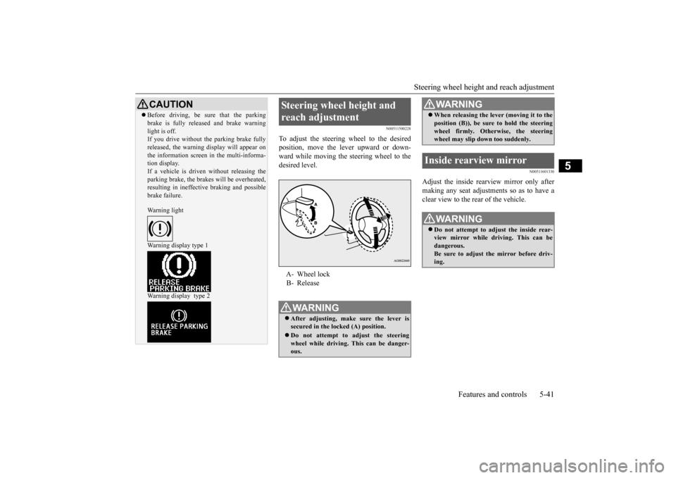
To adjust the steering wheel to the desired position, move the lever upward or down-ward while moving the steering wheel to the desired level.
N00511601330
Adjust the inside rearview mirror only after making any seat adjustments so as to have a clear view to the rear of the vehicle.
CAUTION Before driving, be sure that the parking brake is fully released and brake warning light is off. If you drive without the parking brake fully released, the warning display will appear onthe information screen in the multi-informa- tion display. If a vehicle is driven without releasing theparking brake, the brakes will be overheated, resulting in ineffective braking and possible brake failure. Warning light Warning display type 1 Warning display type 2
Steering wheel height and reach adjustment A- Wheel lock B- ReleaseWA R N I N G After adjusting, make sure the lever is secured in the locked (A) position. Do not attempt to adjust the steering wheel while driving. This can be danger-ous.
When releasing the lever (moving it to the position (B)), be sure to hold the steering wheel firmly. Otherwise, the steering wheel may slip down too suddenly.
Inside rearview mirror
WA R N I N G Do not attempt to adjust the inside rear- view mirror while driving. This can bedangerous. Be sure to adjust the mirror before driv- ing.WA R N I N G
BK0206700US.bo
ok 41 ページ 2014年3月25日 火曜日 午後4時42分
Page 141 of 384
Tire pressure monitoring system 5-78 Features and controls
5
TPMS malfunctions may occur for a variety of reasons, including the installation of replacement or alternate tires or wheels on the vehicle that prevent the TPMS from function-ing properly. Always check the TPMS mal- function telltale after replacing one or more tires or wheels on your vehicle to ensure thatthe replacement or alternate tires and wheels allow the TPMS to continue to function prop- erly.
N00532801524
1. If the tire pressure monitoring systemwarning light illuminates, avoiding hardbraking, sharp steering maneuvers and high speeds. You should stop and adjust the tires to the proper inflation pressure assoon as possible. Adjust the spare tire at the same time. Refer to “Tires” on page 9-13.
2. If the tire pressure monitoring system warning light remains illuminated after you have been driving for about 20 min- utes after you adjust the tire inflation pres-sure, one or more of the tires may have a puncture. Inspect the tire and if it has a puncture, have it repaired by an autho-rized Mitsubishi Motors dealer as soon as possible.
The tire pressure monitoring system may not work normally in the following circum- stances: A wireless facility or device using the same frequency is near the vehicle. Snow or ice is stuck inside the fenders and/or on the wheels. The tire inflation pressure sensor’s battery is dead.
If the warning light/display illu- minates while driving
NOTE
In addition, the warning display is displayed on the information screen in the multi-infor- mation display. When inspecting or adjusting the tire pres- sure, do not apply excessive force to the valve stem to avoid breakage.
After inspecting or adjusting the tire pres- sure, always reinstall the valve cap on the valve stem. Without the valve cap, dirt or moisture could get into the valve, resulting in damage to thetire inflation pressure sensor. Do not use metal valve caps, which may cause a metal reaction, resulting in corrosion and damage of the tire inflation pressure sen- sors. Once adjustments have been made, the warn- ing light will go off after a few minutes ofdriving.WA R N I N G If the warning light/display illuminates while you are driving, avoid hard braking, sharp steering maneuvers and high speeds.Driving with an under-inflated tire adversely affects vehicle performance and can result in an accident.NOTE
CAUTION If a tire has a puncture, replace that tire with the spare tire. Driving on a punctured tire could lead to an accident. The warning light/display may not illuminate immediately in the event of a tire blowout or rapid leak.NOTE
To avoid the risk of damage to the tire infla- tion pressure sensors, have any punctured tire repaired by an authorized Mitsubishi Motors dealer. If the tire repair is not done byan authorized Mitsubishi Motors dealer, it is not covered by your warranty. Do not use an aerosol puncture-repair spray on any tire. Such a spray could damage the tire inflationpressure sensors. Have any puncture repaired by an authorized Mitsubishi Motors dealer.
BK0206700US.bo
ok 78 ページ 2014年3月25日 火曜日 午後4時42分
Page 190 of 384
Headlight leveling switch (if so equipped)
Features and controls 5-127
5
N00537100105
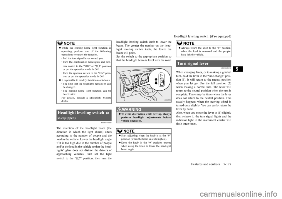
The direction of the headlight beam (the direction in which the light shines) altersaccording to the number of people and the load in the vehicle. Lower the headlight angle if it is too high due to the number of peopleand/or the load in the vehicle so that the head- lights’ glare does not distract the drivers of approaching vehicles. First set the light switch to the “ ” position, then turn the
headlight leveling switch knob to lower the beam. The greater the number on the head- light leveling switch knob, the lower the beam will point.Set the switch to the appropriate position so that the headlight beam is level with the road.
N00522601532
When changing lanes, or to making a gradual turn, hold the lever in
the “lane change” posi-
tion (1). It will return to the neutral positionwhen you let go. Use
the full position (2)
when making a normal turn. The lever will return to the neutral position when the turn iscomplete. There may be times when the lever does not return to the neutral position. This usually happens when the steering wheel isturned only slightly. You can easily return the lever by hand. Also, when you move the lever to (1) slightlythen release it, the turn signal lights and the indicator light in the instrument cluster will flash three times.
NOTE
While the coming home light function is operating, perform one of the following operations to cancel the function. • Pull the turn signal lever toward you.• Turn the combination headlights and dim- mer switch to the “ ” or “ ” position or put the operation mode in ON. • Turn the ignition switch to the “ON” posi- tion or put the operation mode in ON.
It is possible to modify functions as follows: • The time that the headlights remain on can be changed. • The coming home light function can be deactivated. For details, consult a Mitsubishi Motors dealer.
Headlight leveling switch
(if
so equipped)
WA R N I N G To avoid distraction while driving, always perform headlight adjustments beforevehicle operation.NOTE
Start adjusting when
the knob is at the “0”
position (when the beam is at its highest). Keep the knob in the “0” position except when using the knob to lower the headlightbeam angle.
Always return the knob to the “0” position when the load is removed and the people have left the vehicle.
Turn signal lever
NOTE
BK0206700US.book
127 ページ 2014年3月25日 火曜日 午後4時42分
Page 381 of 384
Alphabetical index 12-4
12
Operation under adverse driving conditions
...
8-13 Outside rearview mirrors
.....................
5-43
Overheating
......................
...................
8-4
P
Parking
.........................
.......................
6-6
Parking brake break-in
....................
9-21
Parking brake lever stroke
...............
9-21
Parking brake
....................
.................
5-40
Parking lights (type 1)
Bulb capacity
................
.................
9-29
Replacement
.................
.................
9-33
Parking lights (type 2)
Bulb capacity
................
.................
9-29
Replacement
.................
.................
9-35
Polishing
.......................
.....................
9-41
Power brakes
.....................
.................
5-62
Power outlet
..................
...................
5-160
Power steering
Fluid
........................
.....................
11-5
Power windows
.................
.................
5-36
Puncture (Tire changing)
.......................
8-5
R
Radio
General information about your radio 7-59
Reading lights
Bulb capacity
..................
................
9-30
Rear axle oil
..............................
9-11
, 11-5
Rear combination lights
Bulb capacity
..................
................
9-29
Replacement
...................
................
9-35
Rear side-marker lights
Bulb capacity
..................
................
9-29
Replacement
...................
................
9-35
Rear turn signal light
Bulb capacity
..................
................
9-29
Replacement
...................
................
9-35
Rear-view camera
...............
................
5-79
Rearview mirror
Inside rearview mirror
.....................
5-41
Outside rearview mirrors
.................
5-43
Replacement of light bulbs
...................
9-29
Replacing tires and wheels
...................
9-18
Reporting Safety Defects
.....................
10-2
S
Safe driving techniques
.........................
6-4
Seat belt
......................
.......................
4-11
Adjustable seat belt shoulder anchor
.4-16
Child restraint systems
.....................
4-18
Front passenger seat belt warning light
.....
4-16 Maintenance and inspection
.............
4-26
Seat belt extender
............................
4-17
Seat belt force limitter
.....................
4-18
Seat belt pre-tensioners
...................
4-17
Seat belt use during pregnancy
.........
4-17
Seats
..........................
..........................
4-2
Arm rest
.......................
...................
4-7
Front seats
....................
...................
4-3
Head restraints
.................
................
4-7
Heated seat
...................
...................
4-6
Seats and restraint systems
................
4-2
Service brake
.....................
.................
5-62
Service precautions
...............
................
9-2
Side turn signal light
Bulb capacity
................
.................
9-29
Snow tires
.....................
.....................
9-20
Spark plugs
...................
.....................
9-22
Starting the engine
..............................
5-45
Steering
Power steering fluid
........................
11-5
Steering wheel height and reach adjustment 5-41
Stop lights
Bulb capacity
................
.................
9-29
Replacement
.................
.................
9-35
Storage spaces
...................
...............
5-165
Sun visors
.....................
...................
5-159
Sunshade
......................
.....................
5-39
Supplemental Restraint System
............
4-26
How the Supplemental Restraint System works
.....................
.....................
4-29
BK0206700US.bo
ok 4 ページ 2014年3月25日 火曜日 午後4時42分