2015 MITSUBISHI OUTLANDER window
[x] Cancel search: windowPage 127 of 446
Sunroof (if so equipped) 5-50 Features and controls
5
N00551400014
Wind buffeting can be de
scribed as the per-
ception of pressure on the ears or a boomingor rumbling sound. Your
vehicle may exhibit
wind buffeting when driving with one or both rear door windows down or partially opened.This is a normal occurre
nce that can be mini-
mized. If the buffeting
occurs with the rear
door windows open, open the front door win- dows as well as the rear door windows to minimize the condition.
N00511001682
The sunroof can be opened and closed withthe ignition switch or the operation mode in ON.
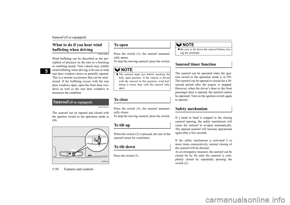
Press the switch (1), the sunroof automati- cally opens. To stop the moving sunroof, press the switch. Press the switch (3), the sunroof automati- cally closes. To stop the moving sunroof, press the switch. When the switch (2) is pressed, the rear of the sunroof raises
for ventilation.
Press the switch (3).
The sunroof can be operated when the igni- tion switch or the operation mode is in ON.The sunroof can be opened or closed for a 30- second period after th
e engine is stopped.
However, when the driver’s door or the frontpassenger door is opened, the sunroof cannot be operated. Turn on the ignition switch again to operate. If a hand or head is trapped in the closing sunroof opening, the safety mechanism willcause the sunroof to
re-open automatically.
The opened sunroof will become operational again after a few seconds. If the safety mechanism is activated 5 or more times consecutiv
ely, normal closing of
the sunroof will be aborted. As an emergency measure, the sunroof can be closed bit by bit until the sunroof is com-pletely closed by repeatedly pressing the switch (2).
What to do if you hear wind buffeting when driving Sunroof
(if so equipped)
To open
NOTE
The sunroof stops just before reaching the fully open position. If the vehicle is driven with the sunroof in this position, wind buf- feting is lower than with the sunroof fullyopen.
To close
To tilt up
To tilt down
NOTE
Be sure to tilt down the sunroof before clos- ing the sunshade.
Sunroof timer function
Safety mechanism
BK0211800US.book 50 ページ 2014年3月12日 水曜日 午後2時42分
Page 130 of 446

Steering wheel height
and reach adjustment
Features and controls 5-53
5
N00511501241
To adjust the steering wheel to the desired position, move the lever upward or down- ward while moving the steering wheel to the desired position.
N00511601327
Adjust the inside rearview mirror only after making any seat adjustme
nts so as to have a
clear view to the rear of the vehicle.
Adjust the inside mirror to maximize the view through the rear window. It is possible to move
the mirror up and down
to adjust its position.
CAUTION Before driving, be sure that the parking brake is fully released and brake warninglight is off.If you drive without the parking brake fully released, the warning di
splay will appear on
the information screen in the multi-informa-tion display. If a vehicle is driven without releasing the parking brake, the brakes will be overheated,resulting in ineffectiv
e braking and possible
brake failure. Warning light Warning display
Steering wheel height and reach adjustment
1- Wheel lock 2- ReleaseWA R N I N G After adjusting, make sure the lock lever is secured in the locked (1) position. Do not attempt to adjust the steering wheel while driving. This can be danger-ous.
Inside rearview mirror
1 2
WA R N I N G Do not attempt to adjust the inside rear- view mirror while driving. This can bedangerous.Be sure to adjust the mirrors before driv- ing.
To adjust the vertical mirror position
BK0211800US.book 53 ページ 2014年3月12日 水曜日 午後2時42分
Page 132 of 446

Ignition switch
Features and controls 5-55
5
“ACC” position or the ope
ration mode is put
in ON or ACC.Move the lever (A) to the same side as the mirror you wish to adjust. Press the switch (B) to adjust the mirror posi- tion.
N00549201100
The outside mirror can be folded in towards the side window to prevent damage when parking in tight locations.
N00549301228
When the rear window defogger switch is pressed with the engine running, the outside rearview mirrors are defogged or defrosted.Current will flow through the heater element inside the mirrors, thus clearing away frost or condensation.The indicator light (A) will illuminate while the defogger is on. The heater will be turned off automatically inabout 15 to 20 minutes depending on the out- side temperature.
N00512401696
[For vehicles equipped with the Free-hand Advanced Security Tr
ansmitter (F.A.S.T.-
key).] For information on operations for vehiclesequipped with the Free-hand Advanced Secu- rity Transmitter (F.A
.S.T.-key), refer to
“Free-hand Advanced
Security Transmitter
(F.A.S.T.-key): Engine switch” on page 5-16. [Except for vehicles equipped with the Free-hand Advanced Security Transmit-ter (F.A.S.T.-key).]
L- Left outside mirror adjustment R- Right outside mirror adjustment 1- Up 2- Down 3- Right 4- Left
NOTE
After adjusting, return the lever to the “•”(OFF) position (C).
To fold the mirror Door mirror heater
(if so equipped)
Ignition switch
BK0211800US.book 55 ページ 2014年3月12日 水曜日 午後2時42分
Page 136 of 446

Starting the engine
Features and controls 5-59
5
2. Insert the ignition key. 3. Press and hold the
brake pedal down with
your right foot. 4. Make sure the selector
lever is in the “P”
(PARK) position.5. Turn the ignition switch to the “ON” posi- tion and make certain that all warning lights are functioning properly beforestarting the engine. 6. Turn the ignition switch to the “START” position without pressi
ng the accelerator
pedal. Release the ignition switch when the engine starts.
After several attempts, you may experience that the engine still does not start. 1. Make sure that all electric devices, such as lights, air conditio
ning blower and rear
window defogger, are turned off.
2. While depressing the brake pedal, press the accelerator peda
l halfway and hold it
there, then crank th
e engine. Release the
accelerator pedal, immediately after the engine starts.3. If the engine still will not start, the engine could be flooded with too much gasoline. While depressing the brake pedal, pushthe accelerator pedal all the way down and hold it there, then crank the engine for 5 to 6 seconds. Retu
rn the ignition switch
to the “OFF” or “LOCK” position and release the accelerator pedal. Wait a fewseconds, and then crank the engine again for 5 to 6 seconds while depressing the brake pedal, but do no
t push the accelera-
tor pedal. Release the ignition key if the engine starts. If the
engine fails to start,
repeat these procedures
. If the engine still
will not start, cont
act your local Mitsubi-
shi Motors dealer or
a repair facility of
your choice for assistance.
When the ambient temperature is -22 °F (-30 °C) or lower, it may not be possible to startfrom a standstill even with the selector lever
in the “D” (DRIVE) or “R” (REVERSE) position.This occurs because the transaxle has not warmed up sufficiently
; it does not indicate a
problem. If this occu
rs, place the selector
lever in the “P” (PAR
K) position and let the
engine idle for at
least 10 minutes.
The transaxle will wa
rm up, and you will be
able to start normally. Do not leave the vehicle during warm-up operation. The MIVEC engine automatically switches its intake-valve control between a low-speed mode and a high-speed mode in accordance with driving conditions for maximum engineperformance.
NOTE
Minor noises may be heard on engine start- up. These will disappear as the engine warmsup.
When the engine is hard to start
Startability of automatic transaxle vehicle and CVT vehicle with ambient temperature of -22 °F (-30 °C) or lower
Using the MIVEC engine
NOTE
To protect the engine
, the high-speed mode
may not be selected wh
ile the engine coolant
temperature is low. In such a case, the engine revolutions do not rise to over 5,000 rpmeven if the accelerato
r pedal is depressed.
BK0211800US.book 59 ページ 2014年3月12日 水曜日 午後2時42分
Page 195 of 446
Rear-view camera (if so equipped) 5-118 Features and controls
5
A window tint that affects the radio wave signals is installed.
N00532900081
If new wheels with new tire inflation pressure sensors are installed, their ID codes must be programmed into the tire pressure monitoringsystem. Have tire and wheel replacement per- formed by an authorized Mitsubishi Motors dealer to avoid the ri
sk of damaging the tire
inflation pressure sensors. If the wheel replacement is not done by an authorized Mitsubishi Motors dealer
, it is not covered by
your warranty.
N00533001233
Your tire pressure monitoring system oper-ates on a radio frequency subject to Federal Communications Comm
ission (FCC) Rules
(For vehicles sold in U.S.A.) and IndustryCanada Rules (For vehicles sold in Canada). This device complies with part 15 of FCC Rules and Industry Ca
nada licence-exempt
RSS standard(s). Operation is subject to the following two con- ditions. This device may not
cause harmful inter-
ference. This device must ac
cept any interference
received, including interference that maycause undesired operation.
N00546201196
When the selector lever is in the “R”(REVERSE) position with the ignition switchin the “ON” position,
or the operation mode
is put in ON, the rear-view image will be dis- played on the screen of the Mitsubishi Multi-Communication System or the DISPLAY AUDIO. When the selector lever is shifted out of the “R” (REVERSE) position, the rear-view image will go off.
NOTE
Tire inflation pressures vary with the ambi- ent temperature. If the
vehicle is subjected to
large variations in am
bient temperature, the
tire inflation pressures may be under-inflated(causing the warning li
ght / display come on)
when the ambient temperature is relatively low. If the warning light / display comes on,adjust the tire inflation pressure.
Whenever the tires and wheels are replaced with new ones
CAUTION The use of non-genuine wheels will prevent the proper fit of the tire inflation pressuresensors, resulting air
leakage or damage of
the sensors.
General information
CAUTION Changes or modifica
tions not expressly
approved by the manufacturer for compli-ance could void the user’s authority to oper- ate the equipment.
Rear-view camera
(if so
equipped)
WA R N I N G Never rely solely on the rear-view camera to clear the area behind your vehicle. Always check visua
lly behind and all
around your vehicle fo
r persons, animals,
obstructions or other vehicles. Failure to do so can result in
vehicle damage, serious
injury or death. The rear-view camera is an aid system for backing up, but it is not a substitute for your visual confirmation. The view on the scre
en is limited, and
objects outside the view, such as under the bumper or around either corner of thebumper end, cannot be seen on the screen.
BK0211800US.book 118 ページ 2014年3月12日 水曜日 午後2時42分
Page 248 of 446
Combination headlights and dimmer switch
Features and controls 5-171
5
N00522501746
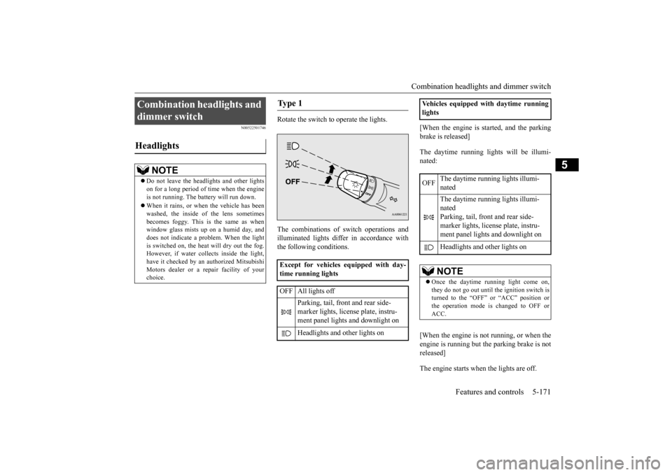
Rotate the switch to operate the lights. The combinations of
switch operations and
illuminated lights differ in accordance withthe following conditions.
[When the engine is started, and the parking brake is released] The daytime running light
s will be illumi-
nated: [When the engine is not running, or when the engine is running but the parking brake is notreleased] The engine starts when the lights are off.
Combination headlights and dimmer switch Headlights
NOTE
Do not leave the head
lights and ot
her lights
on for a long period of time when the engineis not running. The battery will run down. When it rains, or wh
en the vehicle has been
washed, the inside of the lens sometimes becomes foggy. This is the same as when window glass mists up
on a humid day, and
does not indicate a problem. When the light is switched on, the heat
will dry out the fog.
However, if water collects inside the light,have it checked by an
authorized Mitsubishi
Motors dealer or a repair facility of your choice.
Ty p e 1 Except for vehicles equipped with day- time running lights OFF All lights off
Parking, tail, front and rear side- marker lights, license plate, instru- ment panel lights and downlight on Headlights and other lights on
Vehicles equipped with daytime running lights OFF
The daytime running lights illumi- nated The daytime running lights illumi- nated Parking, tail, front and rear side- marker lights, licen
se plate, instru-
ment panel lights
and downlight on
Headlights and other lights onNOTE
Once the daytime running light come on, they do not go out until the ignition switch is turned to the “OFF” or “ACC” position or the operation mode is changed to OFF orACC.
BK0211800US.book 171 ページ 2014年3月12日 水曜日 午後2時42分
Page 255 of 446
Front fog light switch (if so equipped) 5-178 Features and controls
5
While the ECO mode is working, an ECO mode indicator will be turned on.
N00522801420
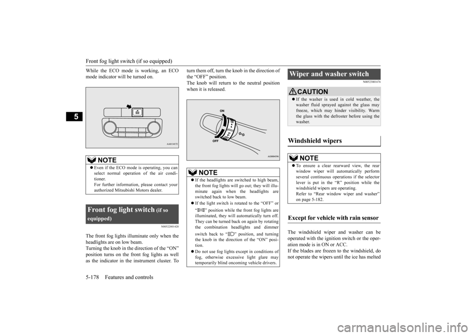
The front fog lights illuminate only when the headlights are on low beam. Turning the knob in the direction of the “ON”position turns on the front fog lights as well as the indicator in the instrument cluster. To
turn them off, turn the knob in the direction of the “OFF” position.The knob will return to the neutral position when it is released.
N00523001676
The windshield wiper and washer can be operated with the ignition switch or the oper-ation mode is in ON or ACC. If the blades are frozen to the windshield, do not operate the wipers
until the ice has melted
NOTE
Even if the ECO mode is operating, you can select normal operati
on of the air condi-
tioner.For further information, please contact your authorized Mitsubishi Motors dealer.
Front fog light switch
(if so
equipped)
NOTE
If the headlights are switched to high beam, the front fog lights will go out; they will illu-minate again when the headlights are switched back to low beam. If the light switch is rotated to the “OFF” or “ ” position while the
front fog lights are
illuminated, they will automatically turn off. They can be turned back on again by rotatingthe combination headlights and dimmer switch back to “ ” position, and turning the knob in the direction of the “ON” posi- tion. Do not use fog lights ex
cept in conditions of
fog, otherwise excessive light glare maytemporarily blind oncoming vehicle drivers.
Wiper and washer switch
CAUTION If the washer is used in cold weather, the washer fluid sprayed against the glass mayfreeze, which may hi
nder visibility. Warm
the glass with the defro
ster before using the
washer.
Windshield wipers
NOTE
To ensure a clear rearward view, the rear window wiper will au
tomatically perform
several continuous opera
tions if the selector
lever is put in the “R” position while thewindshield wipers are operating. Refer to “Rear window wiper and washer” on page 5-182.
Except for vehicle with rain sensor
BK0211800US.book 178 ページ 2014年3月12日 水曜日 午後2時42分
Page 256 of 446
Wiper and washer switch
Features and controls 5-179
5
and the blades are free
d, otherwise the wiper
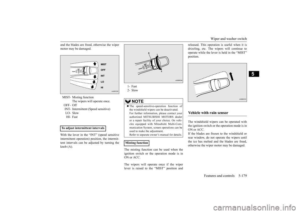
motor may be damaged. With the lever in the “INT” (speed sensitive intermittent operation)
position, the intermit-
tent intervals can be adjusted by turning theknob (A).
The misting function can be used when the ignition switch or the
operation mode is in
ON or ACC. The wipers will operate once if the wiper lever is raised to the “MIST” position and
released. This operation
is useful when it is
drizzling, etc. The wi
pers will continue to
operate while the lever is held in the “MIST” position. The windshield wipers can be operated with the ignition switch or
the operation mode is in
ON or ACC. If the blades are frozen to the windshield orrear window, do not operate the wipers until the ice has melted and the blades are freed, otherwise the wiper mo
tor may be damaged.
MIST- Misting function
The wipers will operate once.
OFF- OffINT- Intermittent (Speed sensitive) LO- Slow HI- Fast
To adjust intermittent intervals
1- Fast 2- Slow
NOTE
The speed-sensitive-operation function of the windshield wipers can be deactivated.For further informati
on, please contact your
authorized MITSUBISHI MOTORS dealer or a repair facility of your choice. On vehi-cles equipped with
Mitsubishi Multi-Com-
munication System, scre
en operations can be
used to make the adjustment.Refer to separate owne
r’s manual for details.
Misting function
Vehicle with rain sensor
BK0211800US.book 179 ページ 2014年3月12日 水曜日 午後2時42分