2015 MITSUBISHI OUTLANDER clock
[x] Cancel search: clockPage 370 of 446

Jack and tools
For emergencies 8-5
8
6. When you do not see any more steam or spray, open the hood. Look for obviousleaks, such as a split radiator hose. Be careful as components will be hot. Any leak source must be repaired.7. If there is no obvious leak source, check the coolant level in the engine coolant reserve tank. If there is
none, or if it is too
low, slowly add coolant. 8. If the engine coolant reserve tank needs coolant, you will probably also need toadd coolant to the radiator. Do not loosen or remove the radiator cap until the engine has cooled down.
9. Start the engine, a
nd slowly add coolant,
up to the bottom of the filler neck. Use plain water if you have to (and replace itwith the right coolant as soon as possible).
10. Replace the radiator cap and tighten it
fully. Check the engine coolant tempera-ture display on the mu
lti information dis-
play (Color liquid crystal display type) or the high coolant temperature warninglight (Mono-color liqui
d crystal display
type). You can start driving again when the high coolant temperature warningdoes not come on.
11. Have the system inspected by your autho-
rized Mitsubishi Motors
dealer or a repair
facility of your choice.
N00836601389
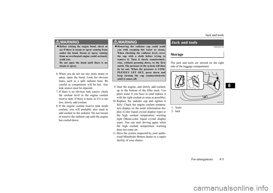
The jack and tools are stowed on the right side of the luggage compartment.
WA R N I N G Before raising the en
gine hood, check to
see if there is steam or spray coming fromunder the hood. Steam or spray comingfrom an overheated en
gine could seriously
scald you. Do not open the hood until there is nosteam or spray.
WA R N I N G Removing the radiat
or cap could scald
you with escaping hot water or steam.When checking the radiator level, coverthe cap with a cloth before trying to remove it. Turn it slowly counterclock- wise, without pressing down, to the firstnotch. The pressure in the system will then be let out. When the pressure is COM- PLETELY LET OUT, press down andkeep turning the cap counterclockwise until it comes off.
Jack and tools Storage 1- Tools 2- Jack
BK0211800US.book 5 ページ 2014年3月12日 水曜日 午後2時42分
Page 373 of 446

How to change a tire 8-8 For emergencies
8
N00849701296
1. Open the liftgate and use the bar to remove the cover (A)
over the tire hanger
mounting bolt. 2. With the wheel nut wrench, loosen the tire hanger mounting bolt by turning it coun- terclockwise.
3. Lift up the section of the tire hanger (B) that is marked with the arrow in the illus-tration and remove it from the hook (C). Then lower it and remove the tire.
N00849801457
1. On vehicles with
wheel covers, first
remove the covers (re
fer to “Wheel cov-
ers” on page 8-13). Then, loosen thewheel nuts with the wheel nut wrench. Do not remove the wheel nuts yet. 2. Place the jack under one of the jacking points (A) shown in the illustration. Use the jacking point closest to the tire you wish to change.
Do not use tire chains with your compact spare tire. Using a ch
ain could cause damage
to your vehicle and loss of the chains.
To remove the spare tire
CAUTION
CAUTION While checking the tir
e hanger, carefully
loosen the tire hanger mounting bolt. Loos-ening it too much could pull out the hook and cause the compact spare tire to drop.
CAUTION When hooking or unhooking the tire hanger, be sure to hold the tire hanger firmly to pre-vent it from dropping on your foot.
To change a tire
BK0211800US.book 8 ページ 2014年3月12日 水曜日 午後2時42分
Page 375 of 446

How to change a tire 8-10 For emergencies
8
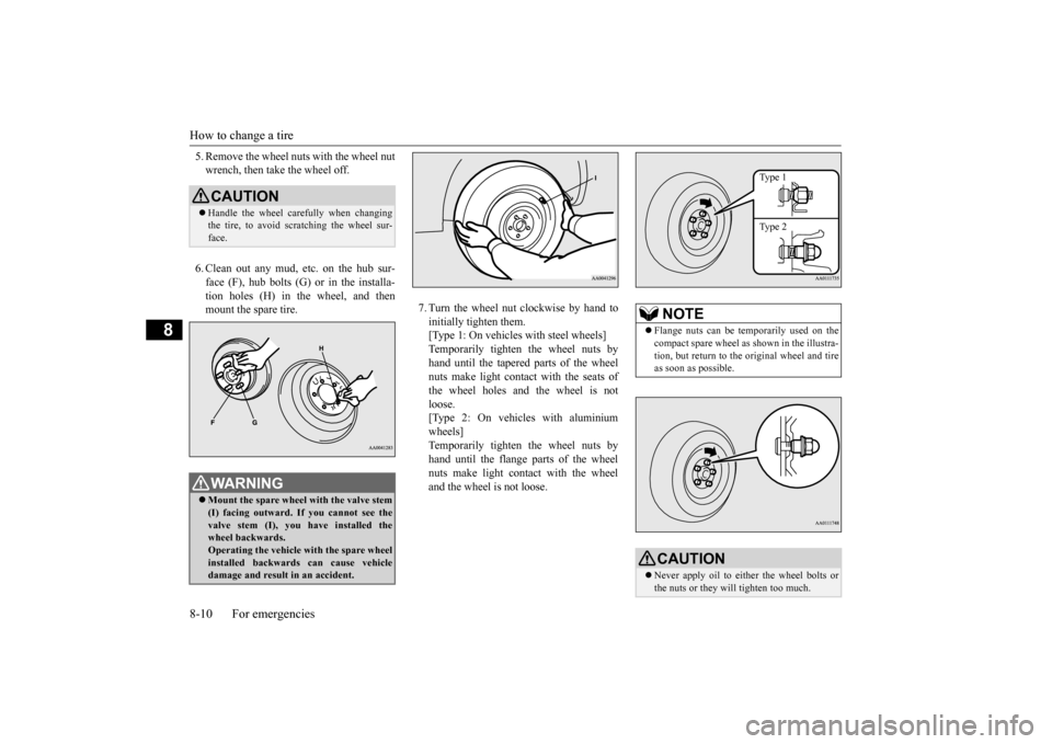
5. Remove the wheel nuts with the wheel nut wrench, then take the wheel off. 6. Clean out any mud, etc. on the hub sur- face (F), hub bolts (G)
or in the installa-
tion holes (H) in the wheel, and then mount the spare tire.
7. Turn the wheel nut clockwise by hand to initially tighten them. [Type 1: On vehicles
with steel wheels]
Temporarily tighten the wheel nuts by hand until the tapered parts of the wheel nuts make light contac
t with the seats of
the wheel holes and the wheel is not loose. [Type 2: On vehicles with aluminiumwheels] Temporarily tighten the wheel nuts by hand until the flange parts of the wheelnuts make light cont
act with the wheel
and the wheel is not loose.
CAUTION Handle the wheel carefully when changing the tire, to avoid scratching the wheel sur- face.WA R N I N G Mount the spare wheel with the valve stem (I) facing outward. If
you cannot see the
valve stem (I), you
have installed the
wheel backwards.Operating the vehicle with the spare wheel installed backwards can cause vehicle damage and result
in an ac
cident.
NOTE
Flange nuts can be te
mporarily used on the
compact spare wheel as shown in the illustra- tion, but return to the original wheel and tire as soon as possible.CAUTION Never apply oil to either the wheel bolts or the nuts or they will tighten too much.
Type 1 Type 2
BK0211800US.book 10 ページ 2014年3月12日 水曜日 午後2時42分
Page 376 of 446

How to change a tire
For emergencies 8-11
8
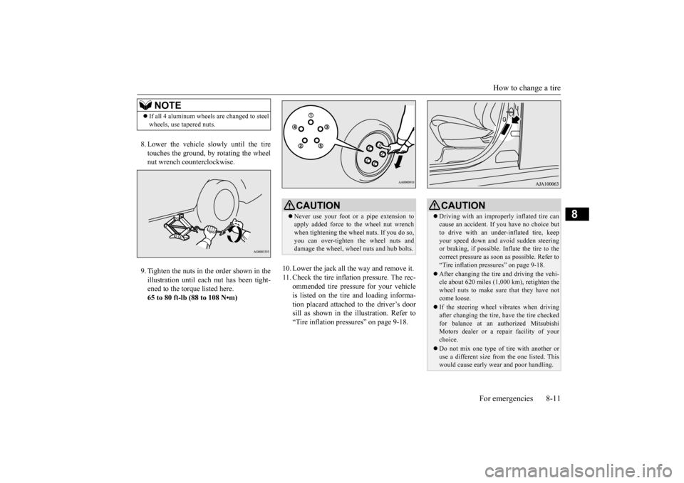
8. Lower the vehicle slowly until the tire touches the ground, by rotating the wheel nut wrench counterclockwise. 9. Tighten the nuts in the order shown in the illustration until each
nut has been tight-
ened to the torque listed here.65 to 80 ft-lb (88 to 108 N•m)
10. Lower the jack all the way and remove it. 11. Check the tire inflation pressure. The rec-
ommended tire pressure for your vehicleis listed on the tire
and loading informa-
tion placard attached to the driver’s door sill as shown in the illustration. Refer to“Tire inflation pressures” on page 9-18.
NOTE
If all 4 aluminum wheels are changed to steel wheels, use tapered nuts.
CAUTION Never use your foot or a pipe extension to apply added force to the wheel nut wrenchwhen tightening the wheel nuts. If you do so, you can over-tighten the wheel nuts and damage the wheel, wheel nuts and hub bolts.
CAUTION Driving with an imprope
rly inflated tire can
cause an accident. If
you have no choice but
to drive with an under-inflated tire, keep your speed down and avoid sudden steering or braking, if possible. Inflate the tire to thecorrect pressure as s
oon as possible. Refer to
“Tire inflation pressures” on page 9-18. After changing the tire
and driving the vehi-
cle about 620 miles (1,000 km), retighten the wheel nuts to make sure
that they have not
come loose. If the steering wheel vibrates when driving after changing the tire, have the tire checked for balance at an authorized Mitsubishi Motors dealer or a repair facility of yourchoice. Do not mix one type of tire with another or use a different size from the one listed. This would cause ea
rly wear and poor handling.
BK0211800US.book 11 ページ 2014年3月12日 水曜日 午後2時42分
Page 377 of 446

How to change a tire 8-12 For emergencies
8
N00832300020
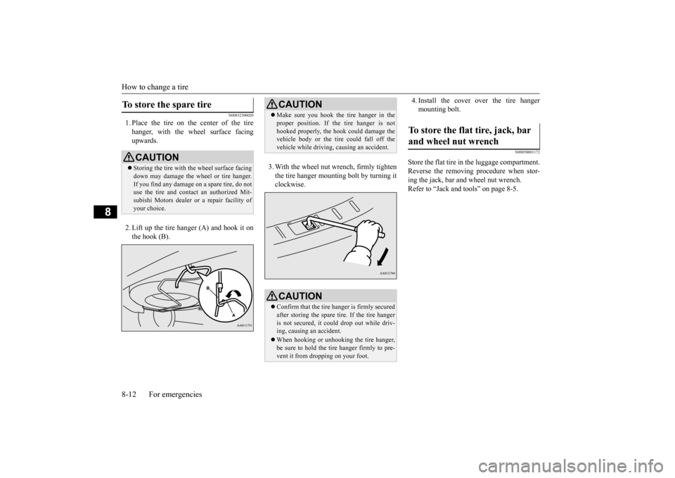
1. Place the tire on the center of the tire hanger, with the wheel surface facing upwards. 2. Lift up the tire hanger (A) and hook it on the hook (B).
3. With the wheel nut wrench, firmly tighten the tire hanger mounti
ng bolt by turning it
clockwise.
4. Install the cover over the tire hanger mounting bolt.
N00850001172
Store the flat tire in the luggage compartment.Reverse the removing procedure when stor- ing the jack, bar and wheel nut wrench. Refer to “Jack and t
ools” on page 8-5.
To store the spare tire
CAUTIONStoring the tire with the wheel surface facing down may damage the wheel or tire hanger. If you find any damage
on a spare tire, do not
use the tire and contact an authorized Mit- subishi Motors dealer or a repair facility of your choice.
CAUTION Make sure you hook the tire hanger in the proper position. If the tire hanger is nothooked properly, the hook
could damage the
vehicle body or the tire
could fall off the
vehicle while driving,
causing an accident.
CAUTIONConfirm that the tire hanger is firmly secured after storing the spare
tire. If the tire hanger
is not secured, it c
ould drop out while driv-
ing, causing
an accident.
When hooking or unhooking the tire hanger, be sure to hold the tire hanger firmly to pre-vent it from dropping on your foot.
To store the flat tire, jack, bar and wheel nut wrench
BK0211800US.book 12 ページ 2014年3月12日 水曜日 午後2時42分
Page 413 of 446

Replacement of light bulbs 9-32 Vehicle care and maintenance
9
N00950401656
N00901801131
1. When replacing the bulb on the left side of the vehicle, remo
ve the bolt (A) hold-
ing down the relay box and move the relay box toward the rear of the vehicle. (if so equipped)
2. Turn the cap (B) counterclockwise to remove it. 3. Turn the socket (C) counterclockwise to remove it, and then pull the bulb out of the socket. 4. To install the bulb, perform the removal steps in reverse.
Inside
Item
Wattage
1 - Cargo room light 8 W 2 - Dome light (rear) 8 W 3 -
Dome light (front)/Read- ing light
8 W
4 - Downlight – 5 - Vanity mirror lights 2 W 6 - Glove compartment light 1.4 W
NOTE
The downlight uses an LED instead of the bulb. Check with an
authorized Mitsubishi
Motors dealer or a re
pair facility of your
choice when the light needs to be repaired or replaced.
Headlights (low beam, except for vehicles equipped with high intensity discharge head- lights)/Daytime running lights
(if so equipped) * - Front of the vehicle
*- Front of the vehicle
BK0211800US.book 32 ページ 2014年3月12日 水曜日 午後2時42分
Page 414 of 446

Replacement of light bulbs
Vehicle care and maintenance 9-33
9
N00900301139
Do not attempt to disass
emble or repair head-
lights, and do not attempt to replace their bulbs.
N00901901099
1. Turn the cap (A) counterclockwise toremove it.
2. Turn the bulb (B) counterclockwise to remove it and then while holding down the tab (C), pull out the connector (D). 3. To install the bulb, perform the removal steps in reverse.
N00943201359
The alignment of the headlights should be checked by an authorized Mitsubishi Motors dealer or a repair fa
cility of your choice.
N00915501171
1. When replacing the bulb on the left side of the vehicle, move the relay box toward the rear of the vehicle. (if so equipped) (Refer to “Headlight
(low beam, except
for vehicles equipped with high intensity discharge headlights)/Daytime running light): Step 1” on page 9-32.2. Turn the socket (A
) counterclockwise to
remove it, and then pull the bulb out of the socket.
Headlights (low beam, for vehi- cles equipped with high inten-sity discharge headlights)
WA R N I N G A high voltage is present in the power cir- cuit and in the bulbs and bulb terminals. To avoid the risk of an electric shock, con-tact an authorized
Mitsubishi Motors
dealer whenever repair or replacement is necessary.
Headlights (high beam)
* - Front of the vehicle * - Front of the vehicle
Headlight aim adjustment Front side-marker lights
BK0211800US.book 33 ページ 2014年3月12日 水曜日 午後2時42分
Page 415 of 446

Replacement of light bulbs 9-34 Vehicle care and maintenance
9
3. To install the bulb, perform the removal steps in reverse.
N00917301577
When replacing the bulb on the left side ofthe vehicle, move the relay box toward the rear of the vehicle. (if so equipped)
(Refer to “Headlight (low beam, except for vehicles equipped with
high intensity dis-
charge headlights)/Daytime running light): Step 1” on page 9-32.) 1. Turn the cap (A) counterclockwise to remove it. 2. Pull out the socket (B), and then pull the bulb out of the socket.
3. To install the bulb, perform the removal steps in reverse. 1. Turn the socket (A) counterclockwise to remove it, and then pull the bulb out ofthe socket.
* - Front of the vehicle
Parking lights
Except for vehicles equipped with high intensity discharge headlights *: Front of the vehicle
Vehicles equipped with high inten-sity discharge headlights
BK0211800US.book 34 ページ 2014年3月12日 水曜日 午後2時42分