2015 MITSUBISHI OUTLANDER III ignition
[x] Cancel search: ignitionPage 371 of 446
How to change a tire 8-6 For emergencies
8
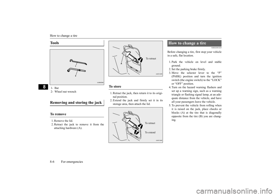
1. Remove the lid. 2. Retract the jack to remove it from theattaching hardware (A).
1. Retract the jack, then return it to its origi- nal position.2. Extend the jack and firmly set it in its storage area, then attach the lid.
N00836901829
Before changing a tire, first stop your vehiclein a safe, flat location. 1. Park the vehicle on level and stable ground.2. Set the parking brake firmly. 3. Move the selector
lever to the “P”
(PARK) position and turn the ignition switch (the engine switch) to the “LOCK” or “OFF” position.4. Turn on the hazard warning flashers and set up a warning sign, such as a warning triangle or flashing signal lamp, at an ade-quate distance from the vehicle, and have all your passengers leave the vehicle. 5. To prevent the vehicle from rolling whenit is raised on the jack, place chocks or blocks (A) at the ti
re that is diagonally
opposite from the tire (B) you are chang-ing.
Tools 1- Bar 2- Wheel nut wrenchRemoving and storing the jack To r e m o v e
To s t o r e
To retractTo r e t r a c t To e x t e n d
How to change a tire
BK0211800US.book 6 ページ 2014年3月12日 水曜日 午後2時42分
Page 380 of 446
Operation under adverse driving conditions
For emergencies 8-15
8
Release the parking brake. Set the selector lever to the “N” (NEUTRAL) position.
N00837201760
If your vehicle becomes
stuck in snow, sand,
or mud, it can often be moved by a rocking motion. Rock your vehicle back and forth to free it.Do not rev the engine or spin the wheels. Constant efforts to free a stuck vehicle can cause overheating and tr
ansaxle failure. Let
the engine idle for a few minutes to cool the transaxle before trying again. If your vehicle is still
stuck after several rock-
ing attempts, call for a commercial tow truck service.
[For front-wheel driv
e vehicle equipped with
the active stability control (ASC)]If the vehicle is towed with the ignitionswitch in the “ON” pos
ition or the operation
mode in ON and only the front wheels raised off the ground (Type C), the ASC may oper-ate, resulting in an accident. When towing the vehicle with the front wheels raised, keep the ignition switch or
the operation mode as
follows. [Except for vehicles equipped with the F. A . S . T. - k e y ]The ignition switch is in “LOCK”, “OFF” or “ACC” position. [Vehicles equipped with the F.A.S.T.-key]The operation mode is in OFF or ACC.
Towing a front-wheel drive vehi- cle with front wheels off the ground (Type C)
CAUTION
Operation under adverse driving conditions If your vehicle becomes stuck in sand, mud or snow
WA R N I N G When trying to rock
your vehicle out of a
stuck position, make sure that there are nopeople nearby. The
rocking motion can
make your vehicle suddenly lurch forward or backward, and inju
re any bystanders.
On wet roads
CAUTIONAvoid flooded roads. Water is often deeper than it looks, and you could be seriously hurtby driving into flood water. When driving in rain, on water-covered roads, or through a car
wash, water could get
into the brake discs and make them fail tem- porarily. In such cases, lightly press thebrake pedal to see if they are working prop- erly. If they are not, press the pedal lightly several times while driving to dry the brakepads or linings, then check them again. When driving in rain, a layer of water may form between the tires and the road surface (hydroplaning). This loosens your tires’ grip on the road, making it difficult to steer orbrake properly. When driving on a wet road:• Drive your vehicle at a safe speed.• Do not drive on worn tires.• Always keep the tires at the correct infla- tion pressures.
BK0211800US.book 15 ページ 2014年3月12日 水曜日 午後2時42分
Page 383 of 446
Service precautions 9-2 Vehicle care and maintenance
9
N00937301384
Taking regular care of your vehicle will pre- serve its value and appe
arance as long as pos-
sible. You can do some of the maintenance work yourself, and the rest should only be per- formed by an authorized Mitsubishi Motors dealer or a repair facility of your choice. If you discover a malfunction or other prob- lem, have it corrected by an authorized Mit-subishi Motors dealer or a repair facility of your choice. This section descri
bes the maintenance
inspections that you can do yourself, if you so desire. Follow the instructions and precau- tions for each procedure.
Have you purchased the Mitsubishi Motors Diamond Care Protection Plan? The Plansupplements your new
vehicle warranties.
See your authorized Mitsubishi Motors dealer for details.
N00937401457
The catalytic converter requires you to useunleaded fuel only. Leaded gasoline willdestroy the emission-control effectiveness of the converter. Normally, the
catalytic converter does not
require maintenance. Ho
wever, it is important
to keep the engine properly tuned for the con- verter to continue to work properly.
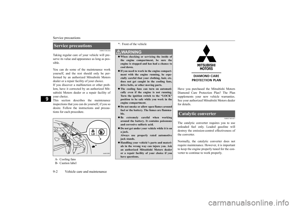
Service precautions A- Cooling fans B- Caution label
*: Front of the vehicleWA R N I N G When checking or servicing the inside of the engine compartment, be sure theengine is stopped and has had a chance to cool down. If you need to work
in the engine compart-
ment with the engine running, be espe- cially careful that your clothing, hair, etc.does not get caught in the cooling fans, drive belts, or other moving parts. The cooling fans can turn on automati- cally even if the engine is not running. Turn the ignition switch to the “LOCK”position to be safe while you work in the engine compartment. Do not smoke or allow open flames around fuel or the battery. The fumes are flamma- ble. Be extremely careful when working around the battery. It
contains poisonous
and corrosive sulfuric acid. Do not get under your ve
hicle while it is on
a jack. Always use properly rated automotive jack stands. Handling your vehicle’s parts and materi- als in the wrong way can injure you. Askan authorized Mitsub
ishi Motors dealer
or a repair facility of your choice if you have questions.
Catalytic converter
BK0211800US.book 2 ページ 2014年3月12日 水曜日 午後2時42分
Page 384 of 446
Engine hood
Vehicle care and maintenance 9-3
9
To reduce the possibili
ty of catalytic con-
verter damage: Use UNLEADED GASOLINE ONLY of the type of recommended in the “Fuel selection”. Do not drive with an extremely low fuel level. Running out of gas could damage the catalytic converter. Do not try to start the engine by pushing or towing the vehicle. If the battery is weak or run down, use jumper cables toproperly start the engine.
Do not idle the engine with any spark plug wires disconnected or removed, such aswhen performing
diagnosti
c tests.
Do not idle the engine
for a long time if it
is idling roughly or otherwise obviouslymalfunctioning. To prevent the catalytic converter from being damaged from unburned gas, do notrace the engine when turning off the igni- tion switch. Stop driving the vehicle if you think the performance is noticeably low, or the engine has a malfunction such as with theignition, etc. If you are not able to stop driving immediately,
slow down and drive
for only a short time. Have your vehiclechecked at an authorized Mitsubishi Motors dealer or a repair facility of your choice as soon
as possible.
In unusual situations involving major engine problems, a burning odor may indicate severe and abnormal catalyticconverter overheating.
If this occurs, stop
in a safe place, shut the engine off and let the vehicle cool. Once
the engine is cool,
immediately take your
vehicle to a dealer
or a repair facility of your choice for ser- vice.
N00937501559
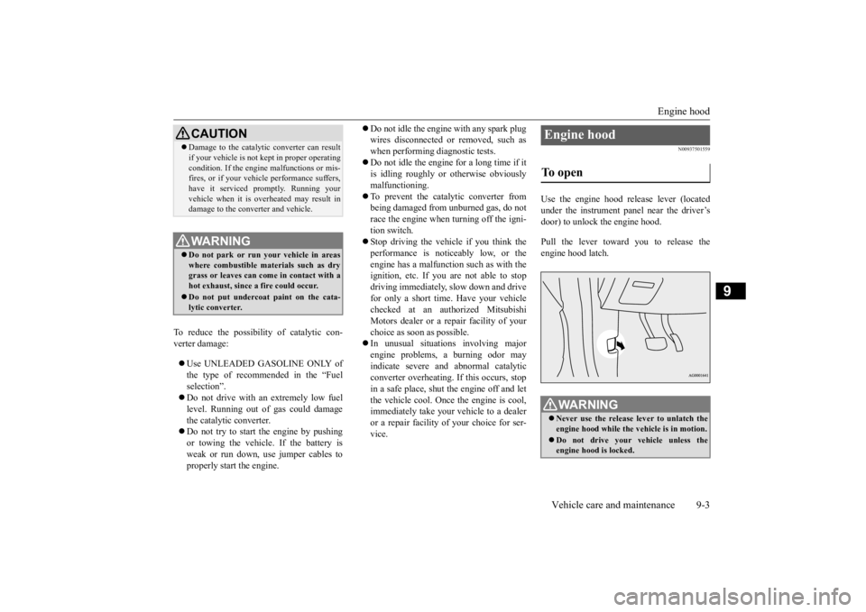
Use the engine hood release lever (located under the instrument panel near the driver’s door) to unlock the engine hood. Pull the lever toward you to release the engine hood latch.
CAUTION Damage to the catalyti
c converter can result
if your vehicle is not
kept in proper operating
condition. If the engine
malfunctions or mis-
fires, or if your vehi
cle performance suffers,
have it serviced promptly. Running your vehicle when it is
overheated may result in
damage to the converter and vehicle.WA R N I N G Do not park or run your vehicle in areas where combustible materials such as dry grass or leaves can come
in contact with a
hot exhaust, since a fire could occur. Do not put undercoat paint on the cata- lytic converter.
Engine hood To open
WA R N I N G Never use the release lever to unlatch the engine hood while the
vehicle is in motion.
Do not drive your vehicle unless the engine hood is locked.
BK0211800US.book 3 ページ 2014年3月12日 水曜日 午後2時42分
Page 404 of 446
General maintenance
Vehicle care and maintenance 9-23
9
N00950100050
Have the valve clea
rance checked at an
authorized Mitsubishi Motors dealer at the mileage specified in the “WARRANTY ANDMAINTENANCE MANUAL”. If the engine sounds abnormally loud, have adjustments made by an authorizedMitsubishi Motors dealer.
N00941300173
Check these regularly for damage or leaks inthe fuel lines and connections. Check the fuel tank filler cap for dama
ge or looseness. Pay
special attention to the fuel lines closest tohigh heat sources such
as the exhaust mani-
fold.
N00941400187
If the fuel-vapor vent line is clogged or dam- aged, the fuel-vapor mixture will escape, pol- luting the air. Have the system checked at an authorizedMitsubishi Motors dealer at the mileage spec- ified in the “WARRANTY AND MAINTE- NANCE MANUAL”.
N00941501299
The next pages list th
e maintenance service
recommended by Mitsubishi Motors Corpo- ration. In addition to the general maintenance that needs to be performed at the times listed,there are other parts which do not usually need regular maintenance. But, if any of these parts stops working prop-erly, your vehicle performance could suffer. Have these items checked if you notice a problem with them. If you have any questions, see your autho- rized Mitsubishi Motors
dealer for assistance.
N00941600059
Good brakes are essential for safe driving. Check the brake pads for wear. For good braking performance, replace the brake padswith the same type pa
ds as the originals.
N00941700076
Brake hoses and tubing should be checked for: Severe surface cracki
ng, scuffing or worn
spots. If the fabric casing of the hose isshowing through any cracks or worn spots in the rubber hose cover, the hose should be replaced. The brakes can fail if thehose wears through. Improper installation may cause twisting, or wheel, tire or
chassis interference.
N00941800093
Check the following parts for damage and grease leaks: Ball joint boots of the suspension and steering linkage Bellows on both ends of the drive shaft
Intake valve clearance Fuel system (tank, pipe line and connection, and fuel tank filler cap)
WA R N I N G If you see a fuel leak
or if you smell fuel,
do not run the engine. Any spark (includ-ing from the ignition
), flame or smoking
material could cause an explosion or fire. Call an authorized Mitsubishi Motorsdealer or a repair fa
cility of your choice
for assistance.
Evaporative emission control system (except evaporative emission canister) General maintenance
Disc brake pads Brake hoses Ball joint, steering linkage seals, drive shaft boots
BK0211800US.book 23 ページ 2014年3月12日 水曜日 午後2時42分
Page 407 of 446
Fuses 9-26 Vehicle care and maintenance
9
*: Fusible link Some fuses may not be installed on your vehicle, depending on the vehicle modelor specifications. The table above shows the main equip- ment corresponding to each fuse.
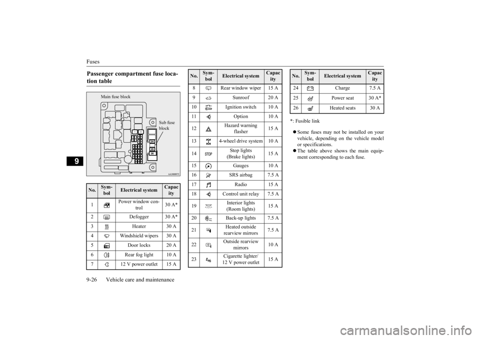
Passenger compartment fuse loca- tion table No.
Sym- bol
Electrical system
Capacity
1
Power window con-
trol
30 A*
2 Defogger 30 A* 3 Heater 30 A 4 Windshield wipers 30 A5 Door locks 20 A6 Rear fog light 10 A7 12 V power outlet 15 A
Sub fuse block
Main fuse block
8 Rear window wiper 15 A9 Sunroof 20 A 10 Ignition switch 10 A 11 Option 10 A 12
Hazard warning
flasher
15 A
13 4-wheel drive system 10 A 14
Stop lights (Brake lights)
15 A
15 Gauges 10 A 16 SRS airbag 7.5 A 17 Radio 15 A18 Control unit relay 7.5 A 19
Interior lights (Room lights)
15 A
20 Back-up lights 7.5 A 21
Heated outside rearview mirrors
7.5 A
22
Outside rearview
mirrors
10 A
23
Cigarette lighter/ 12 V power outlet
15 A
No.
Sym- bol
Electrical system
Capacity
24 Charge 7.5 A 25 Power seat 30 A*26 Heated seats 30 ANo.
Sym- bol
Electrical system
Capacity
BK0211800US.book 26 ページ 2014年3月12日 水曜日 午後2時42分
Page 408 of 446
Fuses
Vehicle care and maintenance 9-27
9
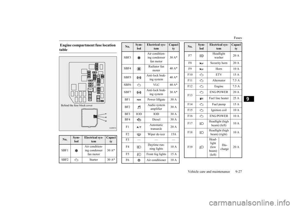
Engine compartment fuse location table No.
Sym- bol
Electrical sys-
tem
Capacity
SBF1
Air condition- ing condenser fan motor
30 A*
SBF2 Starter 30 A*Behind the fuse block cover
SBF3
Air condition- ing condenser fan motor
30 A*
SBF4
Radiator fan
motor
40 A*
SBF5
Anti-lock brak- ing system
40 A*
SBF6 VLC 40 A* SBF7
Anti-lock brak- ing system
30 A*
BF1 Power liftgate 30 A BF2
Audio system amplifier
30 A
BF3 IOD IOD 30 A BF4 Diesel 30 A F1
Automatic transaxle
20 A
F2 Wiper de-icer 15A F3 — — — F4
Daytime run- ning lights
10 A
F5 Front fog lights 15 A F6 Air conditioner 10 ANo.
Sym- bol
Electrical sys-
tem
Capacity
F7
Headlight washer
20 A
F8 Security horn 20 A F9 Horn 10 AF10 ETV 15 A F11 Alternator 7.5 A F12 Engine 7.5 A F13
ENG/POWER 20 A Fuel line heater 25 A
F14 Fuel pump 15 A F15 Ignition coil 10 A F16 ENG/POWER 10 A F17
Headlight (high beam) (left)
10 A
F18
Headlight (high beam) (right)
10 A
F19
Head- light (low beam) (left)
Dis- charge
20 A
No.
Sym- bol
Electrical sys-
tem
Capacity
BK0211800US.book 27 ページ 2014年3月12日 水曜日 午後2時42分
Page 409 of 446
Fuses 9-28 Vehicle care and maintenance
9
*: Fusible link Some fuses may not be installed on your vehicle, depending on the vehicle model or specifications. The table above shows the main equip- ment corresponding to each fuse.
The fuse block does not contain spare 7.5 A, 25 A or 30 A fuses. If one of these fusesburns out, substitute w
ith the following fuse.
7.5 A: 10 A spare fuse 25 A: 20 A spare fuse30 A: 30 A audio system amplifier fuse When using a substitute
fuse, replace with a
fuse of the correct capa
city as soon as possi-
ble.
N00954901141
1. Before replacing a fuse, always turn off the electrical item
connected to the fuse
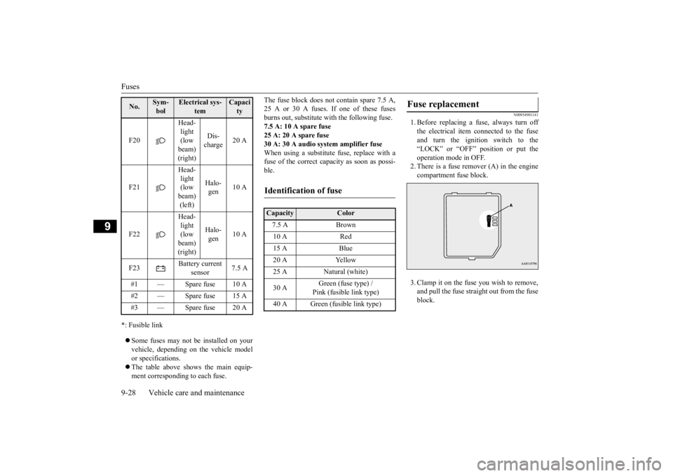
and turn the ignition switch to the“LOCK” or “OFF” position or put the operation mode in OFF. 2. There is a fuse remover (A) in the enginecompartment fuse block. 3. Clamp it on the fuse you wish to remove, and pull the fuse straight out from the fuseblock.
F20
Head- light (low beam) (right)
Dis- charge
20 A
F21
Head- light (low beam) (left)
Halo- gen
10 A
F22
Head- light (low beam) (right)
Halo- gen
10 A
F23
Battery current
sensor
7.5 A
#1 — Spare fuse 10 A #2 — Spare fuse 15 A #3 — Spare fuse 20 ANo.
Sym- bol
Electrical sys-
tem
Capacity
Identification of fuse Capacity
Color
7.5 A Brown 10 A Red 15 A Blue 20 A Yellow 25 A Natural (white) 30 A
Green (fuse type) / Pink (fusible link type)
40 A Green (fusible link type)
Fuse replacement
BK0211800US.book 28 ページ 2014年3月12日 水曜日 午後2時42分