2015 MINI COUPE ROADSTER CONVERTIBLE light
[x] Cancel search: lightPage 183 of 231
3.Insert the new bulb and attach the cover in
reverse order.
LED parking lights/LED fog lights/LED
daytime running lights
Follow the general instructions on lamps and
bulbs, refer to page 178.
Lights are implemented using LED technology.
Contact your service center in the event of a
malfunction.
Turn signals/parking lights/roadside
parking lights/fog lights/and daytime
running lights
Access to the bulbs via the wheel housing
Follow the general instructions on lamps and
bulbs, refer to page 178.
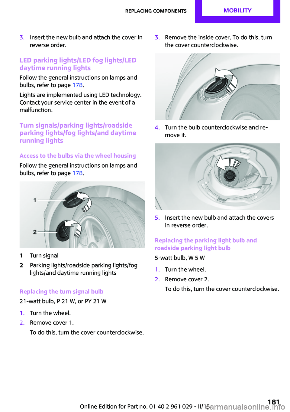
1Turn signal2Parking lights/roadside parking lights/fog
lights/and daytime running lights
Replacing the turn signal bulb
21-watt bulb, P 21 W, or PY 21 W
1.Turn the wheel.2.Remove cover 1.
To do this, turn the cover counterclockwise.3.Remove the inside cover. To do this, turn
the cover counterclockwise.4.Turn the bulb counterclockwise and re‐
move it.5.Insert the new bulb and attach the covers
in reverse order.
Replacing the parking light bulb and
roadside parking light bulb
5-watt bulb, W 5 W
1.Turn the wheel.2.Remove cover 2.
To do this, turn the cover counterclockwise.Seite 181Replacing componentsMOBILITY181
Online Edition for Part no. 01 40 2 961 029 - II/15
Page 184 of 231
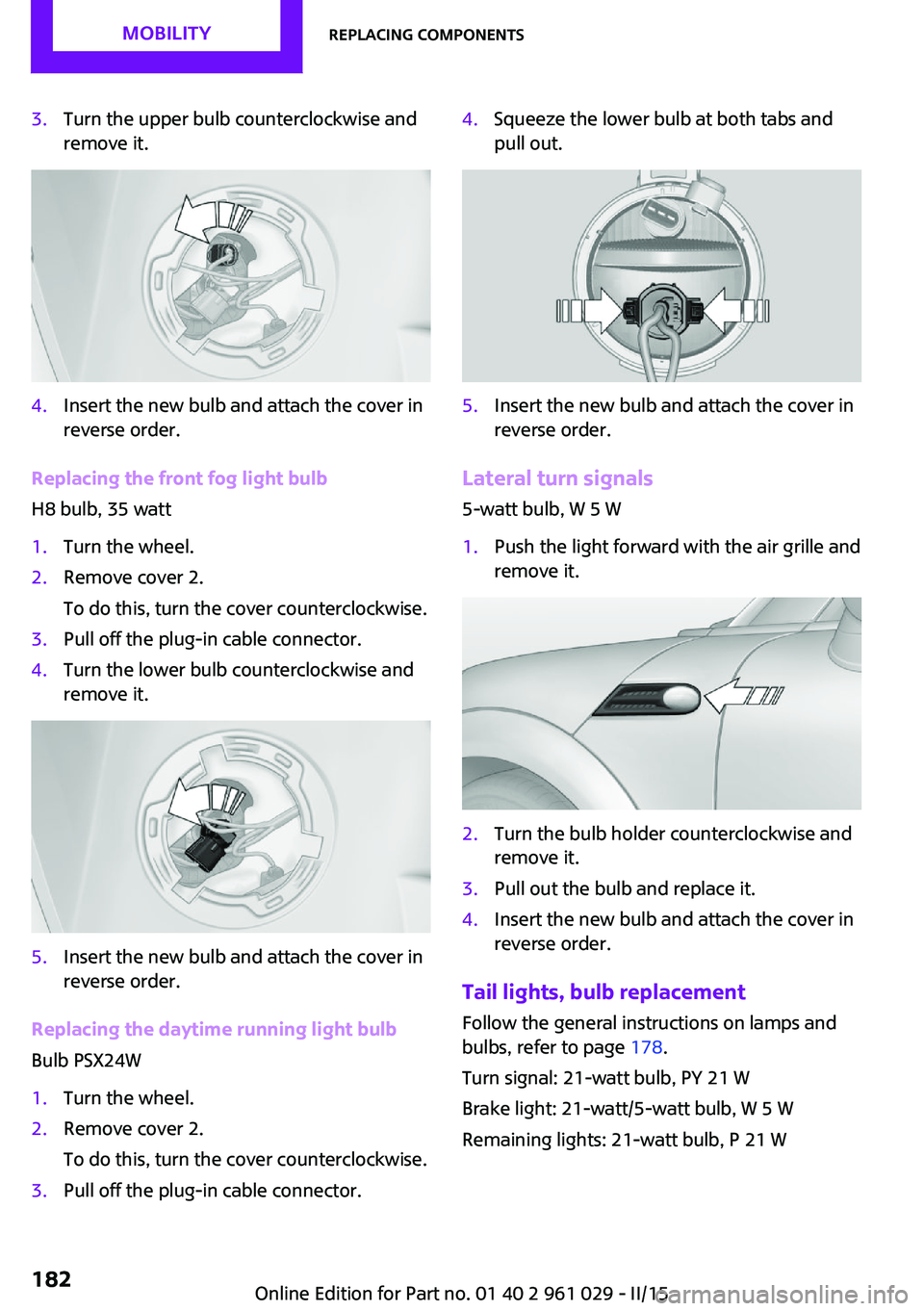
3.Turn the upper bulb counterclockwise and
remove it.4.Insert the new bulb and attach the cover in
reverse order.
Replacing the front fog light bulb
H8 bulb, 35 watt
1.Turn the wheel.2.Remove cover 2.
To do this, turn the cover counterclockwise.3.Pull off the plug-in cable connector.4.Turn the lower bulb counterclockwise and
remove it.5.Insert the new bulb and attach the cover in
reverse order.
Replacing the daytime running light bulb
Bulb PSX24W
1.Turn the wheel.2.Remove cover 2.
To do this, turn the cover counterclockwise.3.Pull off the plug-in cable connector.4.Squeeze the lower bulb at both tabs and
pull out.5.Insert the new bulb and attach the cover in
reverse order.
Lateral turn signals
5-watt bulb, W 5 W
1.Push the light forward with the air grille and
remove it.2.Turn the bulb holder counterclockwise and
remove it.3.Pull out the bulb and replace it.4.Insert the new bulb and attach the cover in
reverse order.
Tail lights, bulb replacement
Follow the general instructions on lamps and
bulbs, refer to page 178.
Turn signal: 21-watt bulb, PY 21 W
Brake light: 21-watt/5-watt bulb, W 5 W
Remaining lights: 21-watt bulb, P 21 W
Seite 182MOBILITYReplacing components182
Online Edition for Part no. 01 40 2 961 029 - II/15
Page 185 of 231
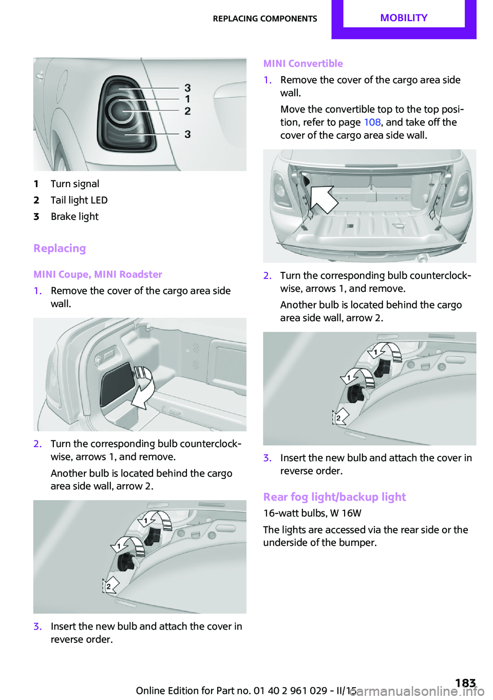
1Turn signal2Tail light LED3Brake light
Replacing
MINI Coupe, MINI Roadster
1.Remove the cover of the cargo area side
wall.2.Turn the corresponding bulb counterclock‐
wise, arrows 1, and remove.
Another bulb is located behind the cargo
area side wall, arrow 2.3.Insert the new bulb and attach the cover in
reverse order.MINI Convertible1.Remove the cover of the cargo area side
wall.
Move the convertible top to the top posi‐
tion, refer to page 108, and take off the
cover of the cargo area side wall.2.Turn the corresponding bulb counterclock‐
wise, arrows 1, and remove.
Another bulb is located behind the cargo
area side wall, arrow 2.3.Insert the new bulb and attach the cover in
reverse order.
Rear fog light/backup light
16-watt bulbs, W 16W
The lights are accessed via the rear side or the
underside of the bumper.
Seite 183Replacing componentsMOBILITY183
Online Edition for Part no. 01 40 2 961 029 - II/15
Page 186 of 231
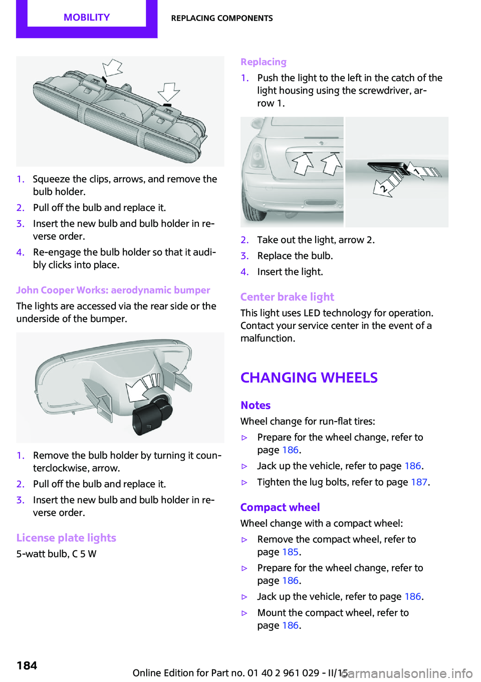
1.Squeeze the clips, arrows, and remove the
bulb holder.2.Pull off the bulb and replace it.3.Insert the new bulb and bulb holder in re‐
verse order.4.Re-engage the bulb holder so that it audi‐
bly clicks into place.
John Cooper Works: aerodynamic bumper
The lights are accessed via the rear side or the
underside of the bumper.
1.Remove the bulb holder by turning it coun‐
terclockwise, arrow.2.Pull off the bulb and replace it.3.Insert the new bulb and bulb holder in re‐
verse order.
License plate lights
5-watt bulb, C 5 W
Replacing1.Push the light to the left in the catch of the
light housing using the screwdriver, ar‐
row 1.2.Take out the light, arrow 2.3.Replace the bulb.4.Insert the light.
Center brake light
This light uses LED technology for operation.
Contact your service center in the event of a
malfunction.
Changing wheels NotesWheel change for run-flat tires:
▷Prepare for the wheel change, refer to
page 186.▷Jack up the vehicle, refer to page 186.▷Tighten the lug bolts, refer to page 187.
Compact wheel
Wheel change with a compact wheel:
▷Remove the compact wheel, refer to
page 185.▷Prepare for the wheel change, refer to
page 186.▷Jack up the vehicle, refer to page 186.▷Mount the compact wheel, refer to
page 186.Seite 184MOBILITYReplacing components184
Online Edition for Part no. 01 40 2 961 029 - II/15
Page 187 of 231
▷Tighten the lug bolts, refer to page 187.▷Drive with the compact wheel, refer to
page 185.
Removing the compact wheel
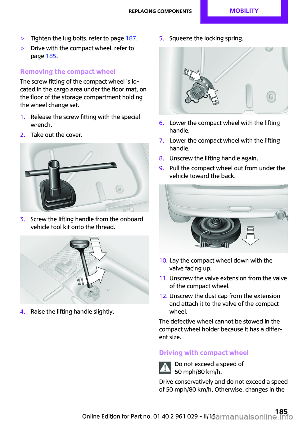
The screw fitting of the compact wheel is lo‐
cated in the cargo area under the floor mat, on
the floor of the storage compartment holding
the wheel change set.
1.Release the screw fitting with the special
wrench.2.Take out the cover.3.Screw the lifting handle from the onboard
vehicle tool kit onto the thread.4.Raise the lifting handle slightly.5.Squeeze the locking spring.6.Lower the compact wheel with the lifting
handle.7.Lower the compact wheel with the lifting
handle.8.Unscrew the lifting handle again.9.Pull the compact wheel out from under the
vehicle toward the back.10.Lay the compact wheel down with the
valve facing up.11.Unscrew the valve extension from the valve
of the compact wheel.12.Unscrew the dust cap from the extension
and attach it to the valve of the compact
wheel.
The defective wheel cannot be stowed in the
compact wheel holder because it has a differ‐
ent size.
Driving with compact wheel Do not exceed a speed of
50 mph/80 km/h.
Drive conservatively and do not exceed a speed
of 50 mph/80 km/h. Otherwise, changes in the
Seite 185Replacing componentsMOBILITY185
Online Edition for Part no. 01 40 2 961 029 - II/15
Page 193 of 231

the battery, or to the engine or body
ground of the vehicle to be started.
Body ground:
Starting the engine
Never use spray fluids to start the engine.
1.Start the engine of the assisting vehicle and
let it run for several minutes at a slightly in‐
creased idle speed.2.Start the engine of the vehicle being started
in the usual way.
If the first starting attempt is not successful,
wait a few minutes before making another
attempt in order to allow the discharged
battery to recharge.3.Let both engines run for several minutes.4.Disconnect the jumper cables in the reverse
order.
Check the battery and recharge if necessary.
Tow-starting and towing
Notes Observe applicable laws and regulations
Observe applicable laws and regulations
for tow-starting and towing. ◀
No additional passengers
Do not transport any passengers other
than the driver in a vehicle that is being
towed. ◀
Using a tow fitting
The screw-in tow fitting must always be carried
in the vehicle. It can be screwed in at the front
or rear of the MINI.
Tow fitting, information on use▷Use only the tow fitting provided with
the vehicle and screw it all the way in.▷Use the tow fitting for towing on paved
roads only.▷Avoid lateral loading of the tow fitting, e.g.,
do not lift the vehicle by the tow fitting.
Otherwise, damage to the tow fitting and the
vehicle can occur. ◀
Access to the screw thread Push out the tow fitting cover at the appropri‐
ate recess in the bumper.
Front
Rear
John Cooper Works with aerodynamic bumper:
Pull out the tow fitting cover in the bumper in
the lower section, arrow.
Seite 191Breakdown assistanceMOBILITY191
Online Edition for Part no. 01 40 2 961 029 - II/15
Page 194 of 231
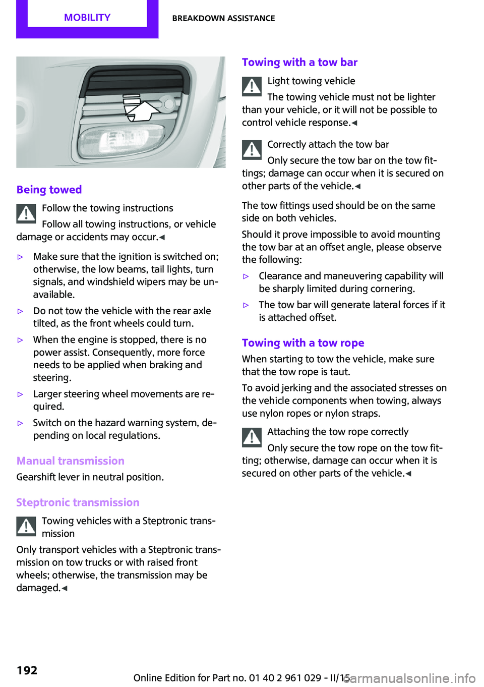
Being towedFollow the towing instructions
Follow all towing instructions, or vehicle
damage or accidents may occur. ◀
▷Make sure that the ignition is switched on;
otherwise, the low beams, tail lights, turn
signals, and windshield wipers may be un‐
available.▷Do not tow the vehicle with the rear axle
tilted, as the front wheels could turn.▷When the engine is stopped, there is no
power assist. Consequently, more force
needs to be applied when braking and
steering.▷Larger steering wheel movements are re‐
quired.▷Switch on the hazard warning system, de‐
pending on local regulations.
Manual transmission
Gearshift lever in neutral position.
Steptronic transmission Towing vehicles with a Steptronic trans‐
mission
Only transport vehicles with a Steptronic trans‐
mission on tow trucks or with raised front
wheels; otherwise, the transmission may be
damaged. ◀
Towing with a tow bar
Light towing vehicle
The towing vehicle must not be lighter
than your vehicle, or it will not be possible to
control vehicle response. ◀
Correctly attach the tow bar
Only secure the tow bar on the tow fit‐
tings; damage can occur when it is secured on
other parts of the vehicle. ◀
The tow fittings used should be on the same
side on both vehicles.
Should it prove impossible to avoid mounting
the tow bar at an offset angle, please observe
the following:▷Clearance and maneuvering capability will
be sharply limited during cornering.▷The tow bar will generate lateral forces if it
is attached offset.
Towing with a tow rope
When starting to tow the vehicle, make sure
that the tow rope is taut.
To avoid jerking and the associated stresses on
the vehicle components when towing, always
use nylon ropes or nylon straps.
Attaching the tow rope correctly
Only secure the tow rope on the tow fit‐
ting; otherwise, damage can occur when it is
secured on other parts of the vehicle. ◀
Seite 192MOBILITYBreakdown assistance192
Online Edition for Part no. 01 40 2 961 029 - II/15
Page 197 of 231

▷Remove additional attachments, for in‐
stance a spoiler or telephone antenna, if
there is a risk that these may be damaged.▷Insert the remote control into the ignition
lock.
Steptronic transmission
Before driving into the car wash, note the fol‐
lowing to ensure that the vehicle can roll:
1.Insert the remote control into the ignition
lock, even with Comfort Access.2.Move the selector lever to position N.3.Release the parking brake.4.Switch the engine off.5.Leave the remote control in the ignition
lock so that the vehicle can roll.
Hand car wash
If washing the vehicle by hand, use copious
quantities of water and car shampoo if neces‐
sary. Clean the vehicle with a sponge or a
washing brush by applying gentle pressure.
Before cleaning the windshield, deactivate the
rain sensor to avoid unintentional wiper activa‐
tion or switch off the ignition.
Adhere to the local regulations regarding
washing cars by hand.
Headlights Do not rub dry and do not use abrasive or caus‐
tic cleansers. Soak areas that have been soiled,
e.g., due to insects, with shampoo and rinse off
with copious quantities of water.
Thaw ice with a window deicer; do not use an
ice scraper.
Windows
Clean the outside and inside surfaces of the
windows and the mirror glasses with window
cleaner.
Do not clean mirror glass with cleaners contain‐
ing quartz.
Wiper blades
Clean with soapy water and replace regularly to
avoid streaking.
Wax and preservative residue and soiling on
the windows cause streaking during window
wiping and lead to premature wear on the
wiper blades and malfunctions of the rain sen‐
sor.
Vehicle care Car care products
Regular cleaning and care contributes signifi‐
cantly to vehicle value retention.
The manufacturer recommends using cleaning
and care products from MINI, since these have
been tested and approved.
Original MINI CareProducts have been tested
on materials, in the laboratory, and in the field,
and offer optimum care and protection for MINI
vehicles.
Do not use cleansers that contain alcohol
or solvents
Do not use cleansers that contain alcohol or
solvents, such as lacquer thinners, heavy-duty
grease removers, fuel, or such; this could lead
to surface damage. ◀
Car care and cleaning products
Follow the instructions on the container.
When cleaning the interior, open the doors or
windows.
Only use products intended for cleaning vehi‐
cles.
Cleansers can contain substances that are dan‐
gerous and harmful to your health. ◀Seite 195CareMOBILITY195
Online Edition for Part no. 01 40 2 961 029 - II/15