2015 MERCEDES-BENZ SLK-Class trunk release
[x] Cancel search: trunk releasePage 91 of 358

Opening and closing using the Smart-
Key
Important safety notes G
WARNING
When opening or closing the roof, body parts could be trapped by, for example, the roof
mechanism, trunk lid or side windows. There
is a risk of injury.
When raising or lowering the roof, make sure
that no body parts are in the vicinity of moving
components. If someone becomes trapped,
release the button.
Opening and closing X
Close the trunk partition (Y page 89).
X Close the trunk lid (Y page 80).
X Point the tip of the SmartKey at the driver's
door handle.
X To open: press and hold the 0036button
on the SmartKey until the roof is fully
opened.
The roof and the rear side windows open.
The front side windows close.
X To interrupt the opening procedure:
release the 0036button.
X To open the front side windows: press
and hold the 0036button on the SmartKey
again.
X To close: press and hold the 0037button
on the SmartKey until the roof is fully
closed.
The roof and the side windows close.
X To interrupt the closing procedure:
release the 0037button.
i When the roof is closed and the trunk par-
tition is open, the roof cannot be opened
using the SmartKey functions. Instead, all
of the side windows open or close simulta-
neously (Y page 84). Additionally, the
Trunk
Trunk Partition Partition Open
Openmessage appears
in the multifunction display. Locking the roof again
Important safety notes G
WARNING
If you do not fully open/close the soft top, the soft-top hydraulics depressurize after a short
time. This causes the soft top to lower unex-
pectedly and may cause you or others to be
trapped. There is a risk of injury.
Always open or close the soft top completely.
The roof is not locked if:
R the 0059 symbol and the Vario-Roof
Vario-Roof in in
Operation
Operation message appear in the multi-
function display.
R the 0059 symbol and the Open/Close
Open/Close
Vario-Roof Completely
Vario-Roof Completely message
appear and you hear a warning tone.
R you hear a warning tone for up to 10 sec-
onds when pulling away or while driving.
Locking You can lock the roof again if it is not locked
fully.
X Pull over and stop the vehicle safely as soon
as possible, paying attention to road and
traffic conditions.
X Make sure that the SmartKey is in position
2 in the ignition lock.
X Press the roof switch (Y page 88). Trunk partition
General notes !
To avoid damaging the roof or luggage
when folding back the roof, you should:
R only load the trunk to below the trunk
partition
R not place any objects on or in front of the
trunk partition Roof
89Opening and closing Z
Page 92 of 358

R
not place any objects on the cover
behind the roll bars
R not allow the cargo to push the trunk
partition upwards
The trunk partition can be used to cover lug-
gage and loads in the trunk.
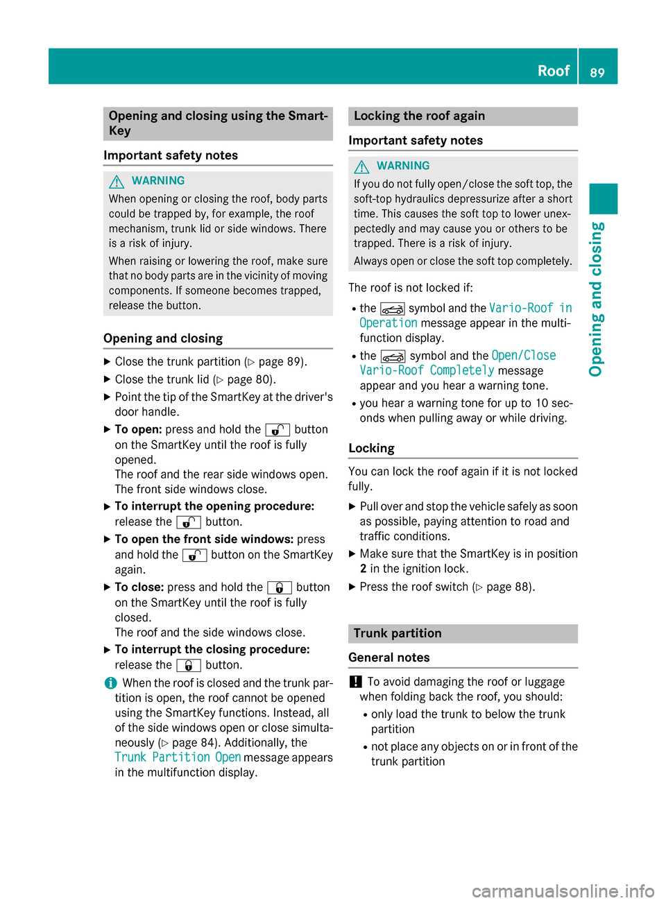
Opening and closing X
To close: pull back trunk partition 0043by
the handle in the direction of the arrow until
it engages on both sides in the eyelets on
the cargo compartment lip.
X To open: grip the handle of trunk parti-
tion 0043.
X Press the release button in the handle of
trunk partition 0043.
Trunk partition 0043is unlocked.
X Pull trunk partition 0043up out of the eyelets
on the cargo compartment lip.
X Push trunk partition 0043forwards against
the direction of the arrow by handle. Wind screen
Important safety notes G
WARNING
If you use the wind screen in darkness or in
other conditions offering poor visibility, your
view to the rear is further impaired. There is a
risk of an accident.
Only use the wind screen when visibility con-
ditions are good. G
WARNING
If the wind screen is incorrectly installed, it
could detach itself during a journey and
endanger other road users. There is a risk of
an accident and injury.
Install the wind screen as described.
! Install or remove the wind screen only
when the roof is open. You could otherwise
damage the wind screen or the vehicle inte-
rior.
The wind screen offers protection from the
wind when driving with the roof down.
The wind screen can be installed or removed from the driver's side or passenger side.
For operations involving the wind screen, it is
preferable to be positioned on the side of the vehicle facing away from the traffic, after
stopping the vehicle in accordance with the
traffic conditions.
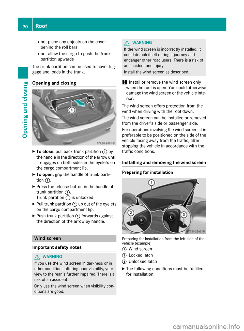
Installing and removing the wind screen Preparing for installation
Preparing for installation from the left side of the
vehicle (example)
0043 Wind screen
0044 Locked latch
0087 Unlocked latch
X The following conditions must be fulfilled
for installation: 90
RoofOpening and closing
Page 165 of 358

The function of the electric parking brake is
dependent on the on-board voltage. If the on-
board voltage is low or there is a malfunction in the system, it may not be possible to apply
the released parking brake.
X If this is the case, only park the vehicle on
level ground and secure it to prevent it roll-
ing away.
X Vehicles with automatic transmission:
shift the automatic transmission to posi-
tion P.
X Vehicles with manual transmission:
engage first gear.
It may not be possible to release an applied
parking brake if the on-board voltage is low or
there is a malfunction in the system. Contact a qualified specialist workshop.
i The electric parking brake performs a
function test at regular intervals while the
engine is switched off. The sounds that can
be heard while this is occurring are normal.
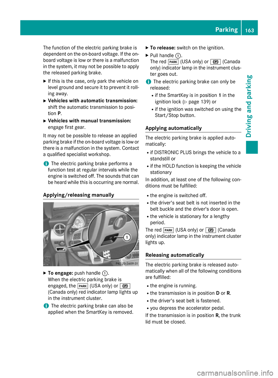
Applying/releasing manually X
To engage: push handle 0043.
When the electric parking brake is
engaged, the 0049(USA only) or 0024
(Canada only) red indicator lamp lights up
in the instrument cluster.
i The electric parking brake can also be
applied when the SmartKey is removed. X
To release: switch on the ignition.
X Pull handle 0043.
The red 0049(USA only) or 0024(Canada
only) indicator lamp in the instrument clus-
ter goes out.
i The electric parking brake can only be
released:
R if the SmartKey is in position 1in the
ignition lock (Y page 139) or
R if the ignition was switched on using the
Start/Stop button.
Applying automatically The electric parking brake is applied auto-
matically:
R if DISTRONIC PLUS brings the vehicle to a
standstill or
R if the HOLD function is keeping the vehicle
stationary
In addition, at least one of the following con-
ditions must be fulfilled:
R the engine is switched off.
R the driver's seat belt is not inserted in the
belt buckle and the driver's door is open.
R the vehicle is stationary for a lengthy
period.
The red 0049(USA only) or 0024(Canada
only) indicator lamp in the instrument cluster
lights up.
Releasing automatically The electric parking brake is released auto-
matically when all of the following conditions
are fulfilled:
R the engine is running.
R the transmission is in position Dor R.
R the driver's seat belt is fastened.
R you depress the accelerator pedal.
If the transmission is in position R, the trunk
lid must be closed. Parking
163Driving and parking Z
Page 309 of 358

The fuses are located in various fuse boxes:
R Fuse box in the engine compartment on the
left-hand side of the vehicle, when viewed
in the direction of travel
R Fuse box in the trunk
The fuse allocation chart is located in the
vehicle tool kit in the stowage compartment
under the trunk floor (Y page 292).Fuse box in the engine compartment
i Observe the "Important safety notes" sec-
tion (Y page 306). G
WARNING
When the hood is open and the windshield
wipers are set in motion, you can be injured by the wiper linkage. There is a risk of injury.
Always switch off the windshield wipers and
the ignition before opening the hood.
! Make sure that no moisture can enter the
fuse box when the cover is open.
! When closing the cover, make sure that it
is lying correctly on the fuse box. Moisture
seeping in or dirt could otherwise impair
the operation of the fuses. X
Make sure that the windshield wipers are
turned off.
X Open the hood.
X Use a dry cloth to remove any moisture
from the fuse box.
X To open: open clamp 0043.
X Remove fuse box cover 0044forwards. X
To close: check whether the seal is seated
correctly in cover 0044.
X Insert cover 0044at the rear of the fuse box
into the retainer.
X Fold down cover 0044and close clamps 0043.
X Close the hood. Fuse box in the trunk
i Observe the "Important safety notes" sec-
tion (Y page 306).
! Make sure that no moisture can enter the
fuse box when the cover is open. The fuse box is located in the trunk behind the
partition covering.
X Open the trunk lid.
X To open: release cover 0043on the right and
left-hand sides with a flat object.
X Open cover 0043downwards in the direction
of the arrow. Fuses
307Breakdown assistance Z
Page 344 of 358

Stowing the emergency spare wheel
! Only place the collapsible spare wheel in
the vehicle when it is dry. Otherwise, mois-
ture may get into the vehicle.
Take the following steps to stow a used col-
lapsible spare wheel. Otherwise, the collaps-
ible spare wheel will not fit in the trunk in the
intended manner. Mercedes-Benz recom-
mends that you have this work carried out at
a qualified specialist workshop.
X Unscrew the valve cap from the valve.
X If possible, unscrew the valve insert from
the valve and release the air.
i Fully deflating the tires can take a few
minutes.
X Screw the valve insert back into the valve.
X Screw the valve cap back on.
X Pull the protective sheet provided with the
spare wheel over the collapsible spare
wheel.
X Stow the collapsible spare wheel in the
emergency spare wheel well under the
trunk.
X Use the retaining screw to pierce the pro-
tective sheet and fasten the collapsible
spare wheel in place. Inflating the collapsible spare wheel
! Inflate the collapsible spare wheel using
the tire inflation compressor before lower-
ing the vehicle. The wheel rim could other-
wise be damaged.
! Do not operate the tire inflation compres-
sor for longer than ten minutes at a time
without a break. It may otherwise overheat.
The tire inflation compressor can be oper-
ated again once it has cooled down. X
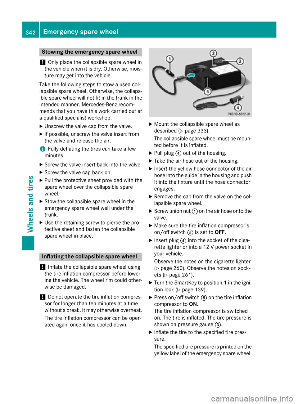
Mount the collapsible spare wheel as
described (Y page 333).
The collapsible spare wheel must be moun-
ted before it is inflated.
X Pull plug 0085out of the housing.
X Take the air hose out of the housing.
X Insert the yellow hose connector of the air
hose into the guide in the housing and push it into the fixture until the hose connector
engages.
X Remove the cap from the valve on the col-
lapsible spare wheel.
X Screw union nut 0043on the air hose onto the
valve.
X Make sure the tire inflation compressor's
on/off switch 0083is set to OFF.
X Insert plug 0085into the socket of the ciga-
rette lighter or into a 12 V power socket in your vehicle.
Observe the notes on the cigarette lighter
(Y page 260). Observe the notes on sock-
ets (Y page 261).
X Turn the SmartKey to position 1in the igni-
tion lock (Y page 139).
X Press on/off switch 0083on the tire inflation
compressor to ON.
The tire inflation compressor is switched
on. The tire is inflated. The tire pressure is
shown on pressure gauge 0087.
X Inflate the tire to the specified tire pres-
sure.
The specified tire pressure is printed on the
yellow label of the emergency spare wheel. 342
Emergency spare wheelWheels and tires