2015 MERCEDES-BENZ SLK-Class display
[x] Cancel search: displayPage 275 of 358
Before performing these steps, make sure
that new batteries have been installed in
garage door drive remote control 0083.
R Note that some remote controls only trans-
mit for a limited amount of time (the indi-
cator lamp on the remote control goes out).
Press button 0084on remote control 0083again
before transmission ends.
R Align the antenna cable of the garage door
opener unit. This can improve signal recep-tion/transmission.
Opening/closing the garage door After it has been programed, the integrated
garage door opener performs the function of
the garage door system remote control.
Please also read the operating instructions
for the garage door system.
X Turn the SmartKey to position 2in the igni-
tion lock (Y page 139).
X Press button 0044,0087or0085 which you have
programed to operate the garage door.
Garage door system with a fixed code: indi-
cator lamp 0043lights up green.
Garage door system with a rolling code:
indicator lamp 0043flashes green.
The transmitter will transmit a signal as long
as the button is pressed. The transmission is halted after a maximum of ten seconds and
indicator lamp 0043lights up yellow. Press but-
ton 0044, 0087or0085 again if necessary.
Clearing the memory Make sure that you clear the memory of the
integrated garage door opener before selling
the vehicle.
X Turn the SmartKey to position 2in the igni-
tion lock (Y page 139).
X Press and hold buttons 0044and 0085.
The indicator lamp initially lights up yellow
and then green.
X Release buttons 0044and 0085.
The memory of the integrated garage door
opener in the rear-view mirror is cleared. Compass
Calling up the compass Compass
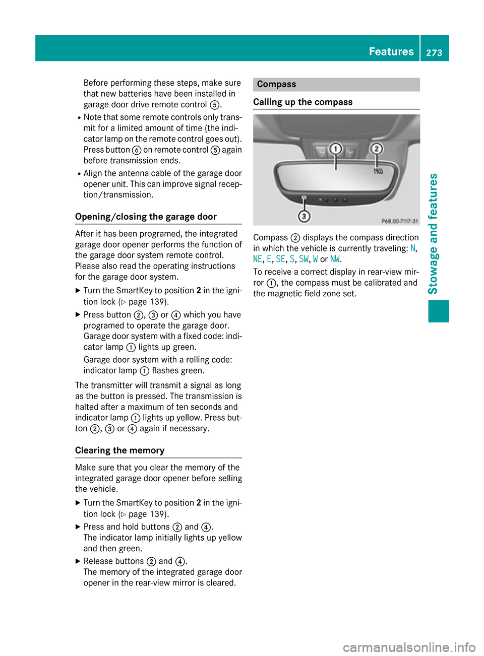
0044displays the compass direction
in which the vehicle is currently traveling: N N,
NE
NE, E
E,SE
SE, S
S, SW
SW, W
Wor NW
NW.
To receive a correct display in rear-view mir-
ror 0043, the compass must be calibrated and
the magnetic field zone set. Features
273Stowage and features Z
Page 276 of 358
Setting the compass
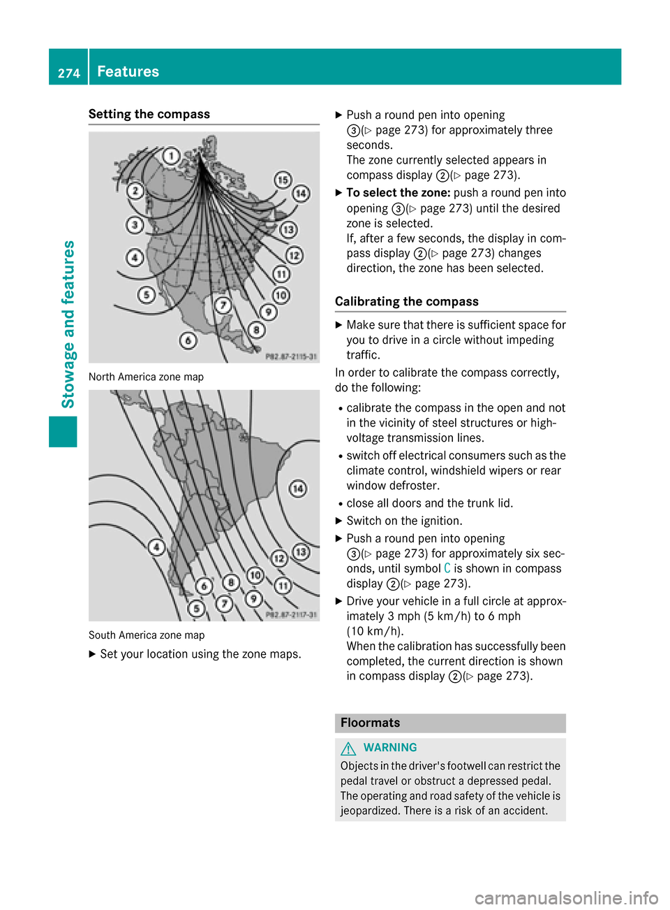
North America zone map
South America zone map
X Set your location using the zone maps. X
Push a round pen into opening
0087(Y page 273) for approximately three
seconds.
The zone currently selected appears in
compass display 0044(Ypage 273).
X To select the zone: push a round pen into
opening 0087(Ypage 273) until the desired
zone is selected.
If, after a few seconds, the display in com-
pass display 0044(Ypage 273) changes
direction, the zone has been selected.
Calibrating the compass X
Make sure that there is sufficient space for
you to drive in a circle without impeding
traffic.
In order to calibrate the compass correctly,
do the following:
R calibrate the compass in the open and not
in the vicinity of steel structures or high-
voltage transmission lines.
R switch off electrical consumers such as the
climate control, windshield wipers or rear
window defroster.
R close all doors and the trunk lid.
X Switch on the ignition.
X Push a round pen into opening
0087(Y page 273) for approximately six sec-
onds, until symbol C
C is shown in compass
display 0044(Ypage 273).
X Drive your vehicle in a full circle at approx-
imately 3 mph (5 km/h) to 6 mph
(10 km/h).
When the calibration has successfully been completed, the current direction is shown
in compass display 0044(Ypage 273). Floormats
G
WARNING
Objects in the driver's footwell can restrict the pedal travel or obstruct a depressed pedal.
The operating and road safety of the vehicle is
jeopardized. There is a risk of an accident. 274
FeaturesStowage and features
Page 283 of 358
X
Replace cap 0043on the filler neck and turn
clockwise.
Ensure that the cap locks into place
securely.
X Check the oil level again with the oil dip-
stick (Y page 279).
Further information on engine oil
(Y page 349). Checking and adding other service
products
Checking coolant level G
WARNING
Certain components in the engine compart-
ment, such as the engine, radiator and parts
of the exhaust system, can become very hot.
Working in the engine compartment poses a
risk of injury.
Where possible, let the engine cool down and touch only the components described in the
following. G
WARNING
The engine cooling system is pressurized, par- ticularly when the engine is warm. When
opening the cap, you could be scalded by hotcoolant spraying out. There is a risk of injury.
Let the engine cool down before opening the
cap. Wear eye and hand protection when
opening the cap. Open the cap slowly half a
turn to allow pressure to escape. Example X
Park the vehicle on a level surface.
Only check the coolant level when the vehi- cle is on a level surface and the engine has
cooled down.
X Turn the SmartKey to position 2in the igni-
tion lock (Y page 139).
On vehicles with KEYLESS-GO, press the
Start/Stop button twice (Y page 140).
X Check the coolant temperature gauge in
the multifunction display.
The coolant temperature must be below
158 ‡ (70 †).
X Turn the SmartKey to position
0(Y page 139) in the ignition lock.
X Slowly turn cap 0044half a turn counter-
clockwise to allow excess pressure to
escape.
X Turn cap 0044further counter-clockwise and
remove it.
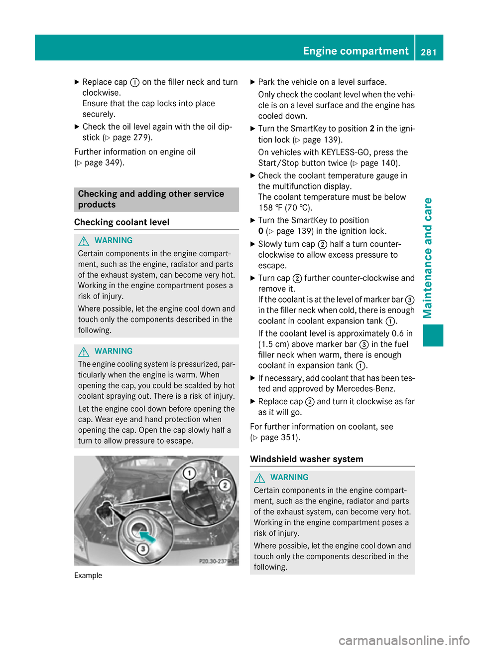
If the coolant is at the level of marker bar 0087
in the filler neck when cold, there is enough coolant in coolant expansion tank 0043.
If the coolant level is approximately 0.6 in
(1.5 cm) above marker bar 0087in the fuel
filler neck when warm, there is enough
coolant in expansion tank 0043.
X If necessary, add coolant that has been tes-
ted and approved by Mercedes-Benz.
X Replace cap 0044and turn it clockwise as far
as it will go.
For further information on coolant, see
(Y page 351).
Windshield washer system G
WARNING
Certain components in the engine compart-
ment, such as the engine, radiator and parts
of the exhaust system, can become very hot.
Working in the engine compartment poses a
risk of injury.
Where possible, let the engine cool down and touch only the components described in the
following. Engine compartment
281Maintenance and care Z
Page 284 of 358

G
WARNING
Windshield washer concentrate could ignite if it comes into contact with hot engine compo-
nents or the exhaust system. There is a risk of
fire and injury.
Make sure that no windshield washer con-
centrate is spilled next to the filler neck. Example
X To open: pull cap0043upwards by the tab.
X Add the premixed washer fluid.
X To close: press cap 0043onto the filler neck
until it engages.
If the washer fluid level drops below the rec-
ommended minimum of 1 liter, a message
appears in the multifunction display prompt-
ing you to add washer fluid (Y page 242).
Further information on windshield washer
fluid/antifreeze (Y page 352).ASSYST PLUS
Service messages
The ASSYST PLUS service interval display
informs you of the next service due date.
Information on the type of service and service
intervals (see the separate Maintenance
Booklet).
You can obtain further information from an
authorized Mercedes-Benz Center or at
http://www.mbusa.com (USA only).
i The ASSYST PLUS service interval display
does not show any information on the engine oil level. Observe the notes on the
engine oil level (Y
page 279).
The multifunction display shows a service
message for several seconds, e.g.:
R Service A in .. Days Service A in .. Days
R Service A Due
Service A Due
R Service A Exceeded by .. Days
Service A Exceeded by .. Days
Depending on the operating conditions of the vehicle, the remaining time or distance until
the next service due date is displayed.
The letter A Aor B
B, possibly in connection with a
number or another letter, shows the type of
service. A Astands for a minor service and B
Bfor
a major service.
You can obtain further information from an
authorized Mercedes-Benz Center.
The ASSYST PLUS service interval display
does not take into account any periods of
time during which the battery is disconnec-
ted.
Maintaining the time-dependent service
schedule:
X Note down the service due date displayed
in the multifunction display before discon-
necting the battery.
or
X After reconnecting the battery, subtract
the battery disconnection periods from the
service date shown on the display. Hiding a service message
X Press the 0076or0038 button on the steer-
ing wheel. 282
ASSYST PLUSMaintenance and care
Page 285 of 358
Displaying service messages
X Switch on the ignition.
X Press the 0059or0065 button on the steer-
ing wheel to select the Serv. Serv.menu.
X Press the 0063or0064 button to select the
ASSYST PLUS
ASSYST PLUS submenu and confirm by
pressing the 0076button.
The service due date appears in the multi-
function display. Information about Service
Resetting the ASSYST PLUS service
interval display !
If the ASSYST PLUS service interval dis-
play has been inadvertently reset, this set-
ting can be corrected at a qualified special-
ist workshop.
Have service work carried out as described in the Maintenance Booklet. This may oth-
erwise lead to increased wear and damage
to the major assemblies or the vehicle.
A qualified specialist workshop, e.g. an
authorized Mercedes-Benz Center, will reset
the ASSYST PLUS service interval display
after the service work has been carried out.
You can also obtain further information on
maintenance work, for example.
Special service requirements The specified maintenance interval takes only
the normal operation of the vehicle into
account. Under arduous operating conditions
or increased load on the vehicle, mainte-
nance work must be carried out more fre-
quently, for example:
R regular city driving with frequent intermedi-
ate stops
R if the vehicle is primarily used to travel
short distances R
use in mountainous terrain or on poor road
surfaces
R if the engine is often left idling for long peri-
ods
Under these or similar conditions, have, for
example, the air filter, engine oil and oil filter
replaced or changed more frequently. Under
arduous operating conditions, the tires must
be checked more often. Further information
can be obtained at a qualified specialist work- shop, e.g. an authorized Mercedes-Benz Cen-
ter.
Driving abroad An extensive Mercedes-Benz Service network
is also available in other countries. You can
obtain further information from any author-
ized Mercedes-Benz Center. Care
Notes on care
H
Environmental note
Dispose of empty packaging and cleaning
cloths in an environmentally responsible man- ner.
! For cleaning your vehicle, do not use any
of the following:
R dry, rough or hard cloths
R abrasive cleaning agents
R solvents
R cleaning agents containing solvents
Do not scrub.
Do not touch the surfaces or protective
films with hard objects, e.g. a ring or ice
scraper. You could otherwise scratch or
damage the surfaces and protective film.
! Do not park the vehicle for an extended
period straight after cleaning it, particularly after having cleaned the wheels with wheel
cleaner. Wheel cleaners could cause
increased corrosion of the brake discs and brake pads/linings. For this reason, you Care
283Maintenance and care Z
Page 290 of 358
X
Clean the exhaust pipe with a chrome care
product tested and approved by Mercedes-
Benz.
Impurities combined with the effects of road
grit and corrosive environmental factors may
cause flash rust to form on the surface. You
can restore the original shine of the exhaust
pipe by cleaning it regularly, especially in win- ter and after washing. Interior care
Cleaning the display !
For cleaning, do not use any of the fol-
lowing:
R alcohol-based thinner or gasoline
R abrasive cleaning agents
R commercially-available household clean-
ing agents
These may damage the display surface. Do not put pressure on the display surface
when cleaning. This could lead to irrepara-
ble damage to the display.
X Before cleaning the display, make sure that
it is switched off and has cooled down.
X Clean the display surface using a commer-
cially available microfiber cloth and
TFT/LCD display cleaner.
X Dry the display surface using a dry micro-
fiber cloth.
Cleaning the plastic trim G
WARNING
Care products and cleaning agents containing solvents cause surfaces in the cockpit to
become porous. As a result, plastic parts may
come loose in the event of air bag deploy-
ment. There is a risk of injury.
Do not use any care products and cleaning
agents to clean the cockpit. !
Do not affix the following to plastic surfa-
ces:
R stickers
R films
R scented oil bottles or similar items
You can otherwise damage the plastic.
! Do not allow cosmetics, insect repellent
or sunscreen to come into contact with the
plastic trim. This maintains the high-quality look of the surfaces.
X Wipe the plastic trim with a damp, lint-free
cloth, e.g. a microfiber cloth.
X Heavy soiling: use car care and cleaning
products recommended and approved by
Mercedes-Benz.
The surface may change color temporarily.
Wait until the surface is dry again.
Cleaning the steering wheel and gear or selector lever X
Thoroughly wipe with a damp cloth or use
leather care agents that have been recom- mended and approved by Mercedes-Benz.
Cleaning genuine wood and trim ele-
ments !
Do not use solvent-based cleaning agents
such as tar remover, wheel cleaners, pol-
ishes or waxes. There is otherwise a risk of
damaging the surface.
! Do not use chrome polish on trim pieces.
The trim pieces have a chrome look but are mostly made of anodized aluminum and
can lose their shine if chrome polish is
used. Use a damp, lint-free cloth instead
when cleaning the trim pieces.
If the chrome-plated trim pieces are very
dirty, you can use a chrome polish. If you
are unsure as to whether the trim pieces
are chrome-plated or not, consult an
authorized Mercedes-Benz Center. 288
CareMaintenance and care
Page 295 of 358
X
If possible, bring the front wheels into the
straight-ahead position.
X Switch off the engine.
X Vehicles without KEYLESS-GO: remove
the SmartKey from the ignition lock.
X Vehicles with KEYLESS-GO: open the
driver's door.
The on-board electronics now have status
0. This is the same as the SmartKey having
been removed.
X Vehicles with KEYLESS-GO: remove the
Start/Stop button from the ignition lock
(Y page 140).
X All occupants must get out of the vehicle.
Make sure that they are not endangered as they do so.
X Make sure that no one is near the danger
area while a wheel is being changed. Any-
one who is not directly assisting in the
wheel change should, for example, stand
behind the barrier.
X Get out of the vehicle. Pay attention to traf-
fic conditions when doing so.
X Close the driver's door. MOExtended tires (tires with run-flat
properties)
General notes With MOExtended tires (tires with run flat
characteristics), you can continue to drive
your vehicle even if there is a total loss of
pressure in one or more tires. The affected
tire must not show any clearly visible damage.
You can recognize MOExtended tires by the
MOExtended marking which appears on the
sidewall of the tire. You will find this marking next to the tire size designation, the load-
bearing capacity and the speed index
(Y page 326).
MOExtended tires may only be used in con-
junction with an active tire pressure loss
warning system or with an active tire pressure
monitor. If the pressure loss warning message
appears in the multifunction display:
R Observe the instructions in the display
messages (Y page 236).
R Check the tire for damage.
R If driving on, observe the following notes.
The maximum driving distance is approx-
imately 50 miles (80 km) when the vehicle is
partially laden and approximately 18 miles
(30 km) when the vehicle is fully laden.
In addition to the vehicle load, the driving dis- tance possible depends upon:
R Speed
R Road condition
R Outside temperature
The driving distance possible in run-flat mode may be reduced by extreme driving condi-
tions/maneuvers, or it can be increased
through a moderate style of driving.
The maximum permissible distance which
can be driven in run-flat mode is counted fromthe moment the tire pressure loss warning
appears in the multifunction display.
You must not exceed a maximum speed of
50 mph (80 km/h).
i When replacing one or all tires, make sure
that you use only tires:
R of the size specified for the vehicle and
R marked "MOExtended"
If a tire has gone flat and cannot be
replaced with a MOExtended tire, a stand-
ard tire may be used as a temporary meas-
ure. Make sure that you use the proper size and type (summer or winter tire).
i Vehicles equipped with MOExtended tires
are not equipped with a TIREFIT kit at the
factory. It is therefore recommended that
you additionally equip your vehicle with a
TIREFIT kit if you mount tires that do not
feature run-flat properties, e.g. winter tires. A TIREFIT kit is available, for example, from
a qualified specialist workshop. Flat tire
293Breakdown assistance
Page 319 of 358
when adjusting the tire pressure
(Y
page 314).
i The actual values for tires are vehicle-
specific and may deviate from the values in
the illustration. Checking the tire pressures
Important safety notes Observe the notes on tire pressure
(Y
page 314).
Information on air pressure for the tires on
your vehicle can be found:
R on the vehicle's Tire and Loading Informa-
tion placard on the B-pillar
R on the tire pressure label on the fuel filler
flap
R in the "Tire pressure" section
Checking tire pressures manually To determine and set the correct tire pres-
sure, proceed as follows:
X Remove the valve cap of the tire that is to
be checked.
X Press the tire pressure gauge securely onto
the valve.
X Read the tire pressure and compare it with
the recommended value on the Tire and
Loading Information placard (Y page 314).
X If the tire pressure is too low, increase it to
the recommended value.
X If the tire pressure is too high, release air by
pressing down the metal pin in the valve.
Use the tip of a pen, for example. Then,
check the tire pressure again using the tire
pressure gauge.
X Screw the valve cap onto the valve.
X Repeat these steps for the other tires. Tire pressure loss warning system
(Canada only)
General notes While the vehicle is in motion, the tire pres-
sure loss warning system monitors the set
tire pressure using the rotational speed of the wheels. This enables the system to detect
significant pressure loss in a tire. If the speed
of rotation of a wheel changes as a result of a loss of pressure, a corresponding warning
message will appear in the multifunction dis- play.
You can recognize the tire pressure loss warn-
ing by the Run Flat Indicator Active Run Flat Indicator Active
Press 'OK' to Restart
Press 'OK' to Restart message which
appears in the Service
Servicemenu of the multi-
function display. Information on the message
display can be found in the "Restarting the tire
pressure loss warning system" section
(Y page 318).
Important safety notes The tire pressure warning system does not
warn you of an incorrectly set tire pressure.
Observe the notes on the recommended tire
pressure (Y page 314).
The tire pressure loss warning does not
replace the need to regularly check the tire
pressure. An even loss of pressure on several tires at the same time cannot be detected by
the tire pressure loss warning system.
The tire pressure monitor is not able to warn
you of a sudden loss of pressure, e.g. if the
tire is penetrated by a foreign object. In the
event of a sudden loss of pressure, bring the
vehicle to a halt by braking carefully. Avoid
abrupt steering maneuvers.
The function of the tire pressure loss warning system is limited or delayed if:
R snow chains are mounted on your vehicle's
tires.
R road conditions are wintry.
R you are driving on sand or gravel. Tire pressure
317Wheels and tires Z