2015 MERCEDES-BENZ S-COUPE warning light
[x] Cancel search: warning lightPage 202 of 286
A malfunction in the system has been detec-
ted if one of the following occurs:
R The indicator lamp in the SOS button does
not come on during the system self-test.
R The indicator lamp in the FRoadside
Assistance button does not light up during
self-diagnosis of the system.
R The indicator lamp in the ïMB Info call
button does not light up during self-diag-
nosis of the system.
R The indicator lamp in one or more of the
following buttons continues to light up red
after the system self-diagnosis:
- SOS button
- F Roadside Assistance call button
- ï MB Info call button
R The
Inoperativeor theService Not
Activatedmessage appears in the multi-
function display after the system self-diag-
nosis.
If a malfunction is indicated as outlined
above, the system may not operate as expec-
ted. In the event of an emergency, help will
have to be summoned by other means.
Have the system checked at the nearest
authorized Mercedes-Benz Center or contact the following service hotlines:
Mercedes-Benz Customer Assistance Center
at 1-800-FOR-MERCede s (1-800-367-6372)
or 1-866-990-9007
Emergency call
Important safety notes
GWARNING
It can be dangerous to remain in the vehicle,
even if you have pressed the SOS button in an emergency if:
R you see smoke inside or outside of the vehi-
cle, e.g. if there is a fire after an accident
R the vehicle is on a dangerous section of
road
R the vehicle is not visible or cannot easily be
seen by other road users, particularly whendark or in poor visibility conditions
There is a risk of an accident and injury.
Leave the vehicle immediately in this or simi-
lar situations as soon as it is safe to do so.
Move to a safe location along with other vehi-
cle occupants. In such situations, secure the
vehicle in accordance with national regula-
tions, e. g. with a warning triangle.
General notes
Observe the notes on system activation ( Y page 199).
An emergency call is dialed automatically if an
air bag or Emergency Tensioning Device is
triggered. You cannot end an automatically
triggered emergency call yourself.
An emergency call can also be initiated man- ually.
As soon as the emergency call has been ini-
tiated, the indicator lamp in the SOS button
flashes. The
Connecting Callmessage
appears in the multifunction display.
The audio output is muted.
Once the connection has been made, the
Call Connectedmessage appears in the
multifunction display.
200Features
Sto wage an d features
Page 206 of 286
USA: FCC ID: CB2HMIHL4
Canada: IC: 279B-HMIHL4
Important safety notes
GWARNING
When you operate or program the garage doorwith the integrated garage door opener, per-
sons in the range of movement of the garage
door can become trapped or struck by the
garage door. There is a risk of injury.
When using the integrated garage door
opener, always make sure that nobody is
within the range of movement of the garagedoor.
GWARNING
Combustion engines emit poisonous exhaust
gases such as carbon monoxide. Inhaling
these exhaust gases leads to poisoning. There is a risk of fatal injury. Therefore never leave
the engine running in enclosed spaces with-
out sufficient ventilation.
Programming
Programming buttons
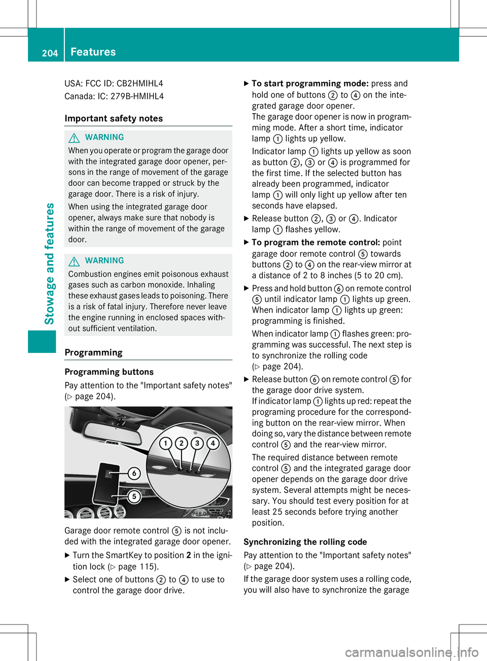
Pay attention to the "Important safety notes"
( Y page 204).
Garage door remote control Ais not inclu-
ded with the integrated garage door opener.
X Turn the SmartKey to position 2in the igni-
tion lock ( Ypage 115).
X Select one of buttons ;to? to use to
control the garage door drive. X
To start programming mode: press and
hold one of buttons ;to? on the inte-
grated garage door opener.
The garage door opener is now in program-
ming mode. After a short time, indicatorlamp :lights up yellow.
Indicator lamp :lights up yellow as soon
as button ;,= or? is programmed for
the first time. If the selected button has
already been programmed, indicatorlamp :will only light up yellow after ten
seconds have elapsed.
X Release button ;,= or? . Indicator
lamp :flashes yellow.
X To program the remote control: point
garage door remote control Atowards
buttons ;to? on the rear-view mirror at
a distance of 2 to 8 inches (5 to 20 cm).
X Press and hold button Bon remote control
A until indicator lamp :lights up green.
When indicator lamp :lights up green:
programming is finished.
When indicator lamp :flashes green: pro-
gramming was successful. The next step is to synchronize the rolling code ( Y page 204).
X Release button Bon remote control Afor
the garage door drive system.
If indicator lamp :lights up red: repeat the
programing procedure for the correspond-
ing button on the rear-view mirror. When
doing so, vary the distance between remote control Aand the rear-view mirror.
The required distance between remote
control Aand the integrated garage door
opener depends on the garage door drive
system. Several attempts might be neces-
sary. You should test every position for at
least 25 seconds before trying anotherposition.
Synchronizing the rolling code
Pay attention to the "Important safety notes"
( Y page 204).
If the garage door system uses a rolling code,
you will also have to synchronize the garage
204Features
Stowage and features
Page 208 of 286
Problems when programming
If you are experiencing problems programing
the integrated garage door opener on the
rear-view mirror, take note of the following
instructions:
R Check the transmitter frequency used by
garage door drive remote control Aand
whether it is supported. The transmitter
frequency can usually be found on the back
of the garage door drive remote control.
The integrated garage door opener is com-
patible with devices that have units which
operate in the frequency range of 280 to
433 MHz.
R Replace the batteries in garage door
remote control A. This increases the like-
lihood that garage door remote control A
will transmit a strong and precise signal to
the integrated garage door opener.
R When programming, hold remote controlA at varying distances and angles from the
button which you are programming. Try var- ious angles at a distance between 2and
12 inches (5to 30 cm) or at the same angle
but at varying distances.
R If another remote control is available for the
same garage door drive, repeat the same
programming steps with this remote con-
trol. Before performing these steps, make
sure that new batteries have been installed
in garage door drive remote control A.
R Note that some remote controls only trans-
mit for a limited amount of time (the indi-
cator lamp on the remote control goes out).
Press button Bon remote control Aagain
before transmission ends.
R Align the antenna cable of the garage door
opener unit. This can improve signal recep-tion/transmission.
Opening/closing the garage door
After it has been programmed, the integrated
garage door opener performs the function of
the garage door system remote control. Please also read the operating instructions
for the garage door system.
X Turn the SmartKey to position 2in the igni-
tion lock ( Ypage 115).
X Press button ;,= or? which you have
programmed to operate the garage door.
Garage door system with a fixed code: indi-
cator lamp :lights up green.
Garage door system with a rolling code:
indicator lamp :flashes green.
The transmitter will transmit a signal as
long as the button is pressed. The trans-
mission is halted after a maximum of ten
seconds and indicator lamp :lights up
yellow.
X Press button ;,= or? again if neces-
sary.
Clearing the memory
Make sure that you clear the memory of the
integrated garage door opener before selling
the vehicle.
X Turn the SmartKey to position 2in the igni-
tion lock ( Ypage 115).
X Press and hold buttons ;and ?.
The indicator lamp initially lights up yellow
and then green.
X Release buttons ;and ?.
The memory of the integrated garage door
opener in the rear-view mirror is cleared.
Floormats
GWARNING
Objects in the driver's footwell can restrict the pedal travel or obstruct a depressed pedal.
The operating and road safety of the vehicle is
jeopardized. There is a risk of an accident.
Make sure that all objects in the vehicle are
stowed correctly, and that they cannot enter
the driver's footwell. Install the floormats
securely and as specified in order to ensure
sufficient clearance for the pedals. Do not use
206Features
Stowage and features
Page 213 of 286
!Make sure that the windshield wipers are
not folded away from the windshield. You
could otherwise damage the windshield
wipers or the hood.
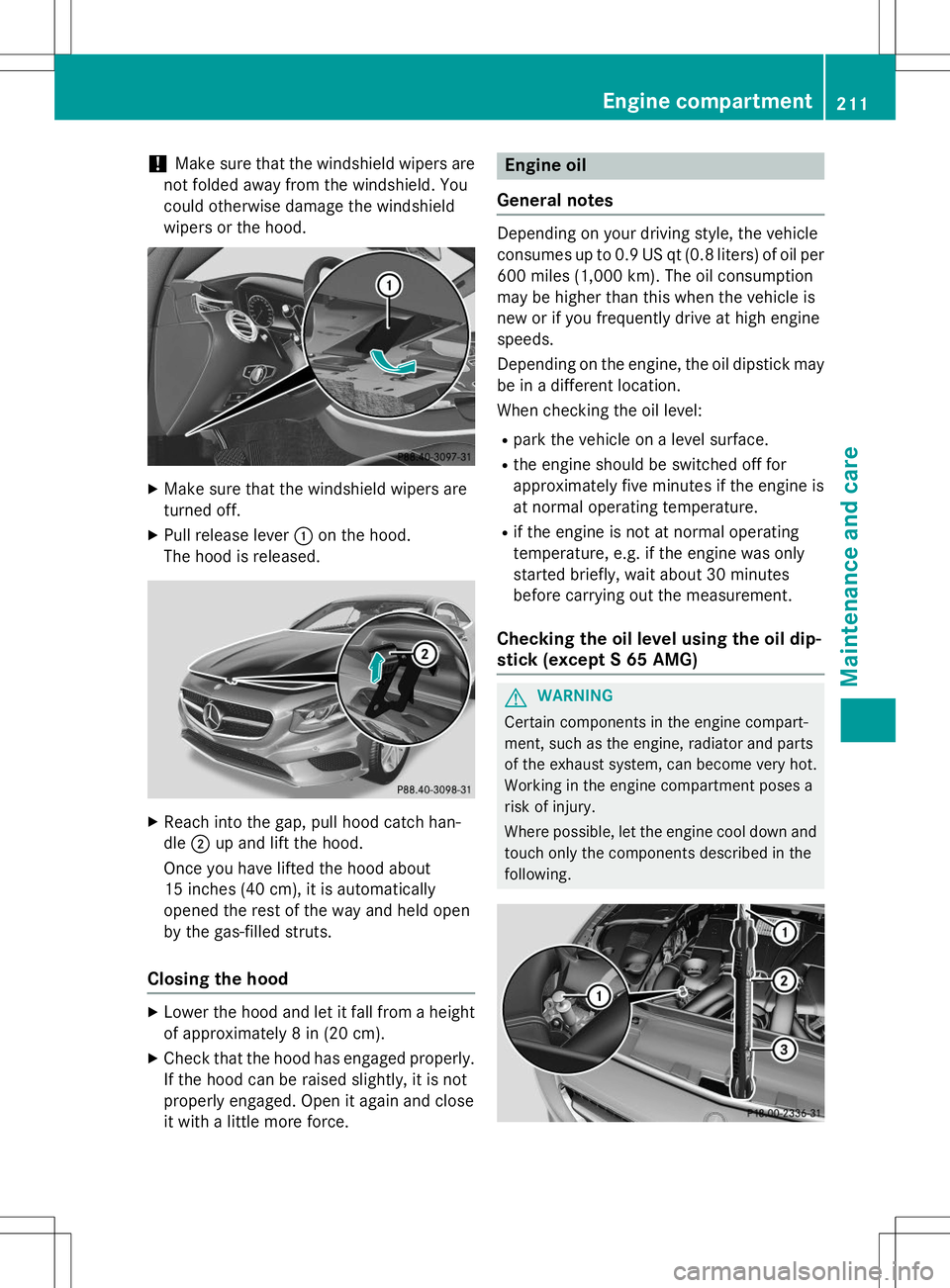
X Make sure that the windshield wipers are
turned off.
X Pull release lever :on the hood.
The hood is released.
X Reach into the gap, pull hood catch han- dle ;up and lift the hood.
Once you have lifted the hood about
15 inches (40 cm), it is automatically
opened the rest of the way and held open
by the gas-filled struts.
Closing the hood
X Lower the hood and let it fall from a height
of approximately 8 in (20 cm).
X Check that the hood has engaged properly.
If the hood can be raised slightly, it is not
properly engaged. Open it again and close
it with a little more force.
Engine oil
General notes
Depending on your driving style, the vehicle
consumes up to 0.9 US qt (0.8 liters) of oil per 600 miles (1,000 km). The oil consumption
may be higher than this when the vehicle is
new or if you frequently drive at high enginespeeds.
Depending on the engine, the oil dipstick maybe in a different location.
When checking the oil level:
R park the vehicle on a level surface.
R the engine should be switched off for
approximately five minutes if the engine is
at normal operating temperature.
R if the engine is not at normal operating
temperature, e.g. if the engine was only
started briefly, wait about 30 minutes
before carrying out the measurement.
Checking the oil level using the oil dip-
stick (except S 65 AMG)
GWARNING
Certain components in the engine compart-
ment, such as the engine, radiator and parts
of the exhaust system, can become very hot.
Working in the engine compartment poses a
risk of injury.
Where possible, let the engine cool down and
touch only the components described in the
following.
Engine compartment211
Maintenance and care
Z
Page 227 of 286
XWhen the tire pressure is correct, unscrew
the filler hose from the valve of the sealed tire.
X Screw the valve cap onto the tire valve of
the sealed tire.
X Pull the tire sealant bottle out of the tire
inflation compressor.
The filler hose remains attached to the tire
sealant bottle.
X Stow the tire sealant bottle and the tire
inflation compressor.
X Drive to the nearest qualified specialist
workshop and have the tire changed there.
X Have the tire sealant bottle replaced as
soon as possible at a qualified specialistworkshop.
X Have the tire sealant bottle replaced every
four years at a qualified specialist work-shop.
Battery (vehicle)
Important safety notes
Special tools and expert knowledge are
required when working on the battery, e.g.
removal and installation. You should there-
fore have all work involving the battery car-
ried out at a qualified specialist workshop.
GWARNING
Work carried out incorrectly on the battery
can lead, for example, to a short circuit and
thus damage the vehicle electronics. This canlead to function restrictions applying to
safety-relevant systems, e.g. the lighting sys-
tem, ABS (anti-lock braking system) or ESP ®
(Electronic Stability Program). The operating
safety of your vehicle may be restricted. You
could lose control of the vehicle, for example:
R braking
R in the event of abrupt steering maneuver
and/or when the vehicle's speed is not
adapted to the road conditions
There is a risk of an accident.
In the event of a short circuit or a similar inci- dent, contact a qualified specialist workshop
immediately. Do not drive any further. You
should have all work involving the battery car-
ried out at a qualified specialist workshop.
iFor further information about ABS and
ESP ®
, see ( Ypage 66) and ( Ypage 71).
All vehicles except AMG vehicles:
GWARNING
Electrostatic build-up can lead to the creation of sparks, which could ignite the highly explo-
sive gases of a battery. There is a risk of an explosion.
Before handling the battery, touch the vehicle body to remove any existing electrostatic build-up.
The highly flammable gas mixture forms when
charging the battery as well as when jump-
starting.
Always make sure that neither you nor the
battery is electrostatically charged. A build-
up of electrostatic charge can be caused, for
example:
R by wearing clothing made from syntheticfibers
R due to friction between clothing and seats
R if you push or pull the battery across the
carpet or other synthetic materials
R if you wipe the battery with a cloth
GWARNING
During the charging process, a battery produ-
ces hydrogen gas. If a short circuit occurs or
sparks are created, the hydrogen gas can
ignite. There is a risk of an explosion.
R Make sure that the positive terminal of a
connected battery does not come into con-
tact with vehicle parts.
R Never place metal objects or tools on a bat-
tery.
R It is important that you observe the descri-
bed order of the battery terminals when
connecting and disconnecting a battery.
Battery (vehicle)225
Roadside Assistance
Z
Page 230 of 286
Benz vehicles and tested and approved by
Mercedes-Benz is available as an accessory.
It permits the charging of the battery in its
installed position. Contact an authorized
Mercedes-Benz Center for further informa-
tion and availability. Read the battery charg-
er's operating instructions before charging
the battery.
All vehicles except AMG vehicles:if the
indicator/warning lamps in the instrument
cluster do not light up at low temperatures, it is very likely that the discharged battery has
frozen. In this case you may neither jump-
start the vehicle nor charge the battery. The
service life of a thawed-out battery may be
shorter. The starting characteristics can be
impaired, particularly at low temperatures.
Have the thawed-out battery checked at a
qualified specialist workshop.
AMG vehicles: at low temperatures, do not
charge a battery which has been removed
using a battery charger. Allow the battery to
warm up gently first, if necessary. Otherwise,
the service life can be shortened and the
starting characteristics impaired, especially
at low temperatures.
228Battery (vehicle)
Roadside Assistance
Page 231 of 286
Jump-starting
For the jump-starting procedure, use only the jump-starting connection point, consisting of apositive terminal and a ground point, in the engine compartment.
All vehicles except AMG vehicles:
GWARNING
Battery acid is caustic. There is a risk of injury.
Avoid contact with skin, eyes or clothing. Do not inhale any battery gases. Do not lean over the
battery. Keep children away from batteries. Wash away battery acid immediately with plenty of
clean water and seek medical attention.
GWARNING
During charging and jump-starting, explosive gases can escape from the battery. There is a risk of an explosion.
Particularly avoid fire, open flames, creating sparks and smoking. Ensure there is sufficient ven-
tilation while charging and jump-starting. Do not lean over a battery.
GWARNING
During the charging process, a battery produces hydrogen gas. If a short circuit occurs or sparks
are created, the hydrogen gas can ignite. There is a risk of an explosion.
R Make sure that the positive terminal of a connected battery does not come into contact with
vehicle parts.
R Never place metal objects or tools on a battery.
R It is important that you observe the described order of the battery terminals when connecting
and disconnecting a battery.
R When jump-starting, make sure that the battery poles with identical polarity are connected.
R It is particularly important to observe the described order when connecting and disconnecting
the jumper cables.
R Never connect or disconnect the battery terminals while the engine is running.
GWARNING
A discharged battery can freeze at temperatures below freezing point. When jump-starting the
vehicle or charging the battery, gases can escape from the battery. There is a risk of an explosion.
Allow the frozen battery to thaw out before charging it or jump-starting.
!Avoid repeated and lengthy starting attempts. Otherwise, the catalytic converter could be
damaged by the non-combusted fuel.
If, at low temperatures, the indicator lamps/warning lamps in the instrument cluster do not
light up, it is highly likely that the discharged battery has frozen. In this case, you may neither
charge the battery nor jump-start the vehicle. The service life of a thawed-out battery may be
shorter. The starting characteristics can be impaired, particularly at low temperatures. Have
the thawed-out battery checked at a qualified specialist workshop.
All vehicles:
Jump-starting229
Roadside Assistance
Z
Page 246 of 286
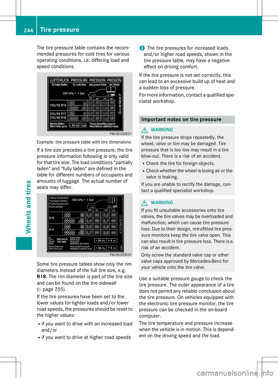
The tire pressure table contains the recom-
mended pressures for cold tires for various
operating conditions, i.e. differing load and
speed conditions.
Example: tire pressure table with tire dimensions
If a tire size precedes a tire pressure, the tirepressure information following is only valid
for that tire size. The load conditions "partially
laden" and "fully laden" are defined in the
table for different numbers of occupants and
amounts of luggage. The actual number of
seats may differ.
Some tire pressure tables show only the rim
diameters instead of the full tire size, e.g.R18 . The rim diameter is part of the tire size
and can be found on the tire sidewall( Y page 255).
If the tire pressures have been set to the
lower values for lighter loads and/or lower
road speeds, the pressures should be reset to the higher values:
R if you want to drive with an increased loadand/or
R if you want to drive at higher road speeds
iThe tire pressures for increased loads
and/or higher road speeds, shown in the
tire pressure table, may have a negative
effect on driving comfort.
If the tire pressure is not set correctly, this
can lead to an excessive build up of heat and a sudden loss of pressure.
For more information, contact a qualified spe-
cialist workshop.
Important notes on tire pressure
GWARNING
If the tire pressure drops repeatedly, the
wheel, valve or tire may be damaged. Tire
pressure that is too low may result in a tire
blow-out. There is a risk of an accident.
R Check the tire for foreign objects.
R Check whether the wheel is losing air or the
valve is leaking.
If you are unable to rectify the damage, con-
tact a qualified specialist workshop.
GWARNING
If you fit unsuitable accessories onto tire
valves, the tire valves may be overloaded and malfunction, which can cause tire pressure
loss. Due to their design, retrofitted tire pres- sure monitors keep the tire valve open. This
can also result in tire pressure loss. There is a
risk of an accident.
Only screw the standard valve cap or other
valve caps approved by Mercedes-Benz for
your vehicle onto the tire valve.
Use a suitable pressure gauge to check the
tire pressure. The outer appearance of a tire
does not permit any reliable conclusion about the tire pressure. On vehicles equipped with
the electronic tire pressure monitor, the tire
pressure can be checked in the on-board
computer.
The tire temperature and pressure increase
when the vehicle is in motion. This is depend-
ent on the driving speed and the load.
244Tire pressure
Wheels and tires