2015 MERCEDES-BENZ M-Class Page 53
[x] Cancel search: Page 53Page 385 of 466

X
Lift the cargo compartment floor up
(Y page 344).
X Remove "Minispare" emergency spare
wheel (Y page 441). Flat tire
Preparing the vehicle
Your vehicle may be equipped with: R MOExtended tires (tires with run-flat prop-
erties) (Y page 383)
Vehicle preparation is not necessary on
vehicles with MOExtended tires.
R a TIREFIT kit (Y page 382)
R an emergency spare wheel (only for certain
countries) (Y page 440)
Information on changing/mounting a wheel
(Y page 423).
X Stop the vehicle on solid, non-slippery and
level ground, as far away as possible from
traffic.
X Switch on the hazard warning lamps.
X Secure the vehicle against rolling away
(Y page 182).
X If possible, bring the front wheels into the
straight-ahead position.
X Vehicles with the AIRMATIC package:
make sure that highway level is selected
(Y page 211).
X Switch off the engine.
X Vehicles without KEYLESS-GO: remove
the SmartKey from the ignition lock.
X Vehicles with KEYLESS-GO: open the
driver's door.
The on-board electronics now have status
0. This is the same as the SmartKey having been removed.
X Vehicles with KEYLESS-GO: remove the
Start/Stop button from the ignition lock
(Y page 158).
X All occupants must get out of the vehicle.
Make sure that they are not endangered as they do so. X
Make sure that no one is near the danger
area while a wheel is being changed. Any-
one who is not directly assisting in the
wheel change should, for example, stand
behind the barrier.
X Get out of the vehicle. Pay attention to traf-
fic conditions when doing so.
X Close the driver's door.
X Unload heavy luggage.
i Only operate the tire inflation compressor
using a 12 V socket, even if the ignition is
turned off (Y page 349).
An emergency cut-out ensures that the on- board voltage does not drop too low. If the on-board voltage is too low, the power to
the sockets is automatically cut. This
ensures that there is sufficient power to
start the engine. MOExtended tires (tires with run-flat
properties)
General notes With MOExtended tires (tires with run flat
characteristics), you can continue to drive
your vehicle even if there is a total loss of
pressure in one or more tires. The affected
tire must not show any clearly visible damage.
You can recognize MOExtended tires by the
MOExtended marking which appears on the
sidewall of the tire. You will find this marking
next to the tire size designation, the load-
bearing capacity and the speed index
(Y page 417).
MOExtended tires may only be used in con-
junction with an active tire pressure loss
warning system or with an active tire pressure
monitor.
If the pressure loss warning message
appears in the multifunction display:
R Observe the instructions in the display
messages (Y page 312).
R Check the tire for damage.
R If driving on, observe the following notes. Flat tire
383Breakdown assistance
Page 387 of 466

inhale TIREFIT fumes. Keep tire sealant away
from children. There is a risk of injury.
If you come into contact with the tire sealant, observe the following:
R Rinse off the tire sealant from your skin
immediately with water.
R If the tire sealant comes into contact with
your eyes, immediately rinse them thor-
oughly with clean water.
R If tire sealant is swallowed, immediately
rinse your mouth out thoroughly and drink
plenty of water. Do not induce vomiting,
and seek medical attention immediately.
R Immediately change out of clothing which
has come into contact with tire sealant.
R If an allergic reaction occurs, seek medical
attention immediately.
! Do not operate the tire inflation compres-
sor for longer than eight minutes at a time
without a break. It may otherwise overheat.
The tire inflation compressor can be oper-
ated again once it has cooled down.
Comply with the manufacturer’s safety
instructions on the sticker on the tire inflation
compressor.
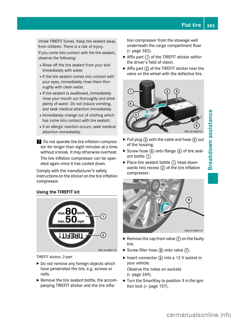
Using the TIREFIT kit TIREFIT sticker, 2-part
X Do not remove any foreign objects which
have penetrated the tire, e.g. screws or
nails.
X Remove the tire sealant bottle, the accom-
panying TIREFIT sticker and the tire infla- tion compressor from the stowage well
underneath the cargo compartment floor
(Y
page 382).
X Affix part 0043of the TIREFIT sticker within
the driver's field of vision.
X Affix part 0044of the TIREFIT sticker near the
valve on the wheel with the defective tire. X
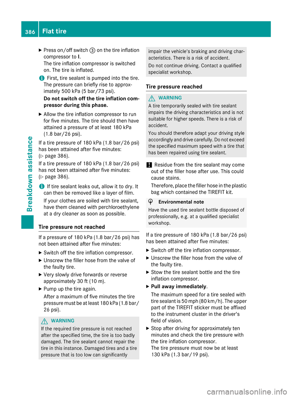
Pull plug 0085with the cable and hose 0083out
of the housing.
X Screw hose 0083onto flange 0084of tire seal-
ant bottle 0043.
X Place tire sealant bottle 0043head down-
wards into recess 0044of the tire inflation
compressor. X
Remove the cap from valve 006Bon the faulty
tire.
X Screw filler hose 006Conto valve 006B.
X Insert connector 0085into a 12 V socket in
your vehicle.
Observe the notes on sockets
(Y page 349).
X Turn the SmartKey to position 1in the igni-
tion lock (Y page 157). Flat tire
385Breakdown assistance Z
Page 388 of 466

X
Press on/off switch 0087on the tire inflation
compressor to I.
The tire inflation compressor is switched
on. The tire is inflated.
i First, tire sealant is pumped into the tire.
The pressure can briefly rise to approx-
imately 500 kPa (5 bar/73 psi).
Do not switch off the tire inflation com-
pressor during this phase.
X Allow the tire inflation compressor to run
for five minutes. The tire should then have
attained a pressure of at least 180 kPa
(1.8 bar/26 psi).
If a tire pressure of 180 kPa (1.8 bar/26 psi) has been attained after five minutes:
(Y page 386).
If a tire pressure of 180 kPa (1.8 bar/26 psi) has not been attained after five minutes:
(Y page 386).
i If tire sealant leaks out, allow it to dry. It
can then be removed like a layer of film.
If your clothes are soiled with tire sealant,
have them cleaned with perchloroethylene at a dry cleaner as soon as possible.
Tire pressure not reached If a pressure of 180 kPa (1.8 bar/26 psi) has
not been attained after five minutes:
X Switch off the tire inflation compressor.
X Unscrew the filler hose from the valve of
the faulty tire.
X Very slowly drive forwards or reverse
approximately 30 ft (10 m).
X Pump up the tire again.
After a maximum of five minutes the tire
pressure must be at least 180 kPa (1.8 bar/ 26 psi). G
WARNING
If the required tire pressure is not reached
after the specified time, the tire is too badly
damaged. The tire sealant cannot repair the
tire in this instance. Damaged tires and a tire pressure that is too low can significantly impair the vehicle's braking and driving char-
acteristics. There is a risk of accident.
Do not continue driving. Contact a qualified
specialist workshop.
Tire pressure reached G
WARNING
A tire temporarily sealed with tire sealant
impairs the driving characteristics and is not
suitable for higher speeds. There is a risk of
accident.
You should therefore adapt your driving style
accordingly and drive carefully. Do not exceed the specified maximum speed with a tire that
has been repaired using tire sealant.
! Residue from the tire sealant may come
out of the filler hose after use. This could
cause stains.
Therefore, place the filler hose in the plastic
bag which contained the TIREFIT kit. H
Environmental note
Have the used tire sealant bottle disposed of
professionally, e.g. at a qualified specialist
workshop.
If a tire pressure of 180 kPa (1.8 bar/26 psi) has been attained after five minutes:
X Switch off the tire inflation compressor.
X Unscrew the filler hose from the valve of
the faulty tire.
X Stow the tire sealant bottle and the tire
inflation compressor.
X Pull away immediately.
The maximum speed for a tire sealed with
tire sealant is 50 mph (80 km/h). The upper
part of the TIREFIT sticker must be affixed
to the instrument cluster in the driver's
field of vision.
X Stop after driving for approximately ten
minutes and check the tire pressure with
the tire inflation compressor.
The tire pressure must now be at least
130 kPa (1.3 bar/19 psi). 386
Flat tireBreakdown assistance
Page 389 of 466

G
WARNING
If the required tire pressure is not reached
after driving for a short period, the tire is too
badly damaged. The tire sealant cannot repair the tire in this instance. Damaged tires and a
tire pressure that is too low can significantly
impair the vehicle's braking and driving char-
acteristics. There is a risk of accident.
Do not continue driving. Contact a qualified
specialist workshop.
i In cases such as the one mentioned
above, contact an authorized Mercedes-
Benz Center. Or call 1-800-FOR-MERCedes
(in the USA) or 1-800-387-0100 (in Can-
ada).
X Correct the tire pressure if it is still at least
130 kPa (1.3 bar/19 psi). See the Tire and
Loading Information placard on the driver's side B-pillar or the tire pressure table in the fuel filler flap for values.
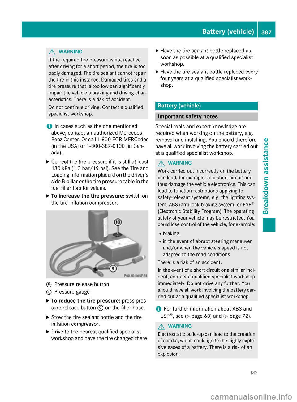
X To increase the tire pressure: switch on
the tire inflation compressor. 006D
Pressure release button
006E Pressure gauge
X To reduce the tire pressure: press pres-
sure release button 006Don the filler hose.
X Stow the tire sealant bottle and the tire
inflation compressor.
X Drive to the nearest qualified specialist
workshop and have the tire changed there. X
Have the tire sealant bottle replaced as
soon as possible at a qualified specialist
workshop.
X Have the tire sealant bottle replaced every
four years at a qualified specialist work-
shop. Battery (vehicle)
Important safety notes
Special tools and expert knowledge are
required when working on the battery, e.g.
removal and installing. You should therefore
have all work involving the battery carried out
at a qualified specialist workshop. G
WARNING
Work carried out incorrectly on the battery
can lead, for example, to a short circuit and
thus damage the vehicle electronics. This can lead to function restrictions applying to
safety-relevant systems, e.g. the lighting sys-
tem, ABS (anti-lock braking system) or ESP ®
(Electronic Stability Program). The operating
safety of your vehicle may be restricted. You
could lose control of the vehicle, for example:
R braking
R in the event of abrupt steering maneuver
and/or when the vehicle's speed is not
adapted to the road conditions
There is a risk of an accident.
In the event of a short circuit or a similar inci- dent, contact a qualified specialist workshop
immediately. Do not drive any further. You
should have all work involving the battery car-
ried out at a qualified specialist workshop.
i For further information about ABS and
ESP ®
, see (Y page 68) and (Y page 72). G
WARNING
Electrostatic build-up can lead to the creation of sparks, which could ignite the highly explo-
sive gases of a battery. There is a risk of an
explosion. Battery (vehicle)
387Breakdown assistance
Z
Page 392 of 466

!
Only use battery chargers with a maxi-
mum charging voltage of 14.8 V.
! Only charge the battery using the jump-
starting connection point.
If, at low temperatures, the indicator lamps/
warning lamps in the instrument cluster do
not light up, it is highly likely that the dis-
charged battery has frozen. In this case you
may neither jump-start the vehicle nor charge the battery. The service life of a thawed-out
battery may be shorter. The starting charac-
teristics can be impaired, particularly at low
temperatures. Have the thawed-out battery
checked at a qualified specialist workshop.
Never charge a battery still installed in the
vehicle unless a battery charger unit
approved by Mercedes-Benz is being used. An
accessory battery charge unit specially adap- ted for Mercedes-Benz vehicles and tested
and approved by Mercedes-Benz is available.
It permits the charging of the battery in its
installed position. Contact an authorized
Mercedes-Benz Center for further informa-
tion and availability. Charge the battery in
accordance with the separate instructions for the battery charger.
The jump-starting connection point is in the
engine compartment (Y page 391).
Read the battery charger's operating instruc- tions before charging the battery.
X Open the hood.
X Connect the battery charger to the positive
terminal and ground point in the same
order as when connecting the donor bat-
tery in the jump-starting procedure
(Y page 391). 390
Battery (vehicle)Breakdown assistance
Page 394 of 466

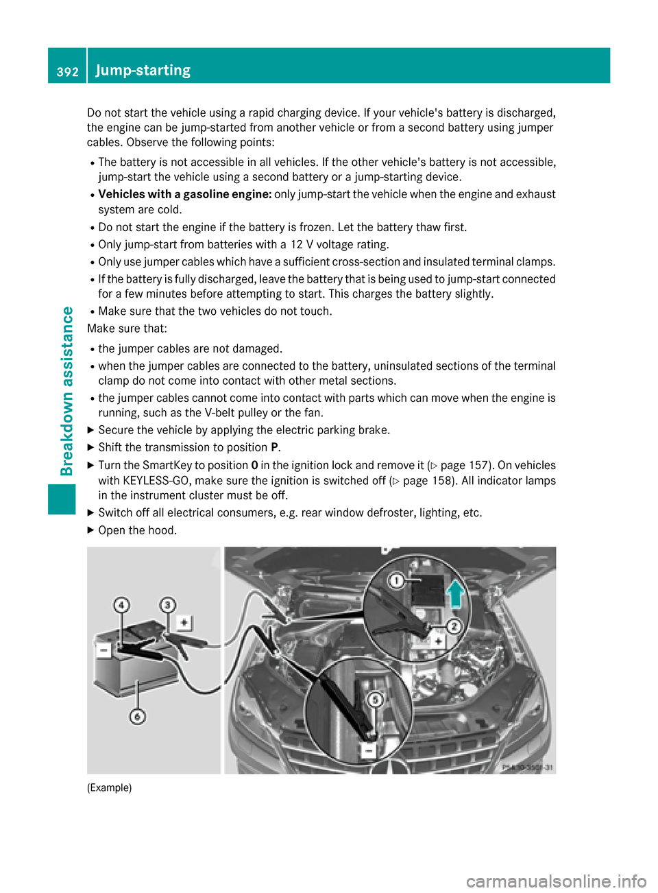
Do not start the vehicle using a rapid charging device. If your vehicle's battery is discharged,
the engine can be jump-started from another vehicle or from a second battery using jumper
cables. Observe the following points:
R The battery is not accessible in all vehicles. If the other vehicle's battery is not accessible,
jump-start the vehicle using a second battery or a jump-starting device.
R Vehicles with a gasoline engine: only jump-start the vehicle when the engine and exhaust
system are cold.
R Do not start the engine if the battery is frozen. Let the battery thaw first.
R Only jump-start from batteries with a 12 V voltage rating.
R Only use jumper cables which have a sufficient cross-section and insulated terminal clamps.
R If the battery is fully discharged, leave the battery that is being used to jump-start connected
for a few minutes before attempting to start. This charges the battery slightly.
R Make sure that the two vehicles do not touch.
Make sure that:
R the jumper cables are not damaged.
R when the jumper cables are connected to the battery, uninsulated sections of the terminal
clamp do not come into contact with other metal sections.
R the jumper cables cannot come into contact with parts which can move when the engine is
running, such as the V-belt pulley or the fan.
X Secure the vehicle by applying the electric parking brake.
X Shift the transmission to position P.
X Turn the SmartKey to position 0in the ignition lock and remove it (Y page 157). On vehicles
with KEYLESS-GO, make sure the ignition is switched off (Y page 158). All indicator lamps
in the instrument cluster must be off.
X Switch off all electrical consumers, e.g. rear window defroster, lighting, etc.
X Open the hood. (Example)392
Jump-startingBreakdown assistance
Page 396 of 466

!
Only secure the tow rope or tow bar at the
towing eyes. Otherwise, the vehicle could
be damaged.
! Do not use the trailer tow hitch for recov-
ery or towing. Do not use the towing eye for
recovery. this could damage the vehicle. If
in doubt, have the vehicle recovered using
a crane.
! When towing, pull away slowly and
smoothly. Pull the towed vehicle as straight
as possible and not at an acute angle.
Excessive tractive power could damage the
vehicles.
i When towing, it is preferable to use a rigid
towing bar as opposed to a tow rope. A rigid
towing bar helps to keep the tractive power low.
! When towing vehicles with KEYLESS-GO,
use the key instead of the Start/Stop but-
ton. Otherwise, the automatic transmission
may shift to position Pwhen the driver's or
front-passenger door are opened, which
could lead to damage to the transmission.
! Do not tow with sling-type equipment.
This could damage the vehicle.
! Vehicles with differential locks: make
sure the differential locks are in automatic
mode. When towing, the differential locks
must not be switched on. The transmission
may otherwise be damaged.
! The vehicle can be towed a maximum of
30 miles (50km). The towing speed of
30 mph (50 km/h) must not be exceeded.
If the vehicle has to be towed more than
30 miles (50km), the entire vehicle must be
raised and transported.
! If you tow or tow-start another vehicle, its
weight must not exceed the maximum per- missible gross vehicle weight of your vehi-
cle.
i Information on your vehicle's gross vehi-
cle weight rating can be found on the vehi-
cle identification plate (Y page 446).It is better to have the vehicle transported
than to have it towed.
If the vehicle has suffered transmission dam-
age, have it transported on a transporter or
trailer.
The automatic transmission must be in posi-
tion Nwhen the vehicle is being towed.
The battery must be connected and charged.
Otherwise, you:
R cannot turn the SmartKey to position 2in
the ignition lock
R cannot release the electric parking brake
R cannot shift the automatic transmission to
position N
i Disarm the automatic locking feature
before the vehicle is towed (Y page 279).
You could otherwise be locked out when
pushing or towing the vehicle. Installing/removing the towing eye
Installing the towing eye Example: towing eye mounting covers
0043 Front cover
0044 Back cover
The brackets for the screw-in towing eyes are
located in the bumpers. They are at the front and at the rear, behind the covers. 394
Towing and tow-startingBreakdown assistance
Page 397 of 466

X
Remove the towing eye from the vehicle
tool kit (Y page 382).
X To open the cover at the front: press the
mark on cover 0043inwards in the direction
of the arrow.
X To open the cover at the rear: insert a
flat, blunt object into the cutout and lever
cover 0044out of the bumper.
X Take cover 0043or0044 off the opening.
X Screw in and tighten the towing eye clock-
wise to the stop.
Removing the towing eye X
Unscrew and remove the towing eye.
X Attach cover 0043or0044 to the bumper and
press until it engages.
X Place the towing eye in the vehicle tool kit. Towing the vehicle with the rear axle
raised
! The ignition must be switched off if you
are towing the vehicle with the rear axle
raised. Intervention by ESP ®
could other-
wise damage the brake system.
Only possible for vehicles without
4MATIC.
X Switch on the hazard warning lamps
(Y page 124).
X Bring the front wheels into the straight-
ahead position.
X Turn the SmartKey to position 0in the igni-
tion lock and remove the SmartKey from
the ignition lock.
X When leaving the vehicle, take the Smart-
Key or the KEYLESS-GO key with you.
When towing your vehicle with the rear axle
raised, it is important that you observe the
safety instructions (Y page 393). Towing a vehicle with both axles on
the ground
It is important that you observe the safety
instructions when towing away your vehicle
(Y page 393).
The automatic transmission automatically
shifts to position Pwhen you open the driver's
or front-passenger door or when you remove the SmartKey from the ignition lock.
In order to ensure that the automatic trans-
mission stays in position Nwhen towing the
vehicle, you must observe the following
points:
X Make sure that the vehicle is stationary and
the SmartKey in the ignition lock is in posi-
tion 0.
X Turn the SmartKey to position 2in the igni-
tion lock.
On vehicles with KEYLESS-GO, use the
SmartKey instead of the Start/Stop button
(Y page 158).
X Depress and hold the brake pedal.
X Shift the automatic transmission to posi-
tion N.
X Release the brake pedal.
X Release the electric parking brake.
X Leave the SmartKey in position 2in the
ignition lock.
X Switch on the hazard warning lamps
(Y page 124).
i In order to signal a change of direction
when towing the vehicle with the hazard
warning lamps switched on, use the com-
bination switch as usual. In this case, only
the indicator lamps for the direction of
travel flash. After resetting the combina-
tion switch, the hazard warning lamp starts
flashing again. Transporting the vehicle
! You may only secure the vehicle by the
wheels, not by parts of the vehicle such as Towing and tow-starting
395Breakdown assistance Z