2015 MERCEDES-BENZ M-Class Page 53
[x] Cancel search: Page 53Page 341 of 466
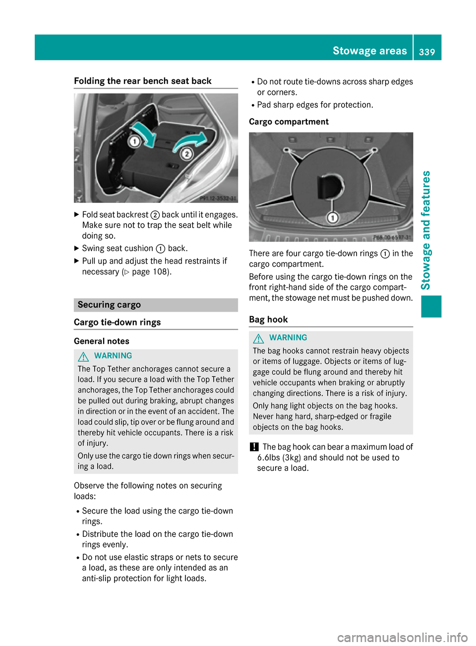
Folding the rear bench seat back
X
Fold seat backrest 0044back until it engages.
Make sure not to trap the seat belt while
doing so.
X Swing seat cushion 0043back.
X Pull up and adjust the head restraints if
necessary (Y page 108). Securing cargo
Cargo tie-down rings General notes
G
WARNING
The Top Tether anchorages cannot secure a
load. If you secure a load with the Top Tether
anchorages, the Top Tether anchorages could be pulled out during braking, abrupt changes
in direction or in the event of an accident. The load could slip, tip over or be flung around and
thereby hit vehicle occupants. There is a risk
of injury.
Only use the cargo tie down rings when secur-
ing a load.
Observe the following notes on securing
loads:
R Secure the load using the cargo tie-down
rings.
R Distribute the load on the cargo tie-down
rings evenly.
R Do not use elastic straps or nets to secure
a load, as these are only intended as an
anti-slip protection for light loads. R
Do not route tie-downs across sharp edges
or corners.
R Pad sharp edges for protection.
Cargo compartment There are four cargo tie-down rings
0043in the
cargo compartment.
Before using the cargo tie-down rings on the
front right-hand side of the cargo compart-
ment, the stowage net must be pushed down.
Bag hook G
WARNING
The bag hooks cannot restrain heavy objects
or items of luggage. Objects or items of lug-
gage could be flung around and thereby hit
vehicle occupants when braking or abruptly
changing directions. There is a risk of injury.
Only hang light objects on the bag hooks.
Never hang hard, sharp-edged or fragile
objects on the bag hooks.
! The bag hook can bear a maximum load of
6.6lbs (3kg)and should not be used to
secure a load. Stowage areas
339Stowage and features Z
Page 344 of 466
cover and net will otherwise not be locked
in place. Cargo net in combined cargo cover
and net
Important safety notes G
WARNING
On its own, the cargo net cannot secure or
restrain heavy objects, items of luggage and
heavy loads. You could be hit by an unsecured load during sudden changes in direction,
braking or in the event of an accident. There isan increased risk of injury or even fatal injury.
Always store objects so that they cannot be
flung around. Secure objects, luggage or
loads against slipping or tipping over, e.g. by
using tie downs, even if you are using the
cargo net.
It is important to use a cargo net if you load
the vehicle with small objects above the seat backrests. For safety reasons, always use a
cargo net when transporting loads.
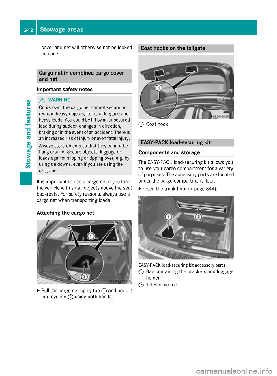
Attaching the cargo net X
Pull the cargo net up by tab 0043and hook it
into eyelets 0044using both hands. Coat hooks on the tailgate
0043
Coat hook EASY-PACK load-securing kit
Components and storage The EASY-PACK load-securing kit allows you
to use your cargo compartment for a variety
of purposes. The accessory parts are located
under the cargo compartment floor.
X Open the trunk floor (Y page 344). EASY-PACK load-securing kit accessory parts
0043 Bag containing the brackets and luggage
holder
0044 Telescopic rod 342
Stowage areasStowage and features
Page 345 of 466
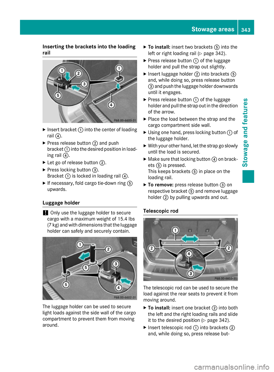
Inserting the brackets into the loading
rail X
Insert bracket 0043into the center of loading
rail 0085.
X Press release button 0044and push
bracket 0043into the desired position in load-
ing rail 0085.
X Let go of release button 0044.
X Press locking button 0087.
Bracket 0043is locked in loading rail 0085.
X If necessary, fold cargo tie-down ring 0083
upwards.
Luggage holder !
Only use the luggage holder to secure
cargo with a maximum weight of 15.4 lbs
(7 kg) and with dimensions that the luggage holder can safely and securely contain. The luggage holder can be used to secure
light loads against the side wall of the cargo
compartment to prevent them from moving
around. X
To install: insert two brackets 0083into the
left or right loading rail (Y page 342).
X Press release button 0043of the luggage
holder and pull the strap out slightly.
X Insert luggage holder 0044into brackets 0083
and, while doing so, press release button
0087 and push the luggage holder downwards
until it engages.
X Press release button 0043of the luggage
holder and pull the strap out in the direction
of the arrow.
X Place the load between the strap and the
cargo compartment side wall.
X Using one hand, press locking button 0043of
the luggage holder.
X With your other hand, let the strap go slowly
until the load is secured.
X Make sure that locking button 0085on brack-
ets 0083is pressed.
This keeps brackets 0083in place on the
loading rail.
X To remove: press release button 0087on
respective bracket 0083and remove luggage
holder 0044by pulling upwards and out.
Telescopic rod The telescopic rod can be used to secure the
load against the rear seats to prevent it from
moving around.
X To install: insert one bracket 0044into both
the left and the right loading rails and slide it to the desired position (Y page 342).
X Insert telescopic rod 0043into brackets 0044
and, while doing so, press release but- Stowage areas
343Stowage and featu res Z
Page 347 of 466
Roof carrier
Important safety notes G
WARNING
When you load the roof, the center of gravity
of the vehicle rises and the driving character- istics change. If you exceed the maximum roof
load, the driving characteristics, as well as
steering and braking, will be greatly impaired. There is a risk of an accident.
Never exceed the maximum roof load and
adjust your driving style.
! Mercedes-Benz recommends that you
only use roof carriers that have been tested
and approved for Mercedes-Benz vehicles.
This helps to prevent damage to the vehi-
cle.
Position the load on the roof carrier in such
a way that the vehicle will not sustain dam-
age even when it is in motion.
Depending on the vehicle equipment,
ensure that when the roof carrier is instal-
led you can:
R raise the sliding sunroof fully
R open the panorama roof with power tilt/
sliding panel fully
R open the tailgate fully
The maximum roof load is 220 lbs(100 kg).
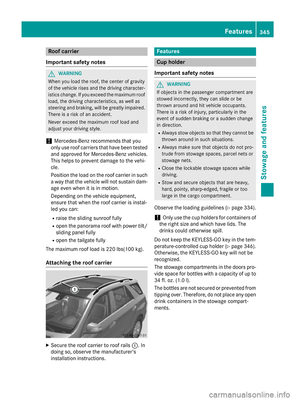
Attaching the roof carrier X
Secure the roof carrier to roof rails 0043. In
doing so, observe the manufacturer's
installation instructions. Features
Cup holder
Important safety notes G
WARNING
If objects in the passenger compartment are
stowed incorrectly, they can slide or be
thrown around and hit vehicle occupants.
There is a risk of injury, particularly in the
event of sudden braking or a sudden change
in direction. R Always stow objects so that they cannot be
thrown around in such situations.
R Always make sure that objects do not pro-
trude from stowage spaces, parcel nets or
stowage nets.
R Close the lockable stowage spaces while
driving.
R Stow and secure objects that are heavy,
hard, pointy, sharp-edged, fragile or too
large in the cargo compartment.
Observe the loading guidelines (Y page 334).
! Only use the cup holders for containers of
the right size and which have lids. The
drinks could otherwise spill.
Do not keep the KEYLESS-GO key in the tem-
perature-controlled cup holder (Y page 346).
Otherwise, the KEYLESS-GO key will not be
recognized.
The stowage compartments in the doors pro- vide space for bottles with a capacity of up to
34 fl. oz. (1.0 l).
The bottles are not secured or prevented from
tipping over. Therefore, do not place any open
drink containers in the stowage compart-
ments. Features
345Stowage and features Z
Page 351 of 466
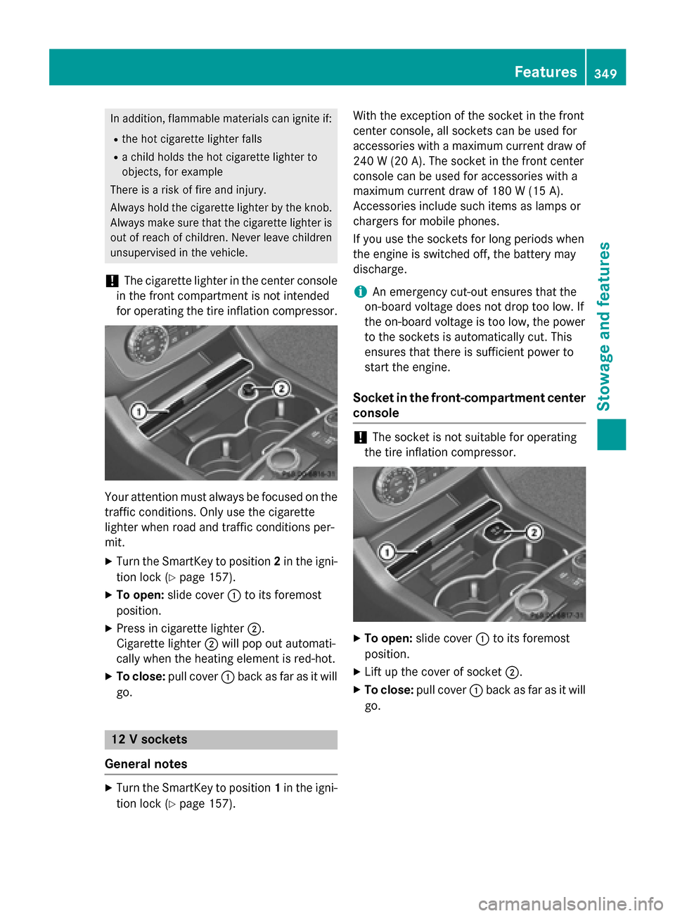
In addition, flammable materials can ignite if:
R the hot cigarette lighter falls
R a child holds the hot cigarette lighter to
objects, for example
There is a risk of fire and injury.
Always hold the cigarette lighter by the knob.
Always make sure that the cigarette lighter is
out of reach of children. Never leave children unsupervised in the vehicle.
! The cigarette lighter in the center console
in the front compartment is not intended
for operating the tire inflation compressor. Your attention must always be focused on the
traffic conditions. Only use the cigarette
lighter when road and traffic conditions per-
mit.
X Turn the SmartKey to position 2in the igni-
tion lock (Y page 157).
X To open: slide cover 0043to its foremost
position.
X Press in cigarette lighter 0044.
Cigarette lighter 0044will pop out automati-
cally when the heating element is red-hot.
X To close: pull cover 0043back as far as it will
go. 12 V sockets
General notes X
Turn the SmartKey to position 1in the igni-
tion lock (Y page 157). With the exception of the socket in the front
center console, all sockets can be used for
accessories with a maximum current draw of 240 W (20 A). The socket in the front center
console can be used for accessories with a
maximum current draw of 180 W (15 A).
Accessories include such items as lamps or
chargers for mobile phones.
If you use the sockets for long periods when
the engine is switched off, the battery may
discharge.
i An emergency cut-out ensures that the
on-board voltage does not drop too low. If
the on-board voltage is too low, the power
to the sockets is automatically cut. This
ensures that there is sufficient power to
start the engine.
Socket in the front-compartment center
console !
The socket is not suitable for operating
the tire inflation compressor. X
To open: slide cover 0043to its foremost
position.
X Lift up the cover of socket 0044.
X To close: pull cover 0043back as far as it will
go. Features
349Stowage and features Z
Page 354 of 466

Problems with the 115 V power socket
Problem
Possible causes/consequences and
0050
0050Solutions The warning lamp on
the 115 V power socket
is not lit. The on-board voltage is too low because the battery is too weak.
X Start the engine.
or
X Charge the battery (Y page 389).
If the indicator lamp still does not light up:
X Visit a qualified specialist workshop. The temperature of the DC/AC converter is temporarily too high.
X Remove the electronic device connector from the 115 V socket.
X Let the DC/AC converter cool down.
If the indicator lamp still does not light up after cooling down the
converter: X Visit a qualified specialist workshop. You have connected an electronic device that has a constant
nominal power of less than 150 watts, but a very high switch-on
current. This device will not work. If you connect such a device, the
115 V power socket will not supply it with power.
X Connect a suitable device. mbrace
General notes You must have a license agreement to acti-
vate the mbrace service. Make sure that your system is activated and operational. To log in,
press the 00D9MB Info call button. If any of
the steps mentioned are not carried out, the
system may not be activated.
If you have questions about the activation,
contact one of the following telephone hot-
lines:
R USA: Mercedes-Benz Customer Assistance
Center at 1-800-FOR-MERCedes
(1-800-367-6372) or 1-866-990-9007
R Canada: Customer Service at
1-888-923-8367 Shortly after successfully registering with the
service, a user ID and password will be sent to you by post.
USA only: you can use this password to log
onto the mbrace area under "Owners Online"
at http://www.mbusa.com.
The system is available if:
R it has been activated and is operational
R the corresponding mobile phone network is
available for transmitting data to the Cus-
tomer Center
R a service subscription is available
R the starter battery is sufficiently charged
i Determining the location of the vehicle on
a map is only possible if:
R GPS reception is available.
R the vehicle position can be forwarded to
the Customer Assistance Center. 352
FeaturesStowage and features
Page 357 of 466

X
Press Roadside Assistance button 0043.
This initiates a call to the Mercedes-Benz
Customer Assistance Center.
The indicator lamp in Roadside Assistance
button 0043flashes while the call is active.
The multifunction display shows the Con‐
Con‐
necting Call
necting Call message. The audio output
is muted.
If a connection can be made, the Call Con‐
Call Con‐
nected nected message appears in the multifunction
display.
If a mobile phone network and GPS reception are available, the system transfers data to the
Mercedes-Benz Customer Assistance Center, for example:
R current location of the vehicle
R vehicle identification number
i The audio system or COMAND display
indicates that a call is active. During the
call, you can change to the navigation menu
by pressing the NAVI button on COMAND,
for example.
Voice output is not available.
A voice connection is established between
the Mercedes-Benz Customer Assistance
Center and the vehicle occupants.
From the vehicle remote malfunction diagno- sis, the Mercedes-Benz Customer Assistance
Center can ascertain the nature of the prob-
lem (Y page 359).
The Mercedes-Benz Customer Assistance
Center either sends a qualified Mercedes-
Benz technician or makes arrangements for
your vehicle to be transported to the nearest
authorized Mercedes-Benz Center.
You may be charged for services such as
repair work and/or towing.
Further details are available in your mbrace
manual. i
The system has not been able to initiate a
Roadside Assistance call, if:
R the indicator lamp for Roadside Assis-
tance call button 0043is flashing continu-
ously.
R no voice connection to the Mercedes-
Benz Customer Assistance Center was
established.
This can occur if the relevant mobile phone network is not available, for example.
The Call Failed
Call Failed message appears in the
multifunction display.
X To end a call: press the0076button on the
multifunction steering wheel.
or
X Press the corresponding button for ending
a phone call on the audio system or on
COMAND.
MB Info call button X
Press MB Info call button 0043.
This initiates a call to the Mercedes-Benz
Customer Assistance Center.
The indicator lamp in MB Info call button 0043
flashes while the connection is being made.
The multifunction display shows the Con‐ Con‐
necting
necting Call
Callmessage. The audio system
is muted.
If a connection can be made, the Call Con‐
Call Con‐
nected
nected message appears in the multifunction
display. Features
355Stowage and features Z
Page 361 of 466

i
If the anti-theft alarm system is activated
for longer than 30 seconds, the Mercedes-
Benz Customer Assistance Center is auto-
matically notified.
Vehicle remote malfunction diagnosis With the vehicle remote malfunction diagno-
sis (Vehicle Health Check), the Customer
Assistance center can provide improved sup- port for problems with your vehicle. During anexisting call, vehicle data is transferred to the
Customer Assistance center. The customer
service representative can use the received
data to decide what kind of assistance is
required. You are then, for example, guided to the nearest authorized Mercedes-Benz Cen-
ter or a recovery vehicle is called.
If vehicle data needs to be transferred during
an MB Info call or a Roadside Assistance call, this is initiated by the Customer Assistance
center. You will see the Roadside Assis‐
Roadside Assis‐
tance Connected tance Connected message in the COMAND
display. If the vehicle remote malfunction
diagnosis can be started, the Request for
Request for
vehicle diagnosis received. Start
vehicle diagnosis received. Start
vehicle diagnosis?
vehicle diagnosis? message appears in
the display.
X Confirm the message with Yes
Yes.
X When the Vehicle Diagnosis Please
Vehicle Diagnosis Please
start ignition
start ignition message appears, turn
the SmartKey to position 2in the ignition
lock (Y page 157).
X When the Please
Please follow
followthe
theinstruc‐
instruc‐
tions received by phone and move
tions received by phone and move
your vehicle to a safe position. your vehicle to a safe position.
message appears, follow the customer ser-
vice representative's instructions.
The message in the display disappears.
If you select Cancel Cancel, the vehicle remote
malfunction diagnosis is canceled com-
pletely.
The vehicle operating state check begins.
You will see the Vehicle diagnosis Vehicle diagnosis
activated.
activated. message. When the diagnosis is completed, the
Send Send
vehicle diagnostics data//(Voice vehicle diagnostics data//(Voice
connection may be//interrupted dur‐ connection may be//interrupted dur‐
ing ing data
data transfer)
transfer) message appears. The
vehicle data can now be sent to the Customer Assistance center.
X Press OK
OKto confirm the message.
The voice connection with the Customer
Assistance center is terminated.
You will see the Vehicle Diagnosis: Vehicle Diagnosis:
Transferring data... Transferring data... message.
The vehicle data is sent to the Customer
Assistance center.
Depending on what the customer service rep-
resentative agreed with you, the voice con-
nection is re-established after the transfer is
complete. If necessary, you will be contacted at a later time by another means, e.g. by e-
mail or phone.
Further functions of the vehicle remote mal-
function diagnosis include, for example:
R transfer of service data to the Customer
Assistance center. If a service is overdue,
the COMAND display shows a message
about various special offers at your work-
shop.
R monthly status information e-mail on oil
level, air pressure, maintenance, brakes,
etc. If applicable, you will receive informa-
tion on special offers in the e-mail.
USA only: this information can also be
called up under "Owners Online" at http://
www.mbusa.com.
Information on the data stored in the vehicle
(Y page 30).
Information on Roadside Assistance
(Y page 26).
Downloading routes Downloading routes allows you to transfer
and save predefined routes in the navigation
system. To do this, an SD memory card must
be inserted into the COMAND system. If no
SD memory card is inserted, you must insert Features
359Stowage and features Z