2015 MERCEDES-BENZ M-Class drive
[x] Cancel search: drivePage 257 of 466

Messages in the multifunction display
If a gear change process has not been successful, the following messages may be displayed in
the multifunction display: Display messages
Possible causes/consequences and
0050 0050Solutions LOW RANGE Max.
LOW RANGE Max.
Speed 40 km/h Speed 40 km/h You have been driving faster than 40 km/h. Additionally, the indi-
cator lamp on the button in the center console blinks.
X Drive more slowly to carry out the gear change process. LOW
LOW
RANGE
RANGE Shift
Shiftto
to
Position N Briefly
Position N Briefly The transmission is in position
Dand you are driving at below
40 km/h.
X Shift the transmission to Nto complete the gear change proc-
ess. LOW
LOW
RANGE
RANGE Shifting
Shifting
Canceled Please
Canceled Please
Reactivate Reactivate The gear change process was not carried out.
X Ensure that all gear change conditions are fulfilled and carry out
the gear change process again. LOW RANGE Stop
LOW RANGE Stop
Apply Apply
Parking
Parking Brake
Brake A warning tone also sounds. The gear change process has not been
completed. LOW RANGE is in the neutral position. There is no
connection between the engine and the drive wheels.
! Do not drive any further. You could otherwise damage the
vehicle's drive train.
X Stop the vehicle. Take into account the road and traffic condi-
tions when doing this.
X Depress the electric parking brake (Y page 184).
X Carry out the gear change process again.
If the gear change process has been carried out, the LOW LOWRANGE
RANGE
Stop Apply Parking Brake
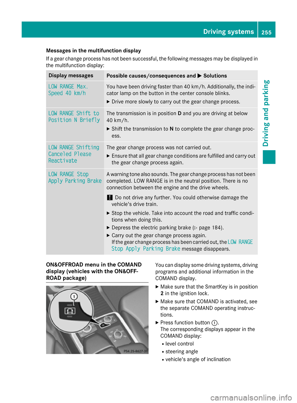
Stop Apply Parking Brake message disappears.ON&OFFROAD menu in the COMAND
display (vehicles with the ON&OFF-
ROAD package) You can display some driving systems, driving
programs and additional information in the
COMAND display.
X Make sure that the SmartKey is in position
2 in the ignition lock.
X Make sure that COMAND is activated, see
the separate COMAND operating instruc-
tions.
X Press function button 0043.
The corresponding displays appear in the
COMAND display:
R level control
R steering angle
R vehicle's angle of inclination Driving systems
255Driving and parking Z
Page 264 of 466

X
Detach the trailer cable and decouple the
trailer.
X Switch off the engine. Permissible trailer loads and drawbar
loads
Weight specifications Maximum permissible gross vehicle
weight rating
The gross trailer weight is calculated by add-
ing the weight of the trailer to the weight of
the load and equipment on the trailer.
You will find installing dimensions and loads
under "Technical data" (Y page 459).
Permissible noseweight
You will find installing dimensions and loads
under "Technical data" (Y page 459).
Loading a trailer R
When loading the trailer, make sure that
neither the permissible gross weight of the
trailer nor the gross vehicle weight is
exceeded. The permissible gross vehicle
weight is indicated on the identification
plate on the B-pillar on the driver's side of
the vehicle.
You can find the maximum permissible val-
ues on the type plates of your vehicle and
the trailer. When calculating how much
weight the vehicle and trailer may carry,
pay attention to the respective lowest val-
ues.
R The trailer drawbar load on the ball coupling
must be added to the rear axle load to avoid exceeding the permissible gross axle
weight. The permissible gross vehicle
weight is indicated on the identification
plate on the B-pillar on the driver's side of
the vehicle.
i Mercedes-Benz recommends a trailer
load where the trailer drawbar noseweight accounts for 8% to 15% of the trailer's per-
missible gross weight.
i The weight of additional accessories, pas-
sengers, and cargo reduces the permissi-
ble trailer load and drawbar load for your
vehicle.
Checking the vehicle and trailer weight R
To check that the weights of the towing
vehicle and the trailer comply with the max-
imum permissible values, have the vehicle/
trailer combination (including the driver,
passengers, and cargo with a fully laden
trailer) weighed on a calibrated weigh-
bridge.
R Check the gross axle weight rating of the
front and rear axles, the gross weight of the
trailer and trailer drawbar load. Removing the ball coupling
X Remove the spring cotter.
X Remove the bolt from the ball coupling
recess.
X Remove the ball coupling from the ball cou-
pling recess.
X Clean the ball coupling if it is dirty.
X Stow the ball coupling so that it cannot be
thrown around.
Observe the loading guidelines (Y page 334)
and the safety notes regarding stowage
spaces (Y page 335).
Information on cleaning and care of the trailer tow hitch can be found at (Y page 376). Storing the ball coupling
G
WARNING
Do not carry the ball coupling in the vehicle
interior if it is not secured.
Otherwise, you and others could be injured by the ball coupling being thrown around if you: 262
Towing a trailerDriving an
d parking
Page 268 of 466

Useful information
i This Operator's Manual describes all
models and all standard and optional equip- ment of your vehicle available at the time of
publication of the Operator's Manual.
Country-specific differences are possible.
Please note that your vehicle may not be
equipped with all features described. This
also applies to safety-related systems and
functions.
i Read the information on qualified special-
ist workshops (Y page 29). Important safety notes
G
WARNING
If you operate information systems and com-
munication equipment integrated in the vehi- cle while driving, you will be distracted from
traffic conditions. You could also lose control of the vehicle. There is a risk of an accident.
Only operate the equipment when the traffic
situation permits. If you are not sure that this
is possible, park the vehicle paying attention
to traffic conditions and operate the equip-
ment when the vehicle is stationary. G
WARNING
If the instrument cluster has failed or mal-
functioned, you may not recognize function
restrictions in systems relevant to safety. The operating safety of your vehicle may be
impaired. There is a risk of an accident.
Drive on carefully. Have the vehicle checked
at a qualified specialist workshop immedi-
ately.
You must observe the legal requirements for
the country in which you are currently driving when operating the on-board computer.
The on-board computer only shows messages
or warnings from certain systems in the mul- tifunction display. You should therefore make
sure your vehicle is operating safely at all times. Otherwise, a vehicle that is not oper-
ating safely may cause an accident.
For an overview, see the instrument panel
illustration (Y
page 35). Displays and operation
Instrument cluster lighting
The lighting in the instrument cluster, in the
displays and the controls in the vehicle inte-
rior can be adjusted using the brightness con-
trol knob.
The brightness control knob is located on the bottom left of the instrument cluster
(Y page 35).
X Turn the brightness control knob clockwise
or counter-clockwise.
If the light switch is set to 0058,0060or
0058, the brightness is dependent upon
the brightness of the ambient light.
i The light sensor in the instrument cluster
automatically controls the brightness of
the multifunction display.
In daylight, the displays in the instrument
cluster are not illuminated. Coolant temperature display
G
WARNING
Opening the hood when the engine is over-
heated or when there is a fire in the engine
compartment could expose you to hot gases
or other service products. There is a risk of
injury.
Let an overheated engine cool down before
opening the hood. If there is a fire in the
engine compartment, keep the hood closed
and contact the fire department.
! A display message is shown if the coolant
temperature is too high.
If the coolant temperature is over 248 ‡
(120 †), do not continue driving. The
engine will otherwise be damaged. 266
Displays and operationOn-board computer and displays
Page 269 of 466

The coolant temperature gauge is in the
instrument cluster on the right-hand side
(Y page 35).
Under normal operating conditions and with
the specified coolant level, the coolant tem-
perature may rise to 248 ‡ (120 †). Tachometer
! Do not drive in the overrevving range, as
this could damage the engine.
The red band in the tachometer indicates the
engine's overrevving range.
The fuel supply is interrupted to protect the
engine when the red band is reached. Outside temperature display
You should pay special attention to road con-
ditions when temperatures are around freez-
ing point.
Bear in mind that the outside temperature
display indicates the temperature measured
and does not record the road temperature.
The outside temperature display is in the mul- tifunction display (Y page 268).
Changes in the outside temperature are dis-
played after a short delay. Speedometer with segments
The segments in the speedometer indicate
which speed range is available.
R Cruise control activated (Y page 195):
The segments light up from the stored
speed to the maximum speed.
R DISTRONIC PLUS activated (Y page 198):
One or two segments in the set speed
range light up.
R DISTRONIC PLUS detects a vehicle in front:
The segments between the speed of the
vehicle in front and the stored speed light
up. Operating the on-board computer
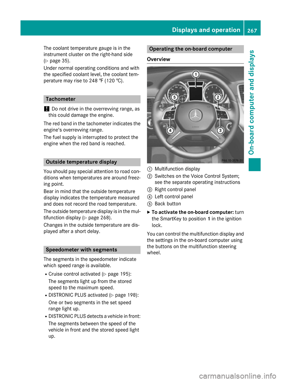
Overview 0043
Multifunction display
0044 Switches on the Voice Control System;
see the separate operating instructions
0087 Right control panel
0085 Left control panel
0083 Back button
X To activate the on-board computer: turn
the SmartKey to position 1in the ignition
lock.
You can control the multifunction display and
the settings in the on-board computer using
the buttons on the multifunction steering
wheel. Displays and operation
267On-board computer and displays Z
Page 271 of 466

0083
Drive program (Y page 168)
0084 Transmission position (Y page 168)
X To show menu bar 0085:press the 0059
or 0065 button on the steering wheel.
Menu bar 0085disappears after a few seconds.
Text field 0087shows the selected menu or
submenu as well as display messages.
i You can set the time using the audio sys-
tem or COMAND; see the separate operat-
ing instructions.
The following messages may appear in the
multifunction display:
0097 Gearshift recommendation, when
shifting manually (Y page 173)
0095005D0096 Active Parking Assist
(Ypage 220)
CRUISE
CRUISE Cruise control (Y
page 195)
LOW
LOW
RANGE RANGE LOW RANGE off-road gear
(Y
page 253)
00CE Adaptive Highbeam Assist
(Ypage 126)
00A7 ECO start/stop function
(Ypage 162)
00D9 HOLD function (Y page 210) Menus and submenus
Menu overview
Press the 0059or0065 button on the steer-
ing wheel to call up the menu bar and select a
menu.
Operating the on-board computer
(Y page 267).
Depending on the equipment installed in the
vehicle, you can call up the following menus:
R Trip Trip menu (Y page 269)
R Navi
Navi menu (navigation instructions)
(Y page 271)
R Audio
Audio menu (Y page 272)
R Tel
Tel menu (telephone) (Y page 273)R
DriveAssist
DriveAssist menu (assistance)
(Y page 275)
R Serv
Serv menu (Y page 276)
R Sett
Sett menu (settings) (Y page 277)
R ON&OFFROAD
ON&OFFROAD menu (Ypage 281)
R AMG
AMG menu in AMG vehicles (Y page 281) Trip menu
Standard display X
Press and hold the 0038button on the
steering wheel until the Trip
Tripmenu with
trip odometer 0043and odometer 0044is
shown.
Trip computer "From Start" or "From
Reset" Example: trip computer "From Start"
0043
Distance
0044 Time
0087 Average speed
0085 Average fuel consumption
X Press the 0059or0065 button on the steer-
ing wheel to select the Trip Tripmenu.
X Press 0063or0064 to select From Start
From Start
or From Reset
From Reset.
The values in the From Start
From Startsubmenu are
calculated from the start of a journey, while
the values in the From Reset
From Resetsubmenu are Menus and submenus
269On-board computer and displays Z
Page 275 of 466

Operating an audio player or audio
media Audio data from various audio devices or
media can be played, depending on the equip- ment installed in the vehicle.
X Switch on COMAND Online and select
audio CD or MP3 mode, see the separate
operating instructions.
X Press the 0059or0065 button on the steer-
ing wheel to select the Audio
Audio menu.
X To select the next/previous track:
briefly press the 0063or0064 button.
X To select a track from the track list
(rapid scrolling): press and hold the 0063
or 0064 button until the desired track has
been reached 0043.
If you press and hold 0063or0064, the
rapid scrolling speed is increased. Not all
audio drives or data carriers support this
function.
If track information is stored on the audio
device or medium, the multifunction display
will show the number and title of the track.
The current track does not appear in audio
AUX mode (Aux iliary audio mode: external
audio source connected).
Video DVD operation Example: CD/DVD changer display X
Switch on COMAND and select video DVD;
see the separate operating instructions.
X Press the 0059or0065 button on the steer-
ing wheel to select the Audio
Audio menu.
X To select the next/previous scene:
briefly press the 0063or0064 button.
X To select a scene from the scene list
(rapid scrolling): press and hold the 0063
or 0064 button until desired scene 0043has
been reached. Telephone menu
Introduction G
WARNING
If you operate information systems and com-
munication equipment integrated in the vehi- cle while driving, you will be distracted from
traffic conditions. You could also lose control of the vehicle. There is a risk of an accident.
Only operate the equipment when the traffic
situation permits. If you are not sure that this
is possible, park the vehicle paying attention
to traffic conditions and operate the equip-
ment when the vehicle is stationary.
When telephoning, you must observe the
legal requirements for the country in which
you are currently driving.
X Switch on the mobile phone (see the sep-
arate operating instructions).
X Switch on COMAND (see the separate
operating instructions).
X Establish a Bluetooth ®
connection to
COMAND; see the separate operating
instructions.
X Press the 0059or0065 button on the steer-
ing wheel to select the Tel Telmenu. Menus and submenus
273On-board computer and displays Z
Page 277 of 466

Assistance menu
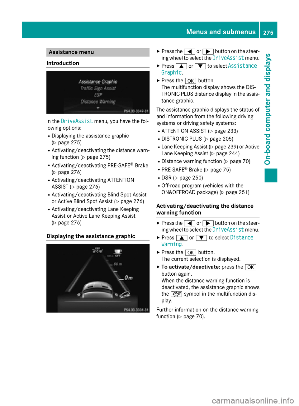
Introduction In the
DriveAssist
DriveAssist menu, you have the fol-
lowing options:
R Displaying the assistance graphic
(Y page 275)
R Activating/deactivating the distance warn-
ing function (Y page 275)
R Activating/deactivating PRE-SAFE ®
Brake
(Y page 276)
R Activating/deactivating ATTENTION
ASSIST (Y page 276)
R Activating/deactivating Blind Spot Assist
or Active Blind Spot Assist (Y page 276)
R Activating/deactivating Lane Keeping
Assist or Active Lane Keeping Assist
(Y page 276)
Displaying the assistance graphic X
Press the 0059or0065 button on the steer-
ing wheel to select the DriveAssist DriveAssistmenu.
X Press 0063or0064 to select Assistance Assistance
Graphic
Graphic.
X Press the 0076button.
The multifunction display shows the DIS-
TRONIC PLUS distance display in the assis- tance graphic.
The assistance graphic displays the status of and information from the following driving
systems or driving safety systems:
R ATTENTION ASSIST (Y page 233)
R DISTRONIC PLUS (Y page 205)
R Lane Keeping Assist (Y page 239) or Active
Lane Keeping Assist (Y page 244)
R Distance warning function (Y page 70)
R PRE-SAFE ®
Brake (Y page 75)
R DSR (Y page 250)
R Off-road program (vehicles with the
ON&OFFROAD package) (Y page 251)
Activating/deactivating the distance
warning function X
Press the 0059or0065 button on the steer-
ing wheel to select the DriveAssist DriveAssistmenu.
X Press 0063or0064 to select Distance
Distance
Warning
Warning.
X Press the 0076button.
The current selection is displayed.
X To activate/deactivate: press the0076
button again.
When the distance warning function is
deactivated, the assistance graphic shows
the 00D4 symbol in the multifunction dis-
play.
Further information on the distance warning
function (Y page 70). Menus and sub
menus
275On-board computer and displays Z
Page 278 of 466

Activating/deactivating PRE-SAFE
®
Brake PRE
‑SAFE ®
Brake is only available in vehicles
with DISTRONIC PLUS.
X Press 0059or0065 on the steering wheel
to select the DriveAssist
DriveAssist menu.
X Press the 0063or0064 button to select
PRE-SAFE Brake
PRE-SAFE Brake.
X Press the 0076button.
The current selection is displayed.
X To activate/deactivate: press the0076
button again.
When PRE-SAFE ®
Brake is deactivated, the
assistance graphic shows the 00D4symbol
in the multifunction display.
For more information on PRE‑SAFE ®
Brake,
see (Y page 75).
Activating/deactivating ATTENTION
ASSIST X
Press the 0059or0065 button on the steer-
ing wheel to select the DriveAssist DriveAssistmenu.
X Press the 0063or0064 button to select
ATTENTION ASSIST
ATTENTION ASSIST .
X Press the 0076button.
The current selection is displayed.
X To activate/deactivate: press the0076
button again.
When ATTENTION ASSIST is deactivated,
the 00D7 symbol appears in the multifunc-
tion display in the assistance graphics dis-
play.
For further information about ATTENTION
ASSIST, see (Y page 233).
Activating/deactivating Blind Spot
Assist X
Press 0059or0065 on the steering wheel
to select the DriveAssist
DriveAssist menu.
X Press the 0063or0064 button to select
Blind Spot Assist
Blind Spot Assist . X
Press the 0076button.
The current selection is displayed.
X To activate/deactivate: press the0076
button again.
For further information about Active Blind
Spot Assist, see (Y page 241).
Activating/deactivating Lane Keeping
Assist X
Press 0059or0065 on the steering wheel
to select the DriveAssist DriveAssist menu.
X Press 0063or0064 to select Lane Keep‐
Lane Keep‐
ing Assist
ing Assist .
X Press the 0076button.
The current selection is displayed.
X Press 0076to confirm.
X Press the 0064or0063 button to set Off
Off,
Standard
Standard orAdaptive
Adaptive.
When Lane Keeping Assist or Active Lane
Keeping Assist is activated, the multifunc-
tion display shows the lane markings as
bright lines in the assistance graphic.
X Press the 0076button to save the setting.
For further information about Lane Keeping
Assist, see (Y page 239).
For further information about Active Lane
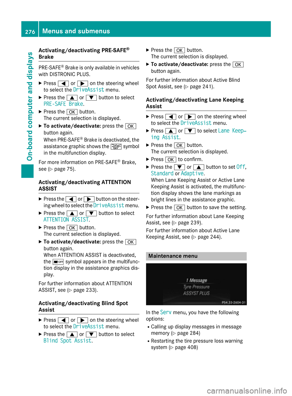
Keeping Assist, see (Y page 244). Maintenance menu
In the
Serv Servmenu, you have the following
options:
R Calling up display messages in message
memory (Y page 284)
R Restarting the tire pressure loss warning
system (Y page 408) 276
Menus and sub
menusOn-board computer and displays