2015 MERCEDES-BENZ M-Class ECU
[x] Cancel search: ECUPage 342 of 466
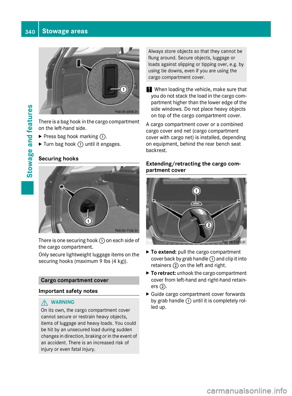
There is a bag hook in the cargo compartment
on the left-hand side.
X Press bag hook marking 0043.
X Turn bag hook 0043until it engages.
Securing hooks There is one securing hook
0043on each side of
the cargo compartment.
Only secure lightweight luggage items on the securing hooks (maximum 9 lbs (4 kg)). Cargo compartment cover
Important safety notes G
WARNING
On its own, the cargo compartment cover
cannot secure or restrain heavy objects,
items of luggage and heavy loads. You could
be hit by an unsecured load during sudden
changes in direction, braking or in the event of an accident. There is an increased risk of
injury or even fatal injury. Always store objects so that they cannot be
flung around. Secure objects, luggage or
loads against slipping or tipping over, e.g. by
using tie downs, even if you are using the
cargo compartment cover.
! When loading the vehicle, make sure that
you do not stack the load in the cargo com- partment higher than the lower edge of the
side windows. Do not place heavy objects
on top of the cargo compartment cover.
A cargo compartment cover or a combined
cargo cover and net (cargo compartment
cover with cargo net) is installed, depending
on equipment, behind the rear bench seat
backrest.
Extending/retracting the cargo com-
partment cover X
To extend: pull the cargo compartment
cover back by grab handle 0043and clip it into
retainers 0044on the left and right.
X To retract: unhook the cargo compartment
cover from left-hand and right-hand retain-
ers 0044.
X Guide cargo compartment cover forwards
by grab handle 0043until it is completely rol-
led up. 340
Stowage areasStowage and features
Page 344 of 466
cover and net will otherwise not be locked
in place. Cargo net in combined cargo cover
and net
Important safety notes G
WARNING
On its own, the cargo net cannot secure or
restrain heavy objects, items of luggage and
heavy loads. You could be hit by an unsecured load during sudden changes in direction,
braking or in the event of an accident. There isan increased risk of injury or even fatal injury.
Always store objects so that they cannot be
flung around. Secure objects, luggage or
loads against slipping or tipping over, e.g. by
using tie downs, even if you are using the
cargo net.
It is important to use a cargo net if you load
the vehicle with small objects above the seat backrests. For safety reasons, always use a
cargo net when transporting loads.
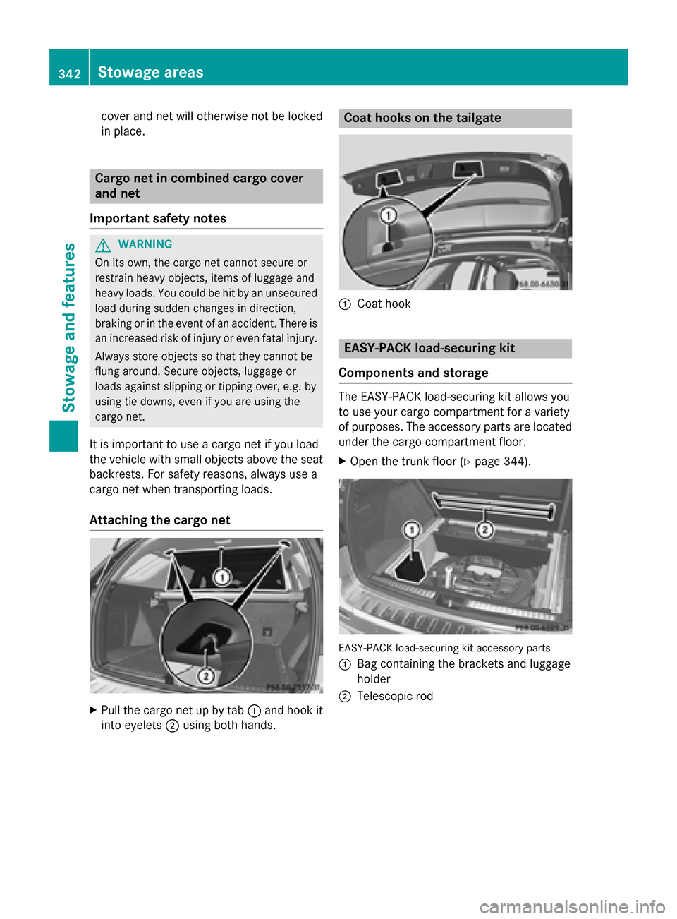
Attaching the cargo net X
Pull the cargo net up by tab 0043and hook it
into eyelets 0044using both hands. Coat hooks on the tailgate
0043
Coat hook EASY-PACK load-securing kit
Components and storage The EASY-PACK load-securing kit allows you
to use your cargo compartment for a variety
of purposes. The accessory parts are located
under the cargo compartment floor.
X Open the trunk floor (Y page 344). EASY-PACK load-securing kit accessory parts
0043 Bag containing the brackets and luggage
holder
0044 Telescopic rod 342
Stowage areasStowage and features
Page 345 of 466
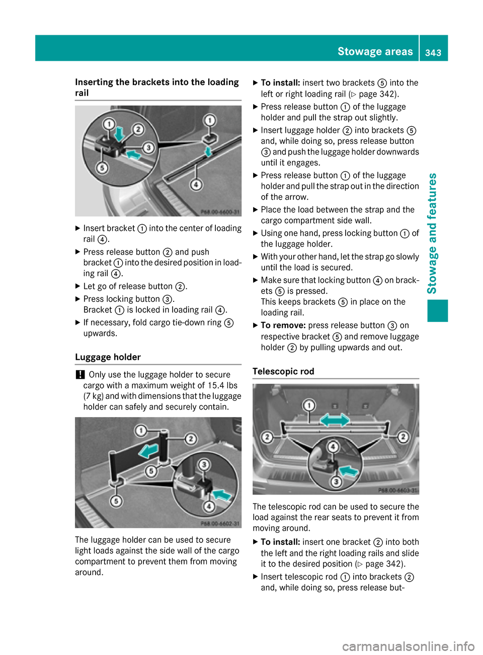
Inserting the brackets into the loading
rail X
Insert bracket 0043into the center of loading
rail 0085.
X Press release button 0044and push
bracket 0043into the desired position in load-
ing rail 0085.
X Let go of release button 0044.
X Press locking button 0087.
Bracket 0043is locked in loading rail 0085.
X If necessary, fold cargo tie-down ring 0083
upwards.
Luggage holder !
Only use the luggage holder to secure
cargo with a maximum weight of 15.4 lbs
(7 kg) and with dimensions that the luggage holder can safely and securely contain. The luggage holder can be used to secure
light loads against the side wall of the cargo
compartment to prevent them from moving
around. X
To install: insert two brackets 0083into the
left or right loading rail (Y page 342).
X Press release button 0043of the luggage
holder and pull the strap out slightly.
X Insert luggage holder 0044into brackets 0083
and, while doing so, press release button
0087 and push the luggage holder downwards
until it engages.
X Press release button 0043of the luggage
holder and pull the strap out in the direction
of the arrow.
X Place the load between the strap and the
cargo compartment side wall.
X Using one hand, press locking button 0043of
the luggage holder.
X With your other hand, let the strap go slowly
until the load is secured.
X Make sure that locking button 0085on brack-
ets 0083is pressed.
This keeps brackets 0083in place on the
loading rail.
X To remove: press release button 0087on
respective bracket 0083and remove luggage
holder 0044by pulling upwards and out.
Telescopic rod The telescopic rod can be used to secure the
load against the rear seats to prevent it from
moving around.
X To install: insert one bracket 0044into both
the left and the right loading rails and slide it to the desired position (Y page 342).
X Insert telescopic rod 0043into brackets 0044
and, while doing so, press release but- Stowage areas
343Stowage and featu res Z
Page 346 of 466
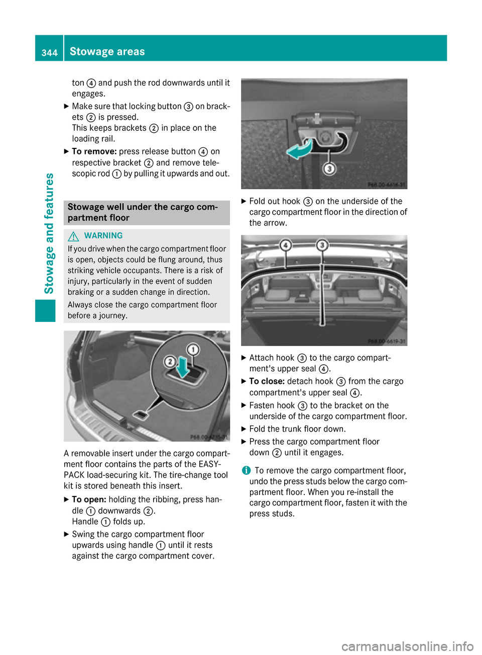
ton
0085and push the rod downwards until it
engages.
X Make sure that locking button 0087on brack-
ets 0044is pressed.
This keeps brackets 0044in place on the
loading rail.
X To remove: press release button 0085on
respective bracket 0044and remove tele-
scopic rod 0043by pulling it upwards and out. Stowage well under the cargo com-
partment floor G
WARNING
If you drive when the cargo compartment floor is open, objects could be flung around, thus
striking vehicle occupants. There is a risk of
injury, particularly in the event of sudden
braking or a sudden change in direction.
Always close the cargo compartment floor
before a journey. A removable insert under the cargo compart-
ment floor contains the parts of the EASY-
PACK load-securing kit. The tire-change tool
kit is stored beneath this insert.
X To open: holding the ribbing, press han-
dle 0043downwards 0044.
Handle 0043folds up.
X Swing the cargo compartment floor
upwards using handle 0043until it rests
against the cargo compartment cover. X
Fold out hook 0087on the underside of the
cargo compartment floor in the direction of the arrow. X
Attach hook 0087to the cargo compart-
ment's upper seal 0085.
X To close: detach hook 0087from the cargo
compartment's upper seal 0085.
X Fasten hook 0087to the bracket on the
underside of the cargo compartment floor.
X Fold the trunk floor down.
X Press the cargo compartment floor
down 0044until it engages.
i To remove the cargo compartment floor,
undo the press studs below the cargo com- partment floor. When you re-install the
cargo compartment floor, fasten it with the
press studs. 344
Sto
wage areasStowage an d features
Page 347 of 466
Roof carrier
Important safety notes G
WARNING
When you load the roof, the center of gravity
of the vehicle rises and the driving character- istics change. If you exceed the maximum roof
load, the driving characteristics, as well as
steering and braking, will be greatly impaired. There is a risk of an accident.
Never exceed the maximum roof load and
adjust your driving style.
! Mercedes-Benz recommends that you
only use roof carriers that have been tested
and approved for Mercedes-Benz vehicles.
This helps to prevent damage to the vehi-
cle.
Position the load on the roof carrier in such
a way that the vehicle will not sustain dam-
age even when it is in motion.
Depending on the vehicle equipment,
ensure that when the roof carrier is instal-
led you can:
R raise the sliding sunroof fully
R open the panorama roof with power tilt/
sliding panel fully
R open the tailgate fully
The maximum roof load is 220 lbs(100 kg).
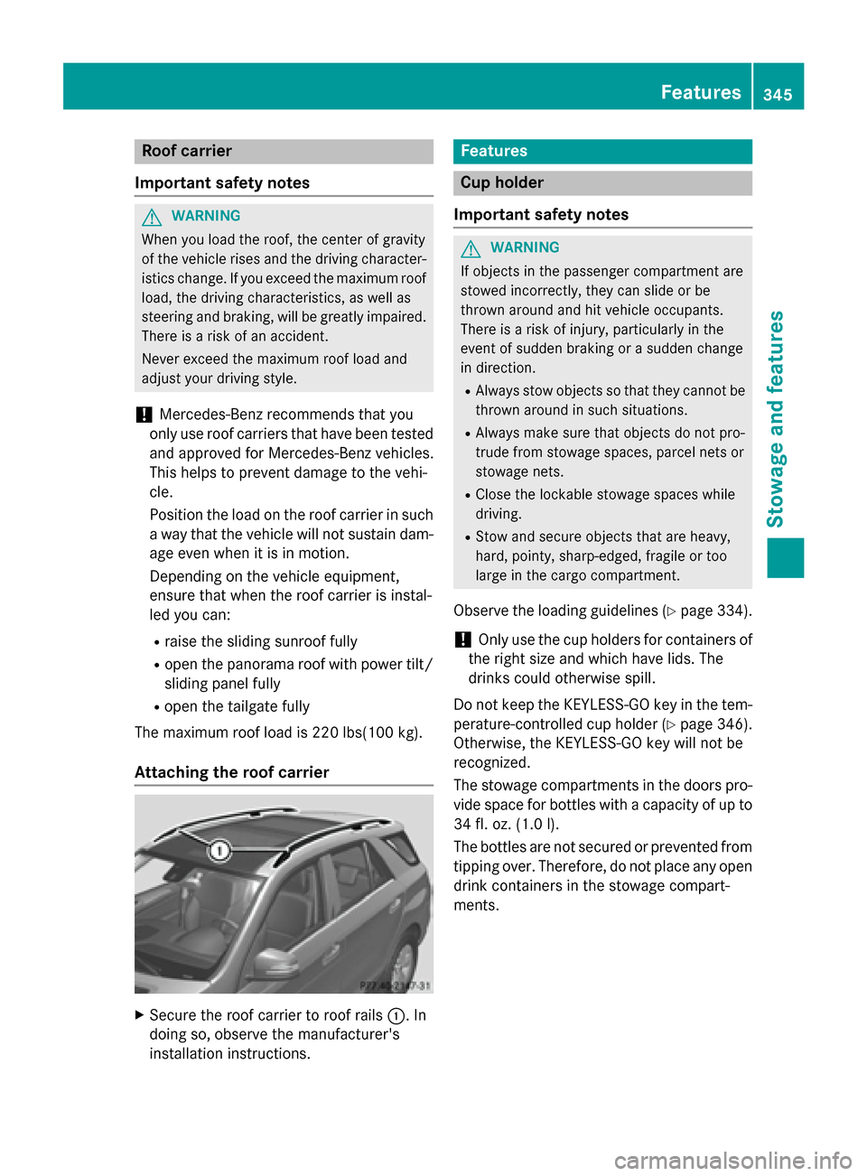
Attaching the roof carrier X
Secure the roof carrier to roof rails 0043. In
doing so, observe the manufacturer's
installation instructions. Features
Cup holder
Important safety notes G
WARNING
If objects in the passenger compartment are
stowed incorrectly, they can slide or be
thrown around and hit vehicle occupants.
There is a risk of injury, particularly in the
event of sudden braking or a sudden change
in direction. R Always stow objects so that they cannot be
thrown around in such situations.
R Always make sure that objects do not pro-
trude from stowage spaces, parcel nets or
stowage nets.
R Close the lockable stowage spaces while
driving.
R Stow and secure objects that are heavy,
hard, pointy, sharp-edged, fragile or too
large in the cargo compartment.
Observe the loading guidelines (Y page 334).
! Only use the cup holders for containers of
the right size and which have lids. The
drinks could otherwise spill.
Do not keep the KEYLESS-GO key in the tem-
perature-controlled cup holder (Y page 346).
Otherwise, the KEYLESS-GO key will not be
recognized.
The stowage compartments in the doors pro- vide space for bottles with a capacity of up to
34 fl. oz. (1.0 l).
The bottles are not secured or prevented from
tipping over. Therefore, do not place any open
drink containers in the stowage compart-
ments. Features
345Stowage and features Z
Page 355 of 466

The mbrace system
To adjust the volume during a call, proceed as
follows:
X Press the 0081or0082 button on the mul-
tifunction steering wheel.
or
X Use the volume controller of the audio sys-
tem/COMAND.
The system offers various services, e.g.:
R Automatic and manual emergency call
R Roadside Assistance call
R MB Info call
USA only: you can find information and a
description of all available features under
"Owners Online" at http://www.mbusa.com.
System self-test After you have switched on the ignition, the
system carries out a self-diagnosis.
A malfunction in the system has been detec-
ted if one of the following occurs:
R The indicator lamp in the SOS button does
not come on during the system self-test.
R The indicator lamp in the 0052Roadside
Assistance button does not light up during
self-diagnosis of the system.
R The indicator lamp in the 00D9MB Info call
button does not light up during self-diag-
nosis of the system.
R The indicator lamp in one or more of the
following buttons continues to light up red
after the system self-diagnosis:
- SOS button
- 0052 Roadside Assistance call button
- 00D9 MB Info call button
R After the system self-diagnosis, the Inop‐
Inop‐
erative
erative orService Not Activated Service Not Activated
message appears in the multifunction dis-
play.
If a malfunction is indicated as outlined
above, the system may not operate as expec-
ted. In the event of an emergency, help will
have to be summoned by other means. Have the system checked at the nearest
authorized Mercedes-Benz Center or contact
the following service hotlines:
R USA: Mercedes-Benz Customer Assistance
Center at 1-800-FOR-MERCedes
(1-800-367-6372) or 1-866-990-9007
R Canada: Customer Service at
1-888-923-8367
Emergency call Important safety notes
G
WARNING
It can be dangerous to remain in the vehicle,
even if you have pressed the SOS button in an emergency if:
R you see smoke inside or outside of the vehi-
cle, e.g. if there is a fire after an accident
R the vehicle is on a dangerous section of
road
R the vehicle is not visible or cannot easily be
seen by other road users, particularly whendark or in poor visibility conditions
There is a risk of an accident and injury.
Leave the vehicle immediately in this or simi-
lar situations as soon as it is safe to do so.
Move to a safe location along with other vehi-
cle occupants. In such situations, secure the
vehicle in accordance with national regula-
tions, e. g. with a warning triangle.
You must have a license agreement to acti-
vate the mbrace service. Make sure that your
system is activated and operational. To reg-
ister, press the 00D9MB Info call button. If
any of the steps mentioned are not carried
out, the system may not be activated.
If you have questions about the activation,
contact one of the following telephone hot-
lines:
R USA: Mercedes-Benz Customer Assistance
Center at 1-800-FOR-MERCedes
(1-800-367-6372) or 1-866-990-9007
R Canada: Customer Service at
1-888-923-8367 Features
353Stowage an d features Z
Page 366 of 466
Floormats
G
WARNING
Objects in the driver's footwell can restrict the pedal travel or obstruct a depressed pedal.
The operating and road safety of the vehicle is
jeopardized. There is a risk of an accident.
Make sure that all objects in the vehicle are
stowed correctly, and that they cannot enter
the driver's footwell. Install the floormats
securely and as specified in order to ensure
sufficient clearance for the pedals. Do not use loose floormats and do not place floormats on
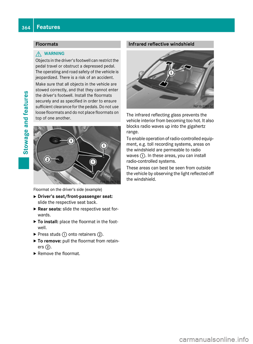
top of one another. Floormat on the driver's side (example)
X Driver's seat/front-passenger seat:
slide the respective seat back.
X Rear seats: slide the respective seat for-
wards.
X To install: place the floormat in the foot-
well.
X Press studs 0043onto retainers 0044.
X To remove: pull the floormat from retain-
ers 0044.
X Remove the floormat. Infrared reflective windshield
The infrared reflecting glass prevents the
vehicle interior from becoming too hot. It also
blocks radio waves up into the gigahertz
range.
To enable operation of radio-controlled equip- ment, e.g. toll recording systems, areas on
the windshield are permeable to radio
waves 0043. In these areas, you can install
radio-controlled systems.
These areas can best be seen from outside
the vehicle by observing the light reflected off
the windshield. 364
FeaturesStowage and featu
res
Page 371 of 466

Example: engine oil cap
X Turn cap 0043counter-clockwise and remove
it.
X Add engine oil.
If the oil level is at or below the MIN mark on
the oil dipstick, add 1.1 US qt (1.0 l)of
engine oil.
X Replace cap 0043on the filler neck and turn
clockwise.
Ensure that the cap locks into place
securely.
X Check the oil level again with the oil dip-
stick (Y page 367).
Further information on engine oil
(Y page 452). Additional service products
Checking coolant level G
WARNING
Certain components in the engine compart-
ment, such as the engine, radiator and parts
of the exhaust system, can become very hot.
Working in the engine compartment poses a
risk of injury.
Where possible, let the engine cool down and touch only the components described in the
following. G
WARNING
The engine cooling system is pressurized, par- ticularly when the engine is warm. When
opening the cap, you could be scalded by hotcoolant spraying out. There is a risk of injury. Let the engine cool down before opening the
cap. Wear eye and hand protection when
opening the cap. Open the cap slowly half a
turn to allow pressure to escape.
X
Park the vehicle on a level surface.
Only check the coolant level when the vehi-
cle is on a level surface and the engine has
cooled down.
X Turn the SmartKey to position 2in the igni-
tion lock (Y page 157).
On vehicles with KEYLESS-GO, press the
Start/Stop button twice (Y page 158).
X Check the coolant temperature gauge in
the multifunction display.
The coolant temperature must be below
158 ‡ (70 †).
X Turn the SmartKey to position
0(Y page 157) in the ignition lock.
X Slowly turn cap 0043half a turn counter-
clockwise to allow excess pressure to
escape.
X Turn cap 0043further counter-clockwise and
remove it.
If the coolant is at the level of marker bar 0087
in the filler neck when cold, there is enough coolant in coolant expansion tank 0044.
If the coolant level is approximately 0.6 in
(1.5 cm) above marker bar 0087in the filler
neck when warm, there is enough coolant
in expansion tank 0044.
X If necessary, add coolant that has been tes-
ted and approved by Mercedes-Benz.
X Replace cap 0043and turn it clockwise as far
as it will go. Engine compartment
369Maintenance and care Z