2015 MERCEDES-BENZ GLK-CLASS SUV width
[x] Cancel search: widthPage 59 of 386
modifications could invalidate the vehicle's
general operating permit.
The use of seat belts and child restraint sys-
tems is required by law in:
R all 50 states
R the U.S. territories
R the District of Columbia
R all Canadian provinces
Even where this is not required by law, all
vehicle occupants should correctly fasten
their seat belts before starting the journey.
iSee "Children in the vehicle" for further
information on infants and children travel-
ing in the vehicle, as well as on child
restraint systems.
Proper use of the seat belts
GWARNING
USE SEAT BELTS PROPERLY
R Seat belts can only work when used prop-
erly. Never wear seat belts in any other way
than as described in this section, as that
could result in serious injuries in the event
of an accident.
R Each occupant should wear their seat belt
at all times, because seat belts help reduce
the likelihood of and potential severity of
injuries in accidents, including rollovers.
The integrated restraint system includes
SRS (driver front air bag, driver's side knee
bag, front-passenger front air bag, side
impact air bags, pelvis air bags, window
curtain air bags for the side windows),
Emergency Tensioning Devices, seat belt
force limiters, and front seat knee bolsters.
The system is designed to enhance the pro-
tection offered to properly belted occu-
pants in certain frontal (front air bags, driv-
er's side knee bag and ETDs) and side (side
impact air bags, window curtain air bags,
and ETDs) impacts which exceed preset
deployment thresholds and in certain roll-
overs (window curtain air bags and ETDs).
R Never wear the shoulder belt under your
arm, across your neck or off your shoulder.
In a frontal crash, your body would move
too far forward. That would increase the
chance of head and neck injuries. The seat belt would also apply too much force to the
ribs or abdomen, which could severely
injure internal organs such as your liver or
spleen.
Adjust the seat belt so that the shoulder
section is located as close as possible to
the middle of the shoulder. It should not
touch the neck. Never pass the shoulder
portion of the seat belt under your arm. For
this purpose, you can adjust the height of
the seat belt outlet.
R Position the lap belt as low as possible on
your hips and not across the abdomen. If
the lap belt is positioned across your abdo-
men, it could cause serious injuries in a
crash.
R Never wear seat belts over rigid or breaka-
ble objects in or on your clothing, such as
eyeglasses, pens, keys etc., as these might cause injuries.
R Make sure the seat belt is always fitted
snugly. Take special care of this when wear-
ing loose clothing.
R Never use a seat belt for more than one
person at a time. Do not fasten a seat belt
around a person and another person or
other objects at the same time.
R Seat belts should not be worn twisted. In a
crash, you would not have the full width of
the seat belt to distribute impact forces.
The twisted seat belt against your body
could cause injuries.
R Pregnant women should also always use a
lap-shoulder belt. The lap belt portion
should be positioned as low as possible on
the hips to avoid any possible pressure on
the abdomen.
R Place the seat backrest in a position that is
as upright as possible.
R Check your seat belt during travel to make
sure it is properly positioned.
Occupant safety57
Safety
Z
Page 185 of 386
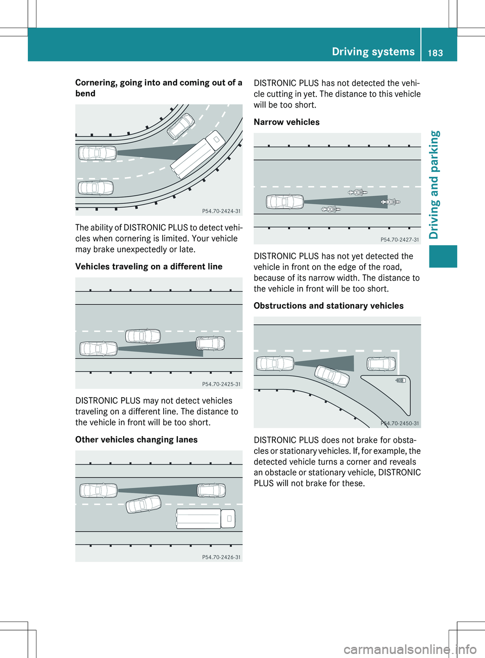
Cornering, going into and coming out of abend
The ability of DISTRONIC PLUS to detect vehi-cles when cornering is limited. Your vehicle
may brake unexpectedly or late.
Vehicles traveling on a different line
DISTRONIC PLUS may not detect vehicles
traveling on a different line. The distance to
the vehicle in front will be too short.
Other vehicles changing lanes
DISTRONIC PLUS has not detected the vehi-
cle cutting in yet. The distance to this vehiclewill be too short.
Narrow vehicles
DISTRONIC PLUS has not yet detected the
vehicle in front on the edge of the road,
because of its narrow width. The distance to
the vehicle in front will be too short.
Obstructions and stationary vehicles
DISTRONIC PLUS does not brake for obsta-
cles or stationary vehicles. If, for example, the
detected vehicle turns a corner and reveals
an obstacle or stationary vehicle, DISTRONIC PLUS will not brake for these.
Driving systems183
Driving and parking
Z
Page 196 of 386
Rif the area is lit by fluorescent bulbs or LED
lighting (the display may flicker)
R if there is a sudden change in temperature,
e.g. when driving into a heated garage in
winter
R if the camera lens is dirty or obstructed
R if the rear of your vehicle is damaged. In this
event, have the camera position and setting checked at a qualified specialist workshop
The field of vision and other functions of the
rear view camera may be restricted due to
additional accessories on the rear of the vehi-
cle (e.g. license plate holder, bicycle rack).
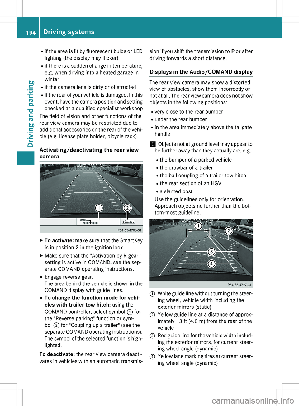
Activating/deactivating the rear view
camera
X To activate: make sure that the SmartKey
is in position 2 in the ignition lock.
X Make sure that the "Activation by R gear"
setting is active in COMAND, see the sep-
arate COMAND operating instructions.
X Engage reverse gear.
The area behind the vehicle is shown in the
COMAND display with guide lines.
X To change the function mode for vehi-
cles with trailer tow hitch: using the
COMAND controller, select symbol : for
the "Reverse parking" function or sym-
bol ; for "Coupling up a trailer" (see the
separate COMAND operating instructions).
The symbol of the selected function is high- lighted.
To deactivate: the rear view camera deacti-
vates in vehicles with an automatic transmis- sion if you shift the transmission to
P or after
driving forwards a short distance.
Displays in the Audio/COMAND display
The rear view camera may show a distorted
view of obstacles, show them incorrectly or
not at all. The rear view camera does not show
objects in the following positions:
R very close to the rear bumper
R under the rear bumper
R in the area immediately above the tailgate
handle
! Objects not at ground level may appear to
be further away than they actually are, e.g.: R the bumper of a parked vehicle
R the drawbar of a trailer
R the ball coupling of a trailer tow hitch
R the rear section of an HGV
R a slanted post
Use the guidelines only for orientation.
Approach objects no further than the bot-
tom-most guideline.
:White guide line without turning the steer-
ing wheel, vehicle width including the
exterior mirrors (static)
;Yellow guide line at a distance of approx-
imately 13 ft (4.0 m) from the rear of the
vehicle
=Red guide line for the vehicle width includ-
ing the exterior mirrors, for current steer-
ing wheel angle (dynamic)
?Yellow lane marking tires at current steer-
ing wheel angle (dynamic)
194Driving systems
Driving and parking
Page 197 of 386
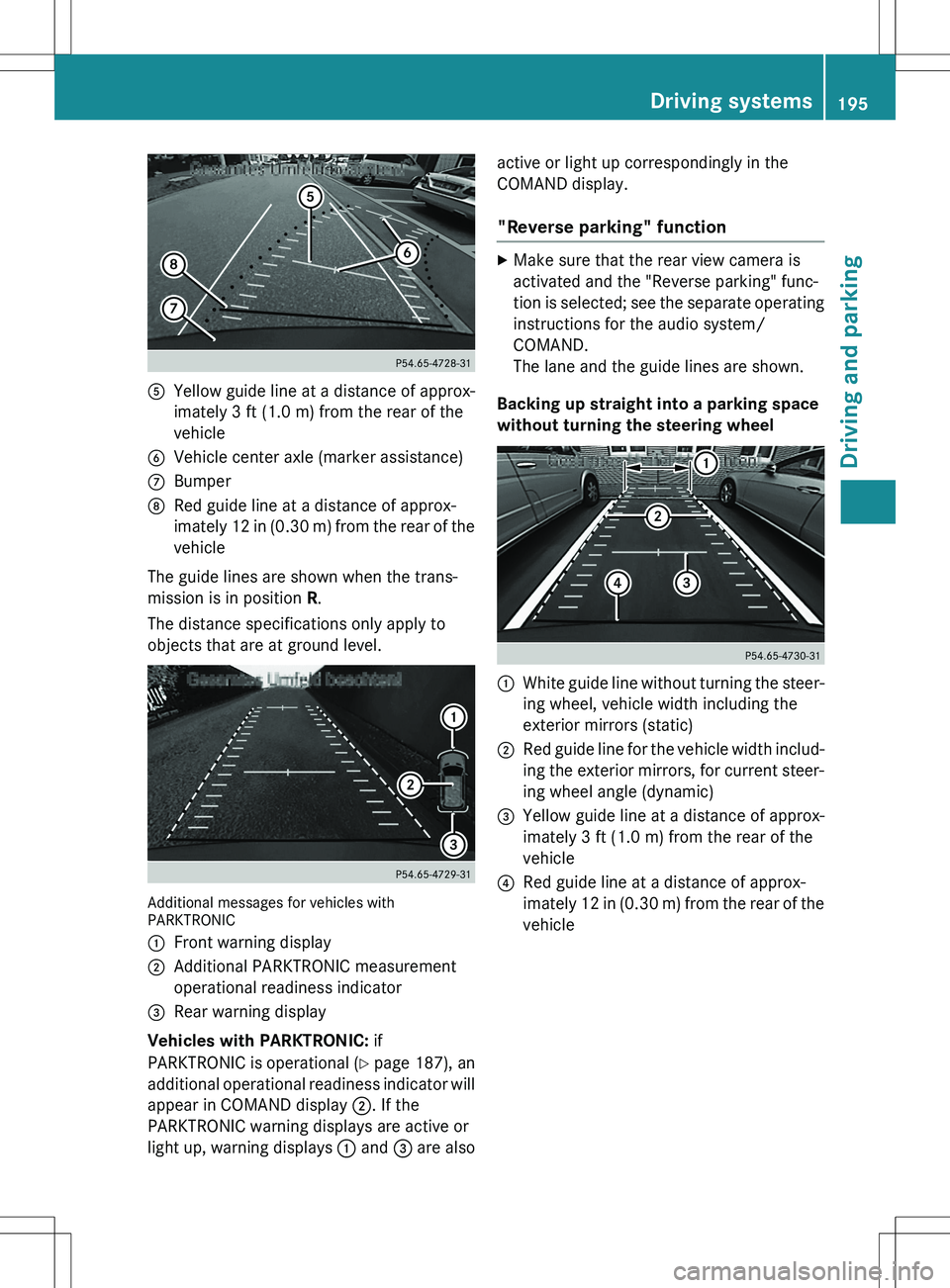
AYellow guide line at a distance of approx-
imately 3 ft (1.0 m) from the rear of the
vehicle
BVehicle center axle (marker assistance)
CBumper
DRed guide line at a distance of approx-
imately 12 in (0.30 m) from the rear of thevehicle
The guide lines are shown when the trans-
mission is in position R.
The distance specifications only apply to
objects that are at ground level.
Additional messages for vehicles with
PARKTRONIC :
Front warning display
;Additional PARKTRONIC measurement
operational readiness indicator
=Rear warning display
Vehicles with PARKTRONIC: if
PARKTRONIC is operational ( Y page 187), an
additional operational readiness indicator will
appear in COMAND display ;. If the
PARKTRONIC warning displays are active or
light up, warning displays : and = are also active or light up correspondingly in the
COMAND display.
"Reverse parking" function
X
Make sure that the rear view camera is
activated and the "Reverse parking" func-
tion is selected; see the separate operating
instructions for the audio system/
COMAND.
The lane and the guide lines are shown.
Backing up straight into a parking space
without turning the steering wheel
:White guide line without turning the steer-
ing wheel, vehicle width including the
exterior mirrors (static)
;Red guide line for the vehicle width includ-
ing the exterior mirrors, for current steer-
ing wheel angle (dynamic)
=Yellow guide line at a distance of approx-
imately 3 ft (1.0 m) from the rear of the
vehicle
?Red guide line at a distance of approx-
imately 12 in (0.30 m) from the rear of the
vehicle
Driving systems195
Driving and parking
Z
Page 198 of 386
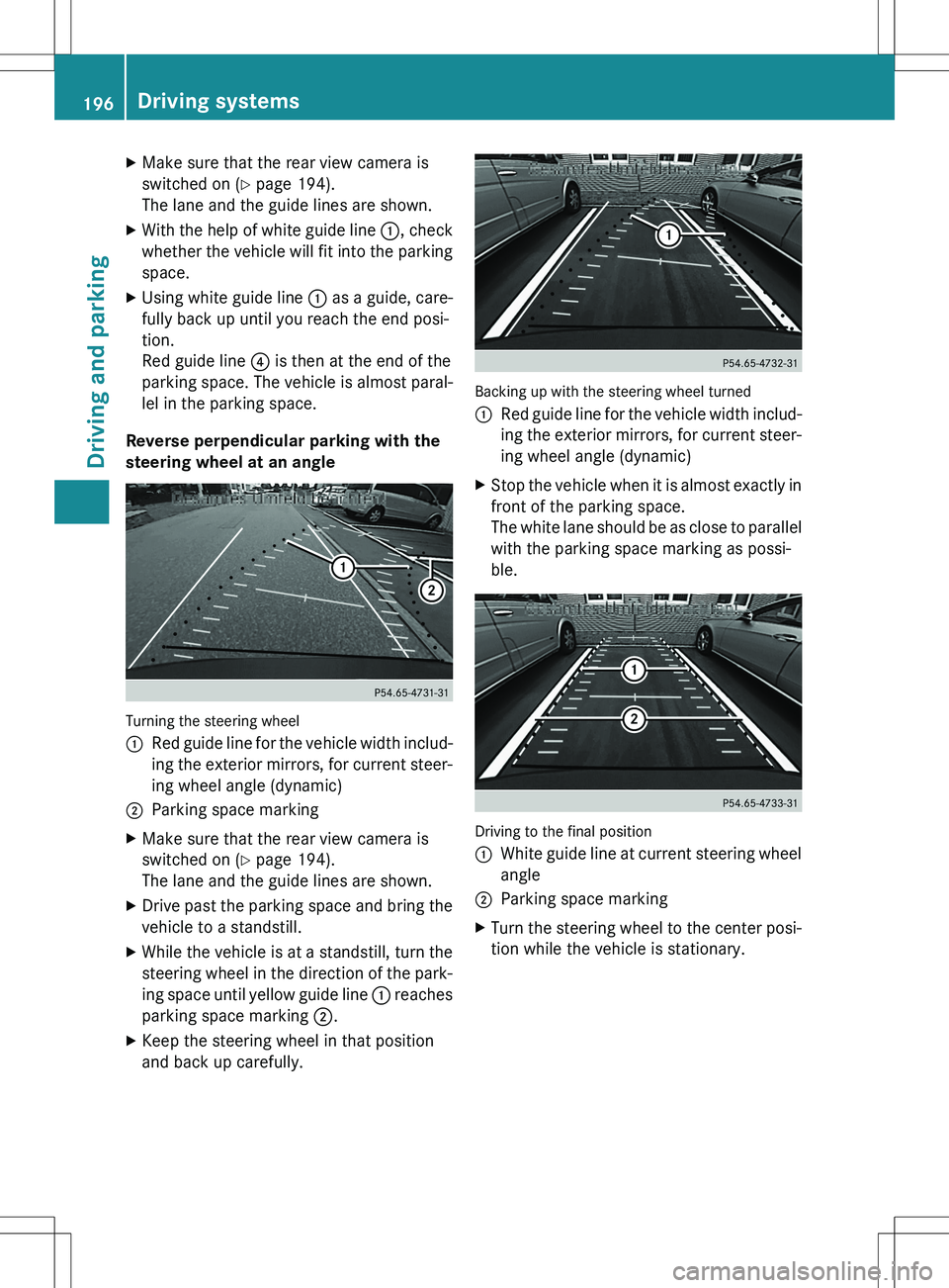
XMake sure that the rear view camera is
switched on ( Y page 194).
The lane and the guide lines are shown.
X With the help of white guide line :, check
whether the vehicle will fit into the parking space.
X Using white guide line : as a guide, care-
fully back up until you reach the end posi-
tion.
Red guide line ? is then at the end of the
parking space. The vehicle is almost paral-
lel in the parking space.
Reverse perpendicular parking with the
steering wheel at an angle
Turning the steering wheel :
Red guide line for the vehicle width includ-
ing the exterior mirrors, for current steer-
ing wheel angle (dynamic)
;Parking space marking
X Make sure that the rear view camera is
switched on ( Y page 194).
The lane and the guide lines are shown.
X Drive past the parking space and bring the
vehicle to a standstill.
X While the vehicle is at a standstill, turn the
steering wheel in the direction of the park-
ing space until yellow guide line : reaches
parking space marking ;.
X Keep the steering wheel in that position
and back up carefully.
Backing up with the steering wheel turned :
Red guide line for the vehicle width includ-
ing the exterior mirrors, for current steer-
ing wheel angle (dynamic)
X Stop the vehicle when it is almost exactly in
front of the parking space.
The white lane should be as close to parallel
with the parking space marking as possi-
ble.
Driving to the final position :
White guide line at current steering wheel
angle
;Parking space marking
X Turn the steering wheel to the center posi-
tion while the vehicle is stationary.
196Driving systems
Driving and parking
Page 202 of 386
XTo switch to full screen mode: select
Full Screen by turning cVd the
COMAND controller and press W to con-
firm.
Displays in the COMAND display
Important safety notes
! Objects not at ground level may appear to
be further away than they actually are, e.g.: R the bumper of a parked vehicle
R the drawbar of a trailer
R the ball coupling of a trailer tow hitch
R the rear section of an HGV
R a slanted post
Use the guidelines only for orientation.
Approach objects no further than the bot-
tom-most guideline.
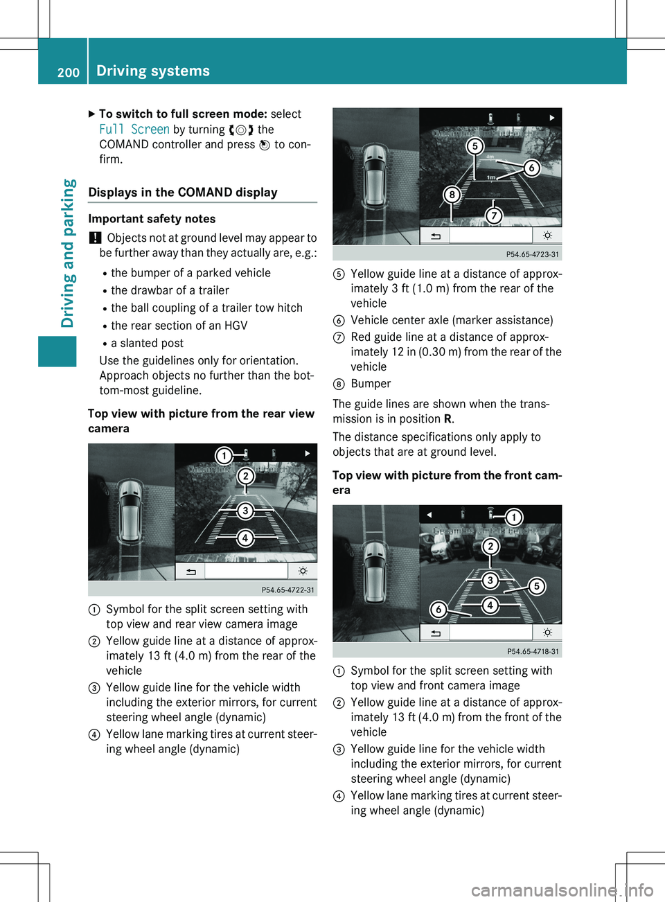
Top view with picture from the rear view
camera
:Symbol for the split screen setting with
top view and rear view camera image
;Yellow guide line at a distance of approx-
imately 13 ft (4.0 m) from the rear of the
vehicle
=Yellow guide line for the vehicle width
including the exterior mirrors, for current
steering wheel angle (dynamic)
?Yellow lane marking tires at current steer-
ing wheel angle (dynamic)
AYellow guide line at a distance of approx-
imately 3 ft (1.0 m) from the rear of the
vehicle
BVehicle center axle (marker assistance)
CRed guide line at a distance of approx-
imately 12 in (0.30 m) from the rear of the
vehicle
DBumper
The guide lines are shown when the trans-
mission is in position R.
The distance specifications only apply to
objects that are at ground level.
Top view with picture from the front cam- era
:Symbol for the split screen setting with
top view and front camera image
;Yellow guide line at a distance of approx-
imately 13 ft (4.0 m) from the front of the
vehicle
=Yellow guide line for the vehicle width
including the exterior mirrors, for current
steering wheel angle (dynamic)
?Yellow lane marking tires at current steer-
ing wheel angle (dynamic)
200Driving systems
Driving and parking
Page 203 of 386
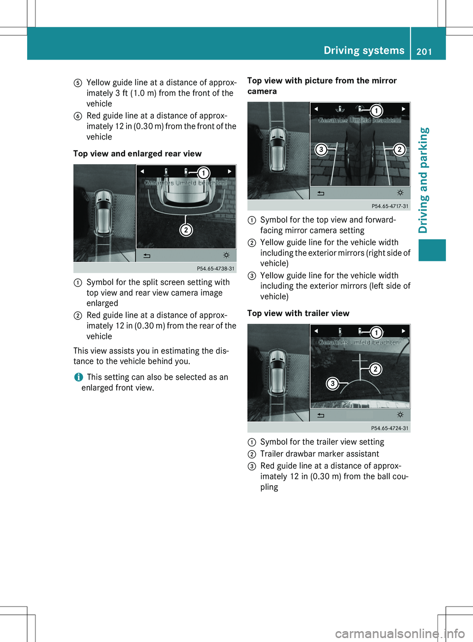
AYellow guide line at a distance of approx-
imately 3 ft (1.0 m) from the front of the
vehicle
BRed guide line at a distance of approx-
imately 12 in (0.30 m) from the front of the
vehicle
Top view and enlarged rear view
:Symbol for the split screen setting with
top view and rear view camera image
enlarged
;Red guide line at a distance of approx-
imately 12 in (0.30 m) from the rear of the vehicle
This view assists you in estimating the dis-
tance to the vehicle behind you.
iThis setting can also be selected as an
enlarged front view. Top view with picture from the mirror
camera
:Symbol for the top view and forward-
facing mirror camera setting
;Yellow guide line for the vehicle width
including the exterior mirrors (right side of
vehicle)
=Yellow guide line for the vehicle width
including the exterior mirrors (left side of
vehicle)
Top view with trailer view
:Symbol for the trailer view setting
;Trailer drawbar marker assistant
=Red guide line at a distance of approx-
imately 12 in (0.30 m) from the ball cou-
pling
Driving systems201
Driving and parking
Z
Page 216 of 386

When towing a trailer, your vehicle's handling
characteristics will be different in comparison with when driving without a trailer.
Use the left-hand paddle shifter to shift into a
lower gear in good time on long and steep
downhill gradients.
iThis also applies if you have activated
cruise control.
This will use the braking effect of the engine,
so that less braking will be required to main-
tain the speed. This relieves the load on the
brake system and prevents the brakes from
overheating and wearing too quickly. If you
need additional braking, depress the brake
pedal repeatedly rather than continuously.
Driving tips
R Maintain a greater distance from the vehi-
cle in front than when driving without a
trailer.
R Avoid braking abruptly. If possible, brake
gently at first to allow the trailer to run on.
Then, increase the braking force rapidly.
R The values given for gradient-climbing
capabilities from a standstill refer to sea
level. When driving in mountainous areas,
note that the power output of the engine
and, consequently, the vehicle's gradient-
climbing capability, decreases with
increasing altitude.
If the trailer swings from side to side:
X Do not accelerate.
X Do not counter-steer.
X Brake if necessary.
Installing the ball coupling
GWARNING
If the ball coupling is not installed and secured
correctly the trailer may come loose. There is
a risk of an accident.
Install and secure the ball coupling as descri-
bed in the ball coupling installation instruc-
tions. Make sure that the ball coupling is
installed and secured correctly before every
journey.
! Mercedes-Benz recommends that you
only use ball couplings that have been tes- ted and approved by Mercedes-Benz. This
helps to avoid damage to the vehicle.
Cover cap
X Pull protective cap : in the direction of the
arrow, out of ball coupling recess ;.
X Store protective cap : in a safe place.
X Observe the manufacturer's installation
instructions.
GWARNING
If the ball coupling is not correctly installed
and secured, it could come loose while driving
and endanger other road users. There is a risk
of an accident and injury.
Install and secure the ball coupling as descri-
bed in the ball coupling manufacturer's instal- lation instructions. Make sure that the ball
coupling is correctly installed and secured
before every journey.
Coupling up a trailer
Observe the maximum permissible trailer
dimensions (width and length).
Most U.S. states and all Canadian provinces
require by law:
R safety chains between the towing vehicle
and the trailer. The chains should be cross-
wound under the trailer drawbar. They must
214Towing a trailer
Driving and parking