2015 MERCEDES-BENZ GLE SUV mirror
[x] Cancel search: mirrorPage 299 of 453
Selecting the departure time or deactivat-
ing a selected departure time
X Press the =or; button on the steering
wheel to select the Settings
Settingsmenu.
X Press the :or9 button to select the
Heating
Heating submenu.
X Press ato confirm.
You will see the selected setting.
X Press ato confirm.
X Press the :or9 button to select one
of the three departure times or Timer
Timer off
off(no
timer active).
X Press ato confirm.
If a departure time is selected, the yellow
indicator lamp lights up on the auxiliary heat- ing button.
Changing the departure time
X Press the =or; button on the steering
wheel to select the Settings
Settings menu.
X Press the :or9 button to select the
Heating Heating submenu.
X Press ato confirm.
You will see the selected setting.
X Press the :or9 button to select A
A,B
B
or Change C
Change C.
X Press ato confirm.
You can now change the departure time.
X Press the =or; button to select the
display to be changed: hours, minutes.
X Press the :or9 button to set the
selected display.
X Press the abutton to store the entry.
The yellow indicator lamp on the auxiliary
heating button lights up.
Convenience submenu Activating/deactivating the EASY-
ENTRY/EXIT feature G
WARNING
When the EASY-ENTRY/EXIT feature adjusts
the steering wheel, you and other vehicle
occupants – particularly children – could
become trapped. There is a risk of injury.
While the EASY-ENTRY/EXIT feature is mak-
ing adjustments, make sure that no one has
any body parts in the sweep of the steering
wheel. If someone is trapped:
R press one of the memory function position
buttons, or
R move the switch for steering wheel adjust-
ment in the opposite direction to that in
which the steering wheel is moving.
The adjustment process is stopped.
X Press the =or; button on the steering
wheel to select the Settings Settingsmenu.
X Press the :or9 button to select the
Convenience
Convenience submenu.
X Press ato confirm.
X Using :or9, select the Easy
EasyEntry/
Entry/
Exit
Exit function.
If the Easy
Easy Entry/Exit
Entry/Exit function is activated,
the vehicle steering wheel is displayed in
orange in the multifunction display.
X Press the abutton to save the setting.
Further information on the EASY-ENTRY/EXIT
feature (Y page 116).
Switching belt adjustment on/off
X Press the =or; button on the steering
wheel to select the Settings Settingsmenu.
X Press the :or9 button to select the
Convenience
Convenience submenu.
X Press ato confirm.
X Press the :or9 button to select the
Belt adjustment
Belt adjustment function.
If the Belt
Belt adjustment
adjustment function is activated,
the vehicle seat belt is shown in orange in the multifunction display.
X Press the abutton to save the setting.
For further information on belt adjustment, see
(Y page 47).
Switching the fold mirrors in when lock-
ing function on/off This function is only available when the vehicle is
equipped with the electrical fold-in function.
When you activate the Auto. fold-in mir‐
Auto. fold-in mir‐
rors rors function, the exterior mirrors are folded in
when the vehicle is locked. The exterior mirrors fold out automatically again as soon as you
unlock the vehicle. 296
Menus and submenusOn-board computer and displays
Page 300 of 453
X
Press the =or; button on the steering
wheel to select the Settings
Settings menu.
X Press the :or9 button to select the
Convenience
Convenience submenu.
X Press ato confirm.
X Press the :or9 button to select the
Auto. fold-in mirrors
Auto. fold-in mirrors function.
If the Auto. fold-in mirrors
Auto. fold-in mirrors function is
switched on, the multifunction display shows
the exterior mirror in orange.
X Press the abutton to save the setting. If you have switched on the
Auto. fold-in
Auto. fold-in
mirrors
mirrors function and you fold the exterior mir-
rors in using button :, they will not fold out
automatically (Y page 118).
You can then only fold out the exterior mirrors
using button :.
Resetting to factory settings X
Press the =or; button on the steering
wheel to select the Settings
Settings menu.
X Press the :or9 button to select the
Factory setting Factory setting submenu.
X Press ato confirm.
The Reset all settings?
Reset all settings? message
appears.
X Press the :or9 button to select No
Noor
Yes
Yes.
X Press the abutton to confirm the selec-
tion.
If you have selected Yes Yes, the multifunction
display shows a confirmation message.
For safety reasons, not all functions are reset:
the Limit speed (winter tyres):
Limit speed (winter tyres): function
in permanent SPEEDTRONIC can only be set in
the Vehicle Vehicle submenu. For safety reasons, the
Daytime driving
Daytime driving
lights
lights function in the Lights
Lightssubmenu is only
reset if the engine is switched off. ON&OFFROAD menu
X
Press the =or; button on the steering
wheel to select the ON&OFFROAD
ON&OFFROADmenu.
You can view the current settings of the off-road programs in the ON&OFFROAD
ON&OFFROADmenu.
R Vehicles with the Off-Road Engineering pack-
age (Y page 254)
R Vehicles without the Off-Road Engineering
package (Y page 254) AMG menu (Mercedes-AMG vehicles)
WARMUP :
Digital speedometer
; Gear indicator
= Upshift indicator
? Engine oil temperature
A Coolant temperature
B Transmission oil temperature
X Press the =or; button on the steering
wheel to select the AMG AMGmenu.
Upshift indicator: upshift indicatorUp Up=
indicates that the engine has reached the
overrevving range when in the manual drive
program.
Engine/transmission oil temperature:
when the engine and transmission are at nor-
mal operating temperature, oil tempera- Menus and submenus
297On-board computer and displays Z
Page 316 of 453
Display messages
Possible causes/consequences and
M
MSolutions Further information on the automatic front-passenger front airbag
deactivation feature (Y page 51).Lights
i Vehicles with LED light bulbs in the light clusters:
The display message for the corresponding lamp only appears when all the LEDs in the lamp have
failed. Display messages
Possible causes/consequences and
M
MSolutions b
Left cornering Left cornering
light light
orRight cor‐
Right cor‐
nering light
nering light The left or right-hand cornering light is faulty.
X Consult a qualified specialist workshop. b
Left dipped beam Left dipped beam
or
Right dipped beam
Right dipped beam The left or right-hand dipped-beam headlamp is faulty.
X Halogen headlamp: replace the bulb (Ypage 128).
X LED headlamps: consult a qualified specialist workshop. b
Trailer left tail Trailer left tail
lamp lamp
orTrailer
Trailer
right tail lamp
right tail lamp The left or right-hand trailer tail lamp is faulty.
X Consult the manufacturer's operating instructions. b
Trailer Trailer
left
leftindica‐
indica‐
tor
tor orTrailer
Trailer
right indicator right indicator The left or right-hand trailer turn signal lamp is faulty.
X
Consult the manufacturer's operating instructions. b
Trailer brake lamp Trailer brake lamp The trailer brake lamp is faulty.
X Consult the manufacturer's operating instructions. b
Rear Rear
left
leftindicator
indicator
or Rear right indi‐
Rear right indi‐
cator
cator The rear left-hand or rear right-hand turn signal is faulty.
X Consult a qualified specialist workshop. b
Front left indica‐ Front left indica‐
tor tor
orFront right
Front right
indicator
indicator The front left-hand or front right-hand turn signal is faulty.
X Halogen headlamp: replace the bulb (Ypage 128).
X LED headlamps: consult a qualified specialist workshop. b
Left mirror indica‐ Left mirror indica‐
tor tor
orRight mirror
Right mirror
indicator
indicator The turn signal in the left-hand or right-hand exterior mirror is faulty.
X Consult a qualified specialist workshop. Display
messages
313On-board computer and displays Z
Page 329 of 453
Display messages
Possible causes/consequences and
M
MSolutions Blind Spot Assist
Blind Spot Assist
currently unavaila‐ currently unavaila‐
ble ble
See
SeeOwner's
Owner's Man‐
Man‐
ual
ual orActive BlindActive Blind
Spot Assist cur‐
Spot Assist cur‐
rently unavailable rently unavailable
See Owner's Manual See Owner's Manual Blind Spot Assist or Active Blind Spot Assist is temporarily inoperative.
Possible causes:
R the radar sensor system is outside the operating temperature range
R the radar sensor system is temporarily inoperative, e.g. due to elec-
tromagnetic radiation emitted by nearby TV or radio stations or
other sources of electromagnetic radiation
The yellow 9indicator lamps also light up in the exterior mirrors.
Once the causes listed above no longer apply, the display message
goes out.
Blind Spot Assist or Active Blind Spot Assist is operational again.
If the display message does not disappear:
X Pull over and stop the vehicle safely as soon as possible, paying
attention to road and traffic conditions.
X Safeguard the vehicle against rolling away (Y page 191).
X Restart the engine. Blind Spot Assist Blind Spot Assist
not available when not available when
towing a trailer towing a trailer
See Owner's Man‐ See Owner's Man‐
ual ual
orActive BlindActive Blind
Spot Assist not
Spot Assist not
available when tow‐ available when tow‐
ing a trailer See ing a trailer See
Owner's Manual Owner's Manual Blind Spot Assist or Active Blind Spot Assist is deactivated while tow-
ing a trailer.
You have established the electrical connection between the trailer and
your vehicle.
X Press aon the steering wheel to confirm the display message. Blind Spot Assist Blind Spot Assist
inoperative inoperativeorActive
Active
Blind Spot Assist
Blind Spot Assist
inoperative inoperative Blind Spot Assist or Active Blind Spot Assist is faulty.
The yellow 9indicator lamps also light up in the exterior mirrors.
X Consult a qualified specialist workshop. Park Assist cancel‐
Park Assist cancel‐
led led The driver's door is open.
X Repeat the parking gap measurement and parking process with the
driver's door closed. You inadvertently touched the multifunction steering wheel while
steering intervention was active.
X While steering intervention is active, make sure not to touch the
multifunction steering wheel. The vehicle has started to skid and ESP
®
has intervened.
X Use Active Parking Assist again later (Y page 228).Park Assist inoper‐ Park Assist inoper‐
ative ative PARKTRONIC is malfunctioning or faulty.
X Follow the instructions and helpful hints in the "Problems with
PARKTRONIC" section (Y page 228).
If the multifunction display still shows the display message: X Consult a qualified specialist workshop. 326
Display
messagesOn-board computer and displays
Page 365 of 453
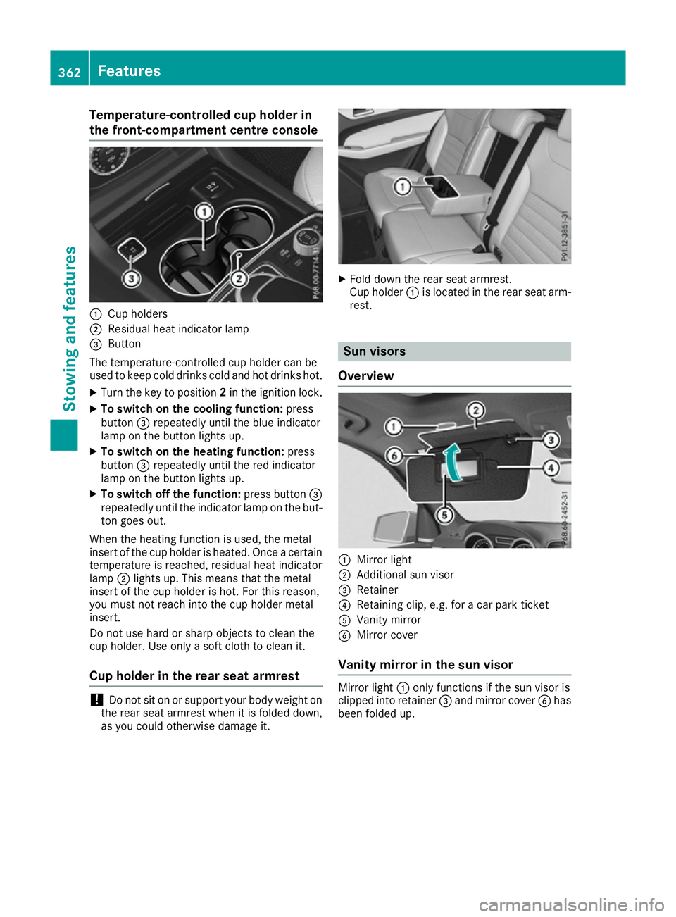
Temperature-controlled cup holder in
the front-compartment centre console :
Cup holders
; Residual heat indicator lamp
= Button
The temperature-controlled cup holder can be
used to keep cold drinks cold and hot drinks hot.
X Turn the key to position 2in the ignition lock.
X To switch on the cooling function: press
button =repeatedly until the blue indicator
lamp on the button lights up.
X To switch on the heating function: press
button =repeatedly until the red indicator
lamp on the button lights up.
X To switch off the function: press button=
repeatedly until the indicator lamp on the but-
ton goes out.
When the heating function is used, the metal
insert of the cup holder is heated. Once a certain temperature is reached, residual heat indicator
lamp ;lights up. This means that the metal
insert of the cup holder is hot. For this reason,
you must not reach into the cup holder metal
insert.
Do not use hard or sharp objects to clean the
cup holder. Use only a soft cloth to clean it.
Cup holder in the rear seat armrest !
Do not sit on or support your body weight on
the rear seat armrest when it is folded down,
as you could otherwise damage it. X
Fold down the rear seat armrest.
Cup holder :is located in the rear seat arm-
rest. Sun visors
Overview :
Mirror light
; Additional sun visor
= Retainer
? Retaining clip, e.g. for a car park ticket
A Vanity mirror
B Mirror cover
Vanity mirror in the sun visor Mirror light
:only functions if the sun visor is
clipped into retainer =and mirror cover Bhas
been folded up. 362
FeaturesSto
wing an d features
Page 370 of 453
cle. You can then no longer make calls using the
hands-free system.
If a call is active and you remove the key from
the ignition lock, the conversation is transferred over to the mobile phone. It is then possible to
continue the conversation on the mobile phone. Garage door opener
General notes The HomeLink
®
garage door opener integrated
in the rear-view mirror allows you to operate up
to three different door and gate systems.
Once programmed, the integrated garage door
opener in the rear-view mirror will assume the
function of the garage door system's remote
control. Please also read the operating instruc-
tions for the garage door system.
When programming a garage door opener, park
the vehicle outside the garage. Do not run the
engine while programming.
The garage door opener is only available for cer- tain countries. Observe the legal requirements
for each individual country.
The HomeLink ®
garage door opener is compat-
ible with most European garage and gate opener
drives. More information on HomeLink ®
and/or
compatible products is available:
R at a qualified specialist workshop
R via the HomeLink ®
Hotline
(0) 08000 466 354 65 or alternatively
+49 (0) 6838 907-277
R on the Internet at http://www.homelink.com
Important safety notes G
WARNING
When you operate or program the garage door with the integrated garage door opener, per-
sons in the range of movement of the garage
door can become trapped or struck by the
garage door. There is a risk of injury.
When using the integrated garage door
opener, always make sure that nobody is
within the range of movement of the garage
door. G
WARNING
Combustion engines emit poisonous exhaust
gases such as carbon monoxide. Inhaling
these exhaust gases leads to poisoning. There is a risk of fatal injury. Therefore never leave
the engine running in enclosed spaces with-
out sufficient ventilation.
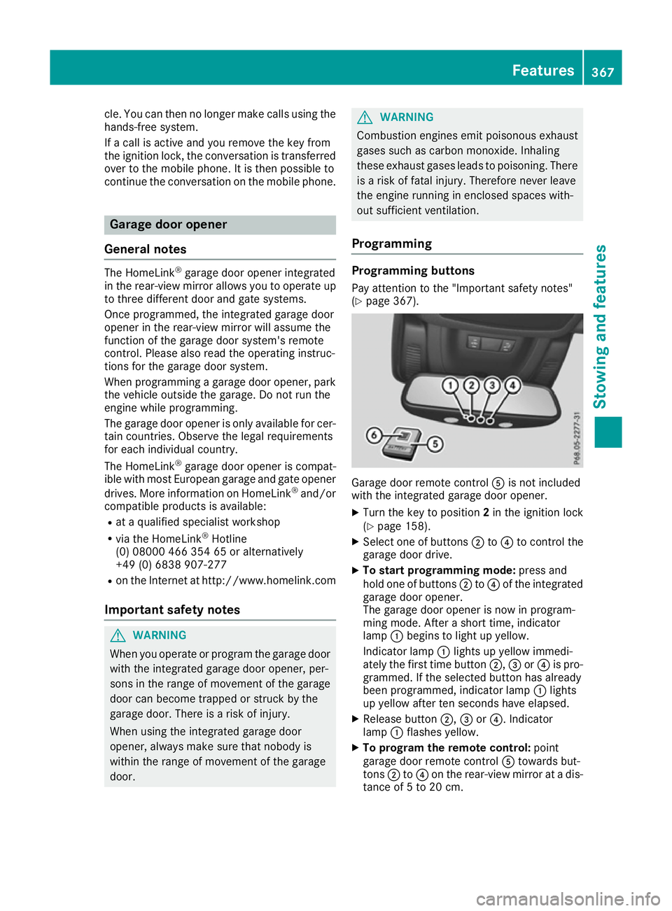
Programming Programming buttons
Pay attention to the "Important safety notes"
(Y page 367). Garage door remote control
Ais not included
with the integrated garage door opener.
X Turn the key to position 2in the ignition lock
(Y page 158).
X Select one of buttons ;to? to control the
garage door drive.
X To start programming mode: press and
hold one of buttons ;to? of the integrated
garage door opener.
The garage door opener is now in program-
ming mode. After a short time, indicator
lamp :begins to light up yellow.
Indicator lamp :lights up yellow immedi-
ately the first time button ;,=or? is pro-
grammed. If the selected button has already
been programmed, indicator lamp :lights
up yellow after ten seconds have elapsed.
X Release button ;,=or?. Indicator
lamp :flashes yellow.
X To program the remote control: point
garage door remote control Atowards but-
tons ;to? on the rear-view mirror at a dis-
tance of 5 to 20 cm. Features
367Stowing and features Z
Page 371 of 453
X
Press and hold button Bon remote control
A until indicator lamp :lights up green.
When indicator lamp :lights up green: pro-
gramming is finished.
When indicator lamp :flashes green: pro-
gramming was successful. The next step is to synchronise the rolling code (Y page 368).
X Release button Bof remote control Aof the
garage door drive.
If indicator lamp :lights up red: repeat the
programming process for the corresponding
button on the rear-view mirror. When doing
so, vary the distance between remote control A and the rear-view mirror.
The required distance between remote con-
trol Aand the integrated garage door opener
depends on the garage door drive system.
Several attempts may be required. You
should test every position for at least
25 seconds before trying another position.
Synchronising the rolling code
Observe the "Important safety notes"
(Y page 367).
If the garage door system uses a rolling code,
you will also have to synchronise the garage
door system with the integrated garage door
opener in the rear-view mirror. To do this, you
will need to use the programming button on the door drive control panel. The programming but-
ton may be placed at different locations depend- ing on the manufacturer. It is usually located on
the door drive unit on the garage ceiling.
Familiarise yourself with the garage door drive
operating instructions, e.g. under "Program-
ming of additional remote controls", before car-
rying out the following steps.
Your vehicle must be within range of the garage
door or gate opener drive. Make sure that nei-
ther your vehicle nor any persons/objects are
present within the sweep of the door or gate.
X Turn the key to position 2in the ignition lock
(Y page 158).
X Get out of the vehicle.
X Press the programming button on the door
drive unit.
Usually, you now have 30 seconds to initiate
the next step. X
Get into the vehicle.
X Press previously programmed button ;,=
or ? of the integrated garage door opener
until the door closes.
The rolling code synchronisation is then com- plete.
Problems when programming
If you have problems when programming the
integrated garage door opener, please note the following:
R Check the transmitter frequency used by
garage door drive remote control Aand
whether it is supported. The transmitter fre-
quency can usually be found on the back of
the garage door drive remote control.
R Replace the batteries in garage door remote
control A. This increases the likelihood that
garage door remote control Awill transmit a
strong and precise signal to the integrated
garage door opener in the rear-view mirror.
R When programming, hold remote control A
at varying distances and angles from the but-
ton which you are programming. Try various
angles at a distance between 5and 20 cm or
at the same angle but at varying distances.
R If there is another remote control for the same
garage door drive, perform the programming
steps again using this remote control. Before performing these steps, make sure that new
batteries have been fitted in garage door drive
remote control A.
R Note that some remote controls transmit only
for a limited period (the indicator lamp on the remote control goes out). Press button Bon
remote control Aagain before transmission
ends.
R Align the aerial cable of the garage door
opener unit. This can improve signal recep-
tion/transmission.
Opening or closing the garage door Once programmed, the integrated garage door
opener will assume the function of the garage
door system's remote control. Please also read
the operating instructions for the garage door
system. 368
FeaturesSto
wing an d features
Page 372 of 453
X
Turn the key to position 2in the ignition lock
(Y page 158).
X Press button ;,=or? which you have
programmed to operate the garage door.
Garage door system with a fixed code: indi-
cator lamp :lights up green.
Garage door system with a rolling code: indi-
cator lamp :flashes green.
The transmitter will transmit a signal for as
long as the button is pressed. The transmis-
sion is halted after a maximum of ten seconds
and indicator lamp :lights up yellow.
X Press button ;,=or? again if necessary.
Clearing the memory Make sure that you clear the memory of the
integrated garage door opener before selling the vehicle.
X Turn the key to position 2in the ignition lock
(Y page 158).
X Press and hold buttons ;and ?.
The indicator lamp initially lights up yellow
and then green.
X Release buttons ;and ?.
The memory of the integrated garage door
opener in the rear-view mirror is cleared.
Frequencies Europe
Country Radio type approval num-
ber
Frequency range (MHz)
AD (Andorra) 20 July 2005
MHz: 27, 30, 40, 433, 868
AT (Austria) Article 6 of Directive
1999/5/EC R&TTE 18 May
05
MHz: 27, 40, 433, 868
BE (Belgium) Article 6 of Directive
1999/5/EC R&TTE 18 May
05
MHz: 27, 40, 433, 868
BG (Bulgaria) Article 6 of Directive
1999/5/EC R&TTE 12 April
07
MHz: 27, 40, 433, 868 Country Radio type approval num-
ber
Frequency range (MHz)
CH (Switzer-
land) Article 6 of Directive
1999/5/EC R&TTE 14357 27
May 05
MHz: 27, 40, 433, 868 CY (Cyprus) Article 6 of Directive
1999/5/EC R&TTE 5 May 05
MHz: 27, 40, 433, 868 CZ (Czech
Republic) General Licence GL-30/R/
2000 Reg No. 844 13 May 05
MHz: 27, 40, 433 DK (Den-
mark) Article 6 of Directive
1999/5/EC R&TTE 20 April
05
MHz: 27, 40, 433, 868
DE (Ger-
many) Article 6 of Directive
1999/5/EC R&TTE 7519301
29 April 05
MHz: 27, 40, 433, 868
EE (Estonia) Article 6 of Directive
1999/5/EC R&TTE 11 May
05
MHz: 27, 40, 433, 868
ES (Spain) 000438/2005,
000439/2005,
000440/2005
000441/2005,
000445/2005,
000446/2005
000447/2005
MHz: 27, 40, 433, 868
FI (Finland) Article 6 of Directive
1999/5/EC R&TTE 10668 13
May 05
MHz: 27, 40, 433, 868 FR (France) Article 6 of Directive
1999/5/EC R&TTE 10668 13
May 05
MHz: 27, 30, 40, 433, 868 GI (Gibraltar) Article 6 of Directive
1999/5/EC R&TTE 10668 13
May 05 (UK)
MHz: 27, 40, 418, 433, 868 Features
369Stowing and features Z