2015 MERCEDES-BENZ GLE COUPE tow bar
[x] Cancel search: tow barPage 15 of 393
K
Key Changing the battery ...................... .81
Checking the battery ...................... .81
Convenience closing feature ............ 94
Convenience opening feature .......... 93
Display message ............................ 285
Door central locking/unlocking ...... .79
Emergency key element ................... 80
Important safety note s.................... 78
KEYLESS-GO start function .............. 80
Loss ................................................. 83
Modifying the programming ............. 80
Overview .......................................... 78
Positions (ignition lock) ................. 146
Problem (malfunction) ..................... 83
Starting the engine ........................ 148
Key positions
Key ................................................ 146
Start/Stop button .......................... 146
KEYLESS-GO
Convenience closing ........................ 94
Deactivation ..................................... 79
Display message ............................ 285
Locking ............................................ 79
Start function ................................... 80
Starting the engine ........................ 148
Unlocking ......................................... 79
Kickdown
Driving tip s.................................... 157
Manual gearshifting ....................... 160
Kneebag ............................................... 44 L
Lamps see Warning and indicator lamps
Lane Keeping Assist
Activating/deactivating ................. 245
Display message ............................ 274
Function/information .................... 220
see Active Lane Keeping Assist
Lap time (RACETIMER) ...................... 250
Lashing eyelets ................................. 303
Level control (display message) ...... 273
Licence plate lamp (display mes-
sage) ................................................... 267 Light sensor (display message)
....... 268
Lights
Activating/deactivating the Intel-
ligent Light System ........................ 246
Active light function ....................... 118
Adaptive Highbeam Assist PLUS .... 119
Automatic headlamp mode ............ 115
Cornering light function ................. 118
Dipped-beam headlamp s............... 116
Driving abroad ............................... 115
Foglamps (extended range) ........... 119
Hazard warning lamps ................... 117
Headlamp flashe r........................... 117
Light switch ................................... 115
Main-beam headlamp s................... 117
Motorway mode ............................. 118
Parking lamps ................................ 116
Rear foglamp ................................. 116
Side lamps ..................................... 116
Turn signals ................................... 117
see Interior lighting
LIM indicator lamp
Cruise control ................................ 179
DISTRONIC PLUS ........................... 184
Variable SPEEDTRONIC ................. 181
Limiting the speed
see SPEEDTRONIC
Loading guidelines ............................ 299
Locking
see Central locking
Locking (doors)
Automatic ........................................ 86
Emergency locking ........................... 87
From inside (central locking but-
ton) .................................................. 85
Locking centrally
see Central locking
Locking verification signal (on-
board computer) ............................... 247
Luggage compartment enlarge-
ment
Important safety notes .................. 302
Luggage compartment floor
Important safety notes .................. 305
opening/closing ............................ 305
stowage well, under ....................... 305
Lumbar support
Adjusting (on the seat) .................. 105 12
Index
Page 202 of 393
Comfort mode
In Comfort mode, the driving characteristics of
your vehicle are more comfortable. Select this
mode if you prefer a more comfortable driving
style, but also when driving fast on straight
roads, e.g. motorways.
X Press button :repeatedly until indicator
lamps ;and =go out.
You have selected Comfort mode.
The AMG Ride Control COMFORT
AMG Ride Control COMFORT message
appears in the multifunction display. PARKTRONIC
Important safety notes PARKTRONIC is an electronic parking aid with
ultrasonic sensors. It monitors the area around
your vehicle using six sensors in the front
bumper and six sensors in the rear bumper.
PARKTRONIC indicates visually and audibly the
distance between your vehicle and an object.
PARKTRONIC is only an aid. It is not a substitute
for your attention to the immediate surround-
ings. The responsibility for safe manoeuvring
and parking remains with you. Make sure that
there are no persons, animals or objects in
range while manoeuvring and parking.
! When parking, pay particular attention to
objects above or below the sensors, such as
flower pots or trailer drawbars. PARKTRONIC does not detect such objects when they are in
the immediate vicinity of the vehicle. You
could damage the vehicle or the objects.
The sensors may not detect snow and objects which absorb ultrasonic sources.
Ultrasonic sources, such as an automatic car
wash, a lorry's compressed-air brakes or a
pneumatic drill, could cause PARKTRONIC to
malfunction.
PARKTRONIC may not function correctly on
uneven terrain.
! Fold in the ball coupling if the trailer tow
hitch is not required. PARKTRONIC measures the minimum detection range to an obstacle
from the bumper, not the ball coupling.
PARKTRONIC is deactivated for the rear area
when you establish an electrical connection
between your vehicle and a trailer. PARKTRONIC is activated automatically when
you:
R switch on the ignition
R shift the transmission to position D,Ror N
R release the electric parking brake
PARKTRONIC is deactivated at speeds above
18 km/h. It is reactivated at lower speeds.
Range of the sensors General notes
PARKTRONIC does not take into account obsta-
cles located:
R below the detection range, e.g. persons, ani-
mals or objects
R above the detection range, e.g. overhanging
loads, tail sections or loading ramps of goods
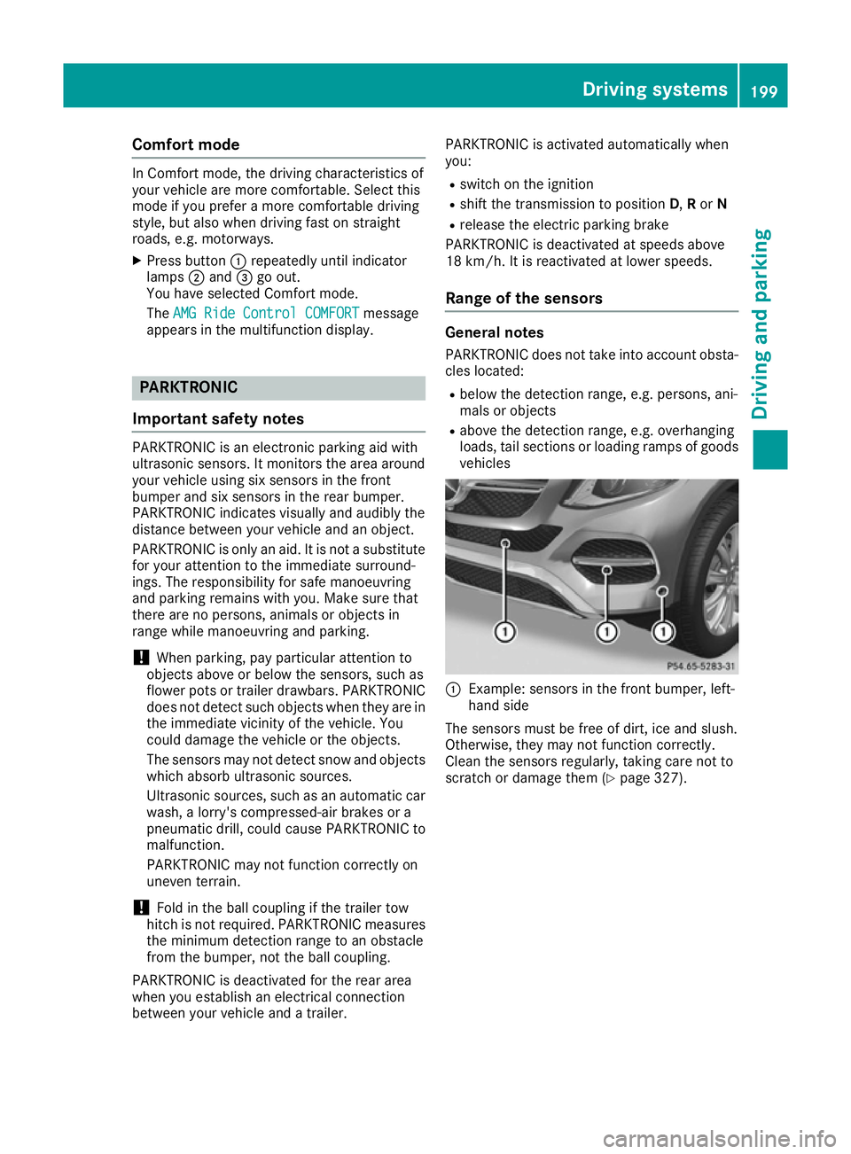
vehicles :
Example: sensors in the front bumper, left-
hand side
The sensors must be free of dirt, ice and slush.
Otherwise, they may not function correctly.
Clean the sensors regularly, taking care not to
scratch or damage them (Y page 327). Driving systems
199Driving and parking Z
Page 210 of 393
The emblem closes again when:
R you have finished the manoeuvring process
R you switch off the engine
R you open the boot
See the notes on cleaning (Y page 328).
For technical reasons, the emblem may
remain open briefly after the reversing cam-
era has been deactivated.
Activating/deactivating the reversing
camera X
To activate: make sure that the key is in
position 2in the ignition lock.
X Make sure that the Activation by R gear
Activation by R gear
function is selected in the multimedia system; see the Digital Owner's Manual.
X Engage reverse gear.
The reversing camera flap opens. The multi-
media system shows the area behind the vehi-
cle with guide lines.
The image from the reversing camera is avail-
able throughout the manoeuvring process.
X To switch the function mode for vehicles
with trailer tow hitch: using the controller,
select symbol :for the "Reverse parking"
function or symbol ;for "Coupling up a
trailer".
The symbol of the selected function is high-
lighted.
To deactivate: the reversing camera deacti-
vates if you shift the transmission to Por after
driving forwards a short distance. Displays in the multimedia system The reversing camera may show a distorted view
of obstacles or show them incorrectly or not at
all. Obstacles are not shown by the reversing
camera in the following locations:
R very close to the rear bumper
R under the rear bumper
R in the area immediately above the tailgate
handle
! Objects not at ground level may appear to
be further away than they actually are, e.g.:
R the bumper of a parked vehicle
R the drawbar of a trailer
R the ball coupling of a trailer tow hitch
R the rear section of an HGV
R a slanted post
Use the guidelines only for orientation.
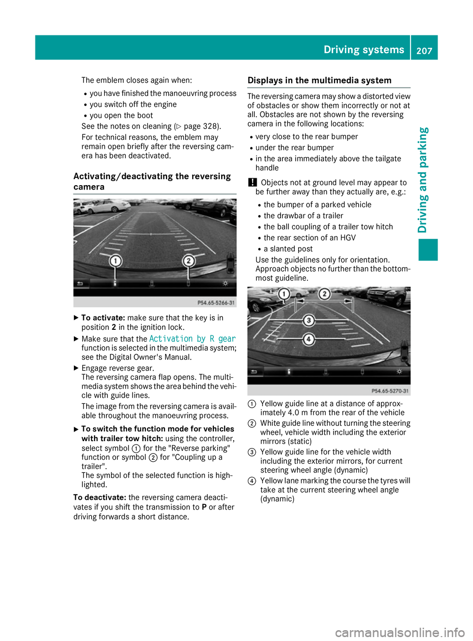
Approach objects no further than the bottom- most guideline. :
Yellow guide line at a distance of approx-
imately 4.0 m from the rear of the vehicle
; White guide line without turning the steering
wheel, vehicle width including the exterior
mirrors (static)
= Yellow guide line for the vehicle width
including the exterior mirrors, for current
steering wheel angle (dynamic)
? Yellow lane marking the course the tyres will
take at the current steering wheel angle
(dynamic) Driving systems
207Driving and parking Z
Page 213 of 393
"Coupling up a trailer" function
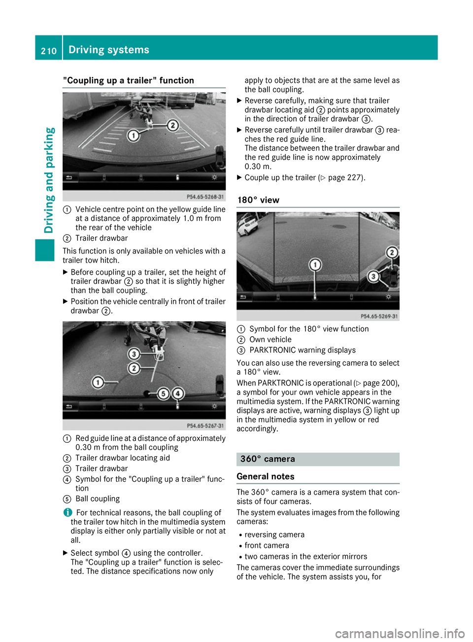
:
Vehicle centre point on the yellow guide line
at a distance of approximately 1.0 m from
the rear of the vehicle
; Trailer drawbar
This function is only available on vehicles with a
trailer tow hitch.
X Before coupling up a trailer, set the height of
trailer drawbar ;so that it is slightly higher
than the ball coupling.
X Position the vehicle centrally in front of trailer
drawbar ;. :
Red guide line at a distance of approximately
0.30 m from the ball coupling
; Trailer drawbar locating aid
= Trailer drawbar
? Symbol for the "Coupling up a trailer" func-
tion
A Ball coupling
i For technical reasons, the ball coupling of
the trailer tow hitch in the multimedia system
display is either only partially visible or not at all.
X Select symbol ?using the controller.
The "Coupling up a trailer" function is selec-
ted. The distance specifications now only apply to objects that are at the same level as
the ball coupling.
X Reverse carefully, making sure that trailer
drawbar locating aid ;points approximately
in the direction of trailer drawbar =.
X Reverse carefully until trailer drawbar =rea-
ches the red guide line.
The distance between the trailer drawbar and the red guide line is now approximately
0.30 m.
X Couple up the trailer (Y page 227).
180° view :
Symbol for the 180° view function
; Own vehicle
= PARKTRONIC warning displays
You can also use the reversing camera to select
a 180° view.
When PARKTRONIC is operational (Y page 200),
a symbol for your own vehicle appears in the
multimedia system. If the PARKTRONIC warning displays are active, warning displays =light up
in the multimedia system in yellow or red
accordingly. 360° camera
General notes The 360° camera is a camera system that con-
sists of four cameras.
The system evaluates images from the following
cameras:
R reversing camera
R front camera
R two cameras in the exterior mirrors
The cameras cover the immediate surroundings
of the vehicle. The system assists you, for 210
Driving systemsDriving and parking
Page 215 of 393
Do not use the 360° camera under such cir-
cumstances. You could otherwise injure others
or damage objects when parking the vehicle.
Guide lines are always shown at road level. In
trailer mode, the guide lines are shown at the
level of the trailer coupling.
The field of vision and other functions of the
camera system may be restricted due to addi-
tional accessories on the rear of the vehicle (e.g.
licence plate holder, bicycle rack).
On vehicles with height-adjustable suspension,
due to the technical conditions, leaving the
standard height can result in:
R inaccuracies in the guide lines
R inaccuracies in the display of generated
images (top view)
Activation conditions The 360° camera image can be displayed if:
R your vehicle is equipped with a 360° camera
R the key is in position 2in the ignition lock
R the multimedia system is switched on
Activating the 360° camera X
Press the Øbutton in the centre console
for longer than two seconds.
The following appears depending on whether transmission position Dor Ris selected:
R a split-screen with top view and the image
from the front camera or
R a split-screen with top view and the image
from the reversing camera
or
X Press the Øbutton in the centre console.
The vehicle menu appears.
X Select 360°
360° camera camera and press 7to confirm.
The following appears depending on whether transmission position Dor Ris selected:
R a split-screen with top view and the image
from the front camera or
R a split-screen with top view and the image
from the reversing camera
Switching on the 360° camera using
reverse gear You can show images from the 360° camera
automatically by engaging reverse gear. X
Make sure that the key is in position 2in the
ignition lock.
X Make sure that the Activation by R gear
Activation by R gear
function is selected in the multimedia system (see the separate operating instructions).
X To show the 360° camera image: engage
reverse gear.
The multimedia system shows the area
behind the vehicle in split-screen mode. You
see the top view of the vehicle and the image from the reversing camera.
Selecting the split-screens or 180° view Selecting split-screen view
X To switch to the line with the vehicle icons:
slide 5the controller.
X To select one of the vehicle icons: turn 3
the controller.
X To switch to 180° view
180° view :turn 3 the con-
troller to select 180° view
180° view and press7to
confirm.
i The
180° 180° view
viewoption is only available in the
following views:
R Top view with image from the reversing
camera
R Top view with image from the front camera
Displays in the multimedia system Important safety notes
The camera system may show a distorted view
of obstacles or show them incorrectly or not at
all. Obstacles are not shown by the system in the
following locations:
R under the front and rear bumpers
R very close to the front and rear bumpers
R in the area immediately above the tailgate
handle
R very close to the exterior mirrors
R in the transitional areas between the various
cameras in the virtual top view
! Objects not at ground level may appear to
be further away than they actually are, e.g.:
R the bumper of a parked vehicle
R the drawbar of a trailer
R the ball coupling of a trailer tow hitch 212
Driving systemsDriving an
d parking
Page 217 of 393
i
This setting can also be selected as an
enlarged front view.
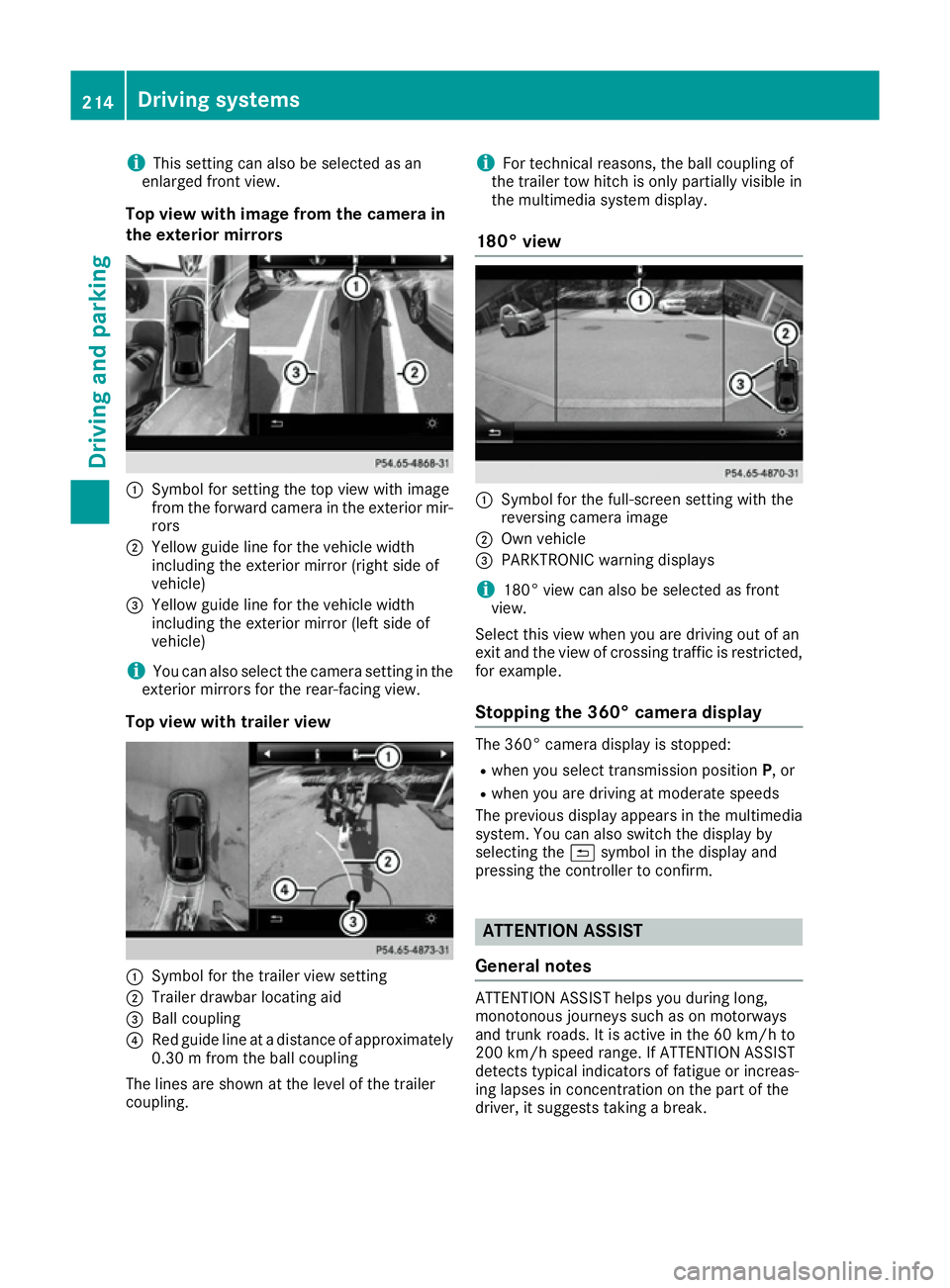
Top view with image from the camera in
the exterior mirrors :
Symbol for setting the top view with image
from the forward camera in the exterior mir-
rors
; Yellow guide line for the vehicle width
including the exterior mirror (right side of
vehicle)
= Yellow guide line for the vehicle width
including the exterior mirror (left side of
vehicle)
i You can also select the camera setting in the
exterior mirrors for the rear-facing view.
Top view with trailer view :
Symbol for the trailer view setting
; Trailer drawbar locating aid
= Ball coupling
? Red guide line at a distance of approximately
0.30 m from the ball coupling
The lines are shown at the level of the trailer
coupling. i
For technical reasons, the ball coupling of
the trailer tow hitch is only partially visible in
the multimedia system display.
180° view :
Symbol for the full-screen setting with the
reversing camera image
; Own vehicle
= PARKTRONIC warning displays
i 180° view can also be selected as front
view.
Select this view when you are driving out of an
exit and the view of crossing traffic is restricted,
for example.
Stopping the 360° camera display The 360° camera display is stopped:
R
when you select transmission position P, or
R when you are driving at moderate speeds
The previous display appears in the multimedia
system. You can also switch the display by
selecting the &symbol in the display and
pressing the controller to confirm. ATTENTION ASSIST
General notes ATTENTION ASSIST helps you during long,
monotonous journeys such as on motorways
and trunk roads. It is active in the 60 km/h to
200 km/h speed range. If ATTENTION ASSIST
detects typical indicators of fatigue or increas-
ing lapses in concentration on the part of the
driver, it suggests taking a break. 214
Driving systemsDriving an
d parking
Page 230 of 393

road users. There is a risk of an accident and
injury.
Never exceed the maximum permissible load
when using a carrier.
Exceeding the maximum permissible nose-
weight of the trailer drawbar on the ball coupling may cause damage to the following:
R your vehicle
R the trailer
R the ball coupling
R trailer tow hitch
The vehicle/trailer combination could become
unstable.
If the noseweight used is lower than the mini-
mum permissible noseweight, the vehicle/
trailer combination could also become unstable. To avoid hazardous situations:
R make sure to check the noseweight before
each journey
R use a drawbar noseweight as close as possi-
ble to the maximum noseweight
R do not exceed the maximum permissible
noseweight
R do not use a noseweight lower than the min-
imum noseweight
When reversing the vehicle towards the trailer,
make sure there is nobody between the trailer
and the vehicle.
Couple and uncouple the trailer carefully. If you
do not couple the trailer to the towing vehicle
correctly, the trailer could become detached.
Make sure that the following values are not
exceeded:
R the permissible trailer drawbar noseweight
R the permissible trailer load
R the permissible rear axle load of the towing
vehicle
R the maximum permissible gross vehicle
weight of both the towing vehicle and the
trailer
The applicable permissible values, which must
not be exceeded, can be found:
R in your vehicle documents
R on the identification plates of the trailer tow
hitch and the trailer
R on the vehicle identification plate
If the values differ, the lowest value applies. You will find the values approved by the manu-
facturer on the vehicle identification plates and those for the towing vehicle under "Technical
data" (Y page 385).
When towing a trailer, your vehicle's handling
characteristics will be different in comparison to
when driving without a trailer.
The vehicle/trailer combination:
R is heavier
R is restricted in its acceleration and gradient-
climbing capability
R has an increased braking distance
R is affected more by strong crosswinds
R demands more sensitive steering
R has a larger turning circle
This can impair the vehicle's handling charac-
teristics. Adapt your driving style accordingly.
Maintain a safe distance. Drive carefully.
When towing a trailer, always adjust your speed to the current road and weather conditions. Do
not exceed the maximum permissible speed for
your vehicle/trailer combination. Notes on towing a trailer
General notes Check the tyre pressures when towing a trailer.
You will find the values in the tyre pressure table in the vehicle fuel filler flap (Y page 351).
Please note that when towing a trailer, the fol-
lowing driving systems have limited availability
or are not available at all.
R PARKTRONIC (Y page 199)
R Blind Spot Assist (Y page 218)
R Active Lane Keeping Assist (Y page 224)
R Active Parking Assist (Y page 202)
On vehicles without level control, the height of
the ball coupling will alter according to the load
placed on the vehicle. If necessary, use a trailer
with a height-adjustable drawbar.
You will find fitting dimensions and loads under "Technical data" (Y page 384).
Driving tips Observe the information on ESP
®
trailer stabili-
sation (Y page 71) and on pulling away with a
trailer (Y page 149). Towing a trailer
227Driving and parking Z
Page 233 of 393
Vehicles with the AIRMATIC package
!
Before beginning the journey, make sure
that the trailer support wheel is completely
raised. Otherwise, the trailer or the vehicle
could be damaged by the lowered trailer sup- port wheel during the journey.
X Shift the transmission to position P.
X Apply the electric parking brake.
X Start the engine.
X Select the Comfortdrive program using the
DYNAMIC SELECT controller (Y page 195).
X Switch off the engine.
X Close the doors and tailgate.
X Position the trailer horizontally behind the
vehicle.
X Couple up the trailer.
X Establish the electrical connection between
the vehicle and the trailer.
X Check that the trailer lighting system is work-
ing.
X Push the combination switch upwards and
downwards and check whether the corre-
sponding turn signal on the trailer is flashing.
A connected trailer is only detected when the
electrical connection is established correctly
and when the lighting system is working prop-
erly. The function of other systems also depends on this, for example:
R ESP ®
R PARKTRONIC
R Active Parking Assist
R Active Blind Spot Assist
R Active Lane Keeping Assist
i Vehicles with the AIRMATIC package:
if
you couple up a trailer, the vehicle initially
remains at the selected level of the drive pro- gram set. Observe the following when cou-
pling up a trailer:
R If the normal level was not selected previ-
ously, the vehicle automatically adopts the
normal level starting from a speed of
30 km/h. Even at higher speeds, it does not drop below the normal level.
R Vehicle levels below the normal level are
not available.
R The raised level is available up to a speed of
30 km/h. R
This also applies when using accessories
that are plugged into the socket of the
trailer tow hitch (e.g. a bicycle rack).
R Before driving with a trailer, please observe
the information on the trailer support
wheel. Uncoupling a trailer
Important safety notes G
WARNING
If you uncouple a trailer with an engaged over- run brake, you could trap your hand between
the vehicle and the trailer drawbar. This poses a risk of injury.
Do not uncouple a trailer with an engaged
overrun brake. G
WARNING
Vehicles with level control:
If you disconnect the trailer cable, the vehicle is lowered. This can cause you or others to
become trapped between the vehicle body
and tyres, or underneath the vehicle. This
poses a risk of injury.
Make sure that no-one is in the immediate
vicinity of the wheel arch or underneath the
vehicle when disconnecting the trailer cable.
! Do not disconnect a trailer with an engaged
overrun brake. Otherwise, your vehicle could
be damaged by the rebounding of the overrun
brake.
! Remove the adapter cable before folding in
the ball coupling. You could otherwise dam-
age the rear bumper and the adapter cable.
Steel-sprung vehicles X
Shift the transmission to position P.
X Apply the electric parking brake.
X Secure the trailer against rolling away.
X Remove the trailer cable and decouple the
trailer. 230
Towing a trailerDriving an
d parking