2015 MERCEDES-BENZ GLE COUPE turn signal
[x] Cancel search: turn signalPage 229 of 393
R
an obstacle has been detected in the lane in
which you are driving
R a loss of tyre pressure or a defective tyre has
been detected and displayed
There is a possibility that the Active Lane Keep-
ing Assist could misjudge the given traffic sit-
uation. An inappropriate brake application may
be interrupted at any time if:
R you steer slightly in the opposite direction
R you switch on the turn signal
R you clearly brake or accelerate
A lane-correcting brake application is interrup-
ted automatically if:
R a driving safety system intervenes, such as
ESP ®
, PRE-SAFE ®
Brake or Active Blind Spot
Assist
R lane markings are no longer detected
Activating Active Lane Keeping Assist
X Activate Active Lane Keeping Assist using the
on-board computer; to do so, select Stand‐
Stand‐
ard ard orAdaptive
Adaptive (Ypage 245).
If you drive at speeds above 60 km/h and lane
markings are detected, the lines in the assis- tance graphic display (Y page 243) are
shown in green. Active Lane Keeping Assist is
ready for use.
If Standard
Standard is selected, no warning vibration
occurs if:
R you have switched on the turn signals. In
this event, the warnings are suppressed for a certain period of time.
R a driving safety system intervenes, such as
ABS, BAS or ESP ®
.
When Adaptive
Adaptive is selected, no warning vibra-
tion occurs if:
R you have switched on the turn signals. In
this event, the warnings are suppressed for
a certain period of time.
R a driving safety system intervenes, such as
ABS, BAS or ESP ®
.
R you accelerate hard, e.g. kickdown.
R you brake hard.
R you steer actively, e.g. swerve to avoid an
obstacle or change lane quickly.
R you cut the corner on a sharp bend. Towing a trailer
If you couple up a trailer, make sure that you
have correctly established the electrical con-
nection. This can be accomplished by checking
the trailer lighting. Lane-correcting brake appli-
cation does not take place when towing a trailer. Active Lane Keeping Assist is not activated and
the lines in the assistance graphic are grey. Towing a trailer
Important safety notes
G
WARNING
Vehicles with level control:
The vehicle level may be changed uninten-
tionally, e.g. by other persons. If this happens while you are coupling or decoupling a trailer,
you could become trapped. In addition, other
people could become trapped if their limbs
are between the vehicle body and the wheels or underneath the vehicle. There is a risk of
injury.
When coupling or decoupling a trailer, make
sure that no one:
R opens or closes the doors or the tailgate
R initiates a level change or turns the
DYNAMIC SELECT Controller
R locks or unlocks the vehicle G
WARNING
You could lose control of the vehicle/trailer
combination if it begins to swerve. The vehi-
cle/trailer combination could even overturn.
There is a risk of an accident.
On no account should you attempt to
straighten out the vehicle/trailer combina-
tion by increasing speed. Decrease your
speed and do not countersteer. Brake if nec-
essary. G
WARNING
If the maximum permissible load for a carrier system is exceeded, the carrier could come
loose from the vehicle and endanger other 226
Towing a trailerDriving and parking
Page 232 of 393
Until the ball coupling securely engages and
locks in a vertical position:
R indicator lamp ;flashes
R the multifunction display shows the display
message Trailer coupling extend‐
Trailer coupling extend‐
ing... ing....
The ball coupling swivels back into the out-of-
use position when:
R
R you drive off before the Trailer Trailercoupling coupling
extending...
extending... display message has disap-
peared from the multifunction display
R the ball coupling encounters an obstacle in
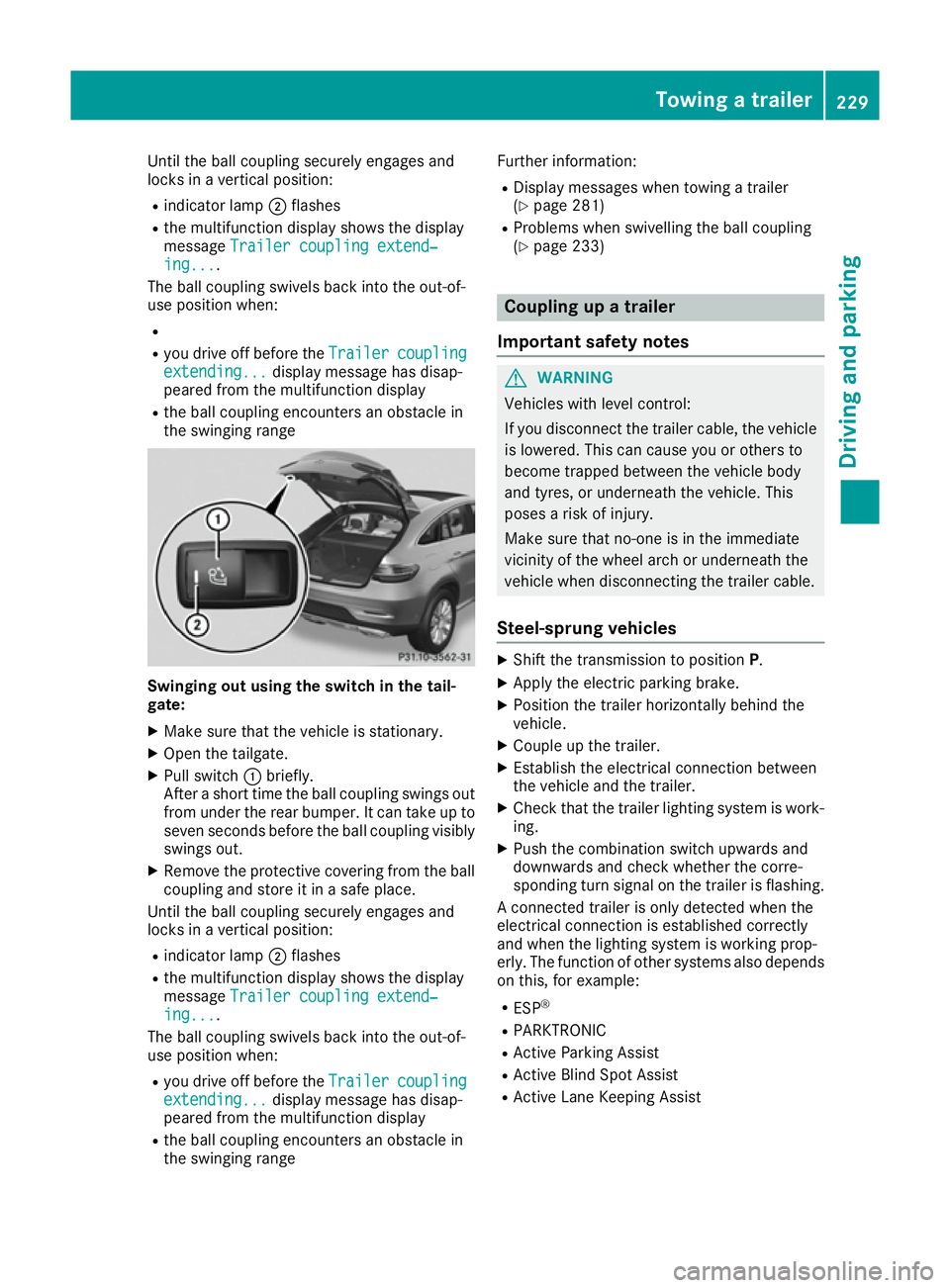
the swinging range Swinging out using the switch in the tail-
gate:
X Make sure that the vehicle is stationary.
X Open the tailgate.
X Pull switch :briefly.
After a short time the ball coupling swings out from under the rear bumper. It can take up to
seven seconds before the ball coupling visibly
swings out.
X Remove the protective covering from the ball
coupling and store it in a safe place.
Until the ball coupling securely engages and
locks in a vertical position:
R indicator lamp ;flashes
R the multifunction display shows the display
message Trailer coupling extend‐ Trailer coupling extend‐
ing...
ing....
The ball coupling swivels back into the out-of-
use position when:
R you drive off before the Trailer Trailercoupling
coupling
extending...
extending... display message has disap-
peared from the multifunction display
R the ball coupling encounters an obstacle in
the swinging range Further information:
R Display messages when towing a trailer
(Y page 281)
R Problems when swivelling the ball coupling
(Y page 233) Coupling up a trailer
Important safety notes G
WARNING
Vehicles with level control:
If you disconnect the trailer cable, the vehicle is lowered. This can cause you or others to
become trapped between the vehicle body
and tyres, or underneath the vehicle. This
poses a risk of injury.
Make sure that no-one is in the immediate
vicinity of the wheel arch or underneath the
vehicle when disconnecting the trailer cable.
Steel-sprung vehicles X
Shift the transmission to position P.
X Apply the electric parking brake.
X Position the trailer horizontally behind the
vehicle.
X Couple up the trailer.
X Establish the electrical connection between
the vehicle and the trailer.
X Check that the trailer lighting system is work-
ing.
X Push the combination switch upwards and
downwards and check whether the corre-
sponding turn signal on the trailer is flashing.
A connected trailer is only detected when the
electrical connection is established correctly
and when the lighting system is working prop-
erly. The function of other systems also depends on this, for example:
R ESP ®
R PARKTRONIC
R Active Parking Assist
R Active Blind Spot Assist
R Active Lane Keeping Assist Towing a trailer
229Driving and parking Z
Page 233 of 393
Vehicles with the AIRMATIC package
!
Before beginning the journey, make sure
that the trailer support wheel is completely
raised. Otherwise, the trailer or the vehicle
could be damaged by the lowered trailer sup- port wheel during the journey.
X Shift the transmission to position P.
X Apply the electric parking brake.
X Start the engine.
X Select the Comfortdrive program using the
DYNAMIC SELECT controller (Y page 195).
X Switch off the engine.
X Close the doors and tailgate.
X Position the trailer horizontally behind the
vehicle.
X Couple up the trailer.
X Establish the electrical connection between
the vehicle and the trailer.
X Check that the trailer lighting system is work-
ing.
X Push the combination switch upwards and
downwards and check whether the corre-
sponding turn signal on the trailer is flashing.
A connected trailer is only detected when the
electrical connection is established correctly
and when the lighting system is working prop-
erly. The function of other systems also depends on this, for example:
R ESP ®
R PARKTRONIC
R Active Parking Assist
R Active Blind Spot Assist
R Active Lane Keeping Assist
i Vehicles with the AIRMATIC package:
if
you couple up a trailer, the vehicle initially
remains at the selected level of the drive pro- gram set. Observe the following when cou-
pling up a trailer:
R If the normal level was not selected previ-
ously, the vehicle automatically adopts the
normal level starting from a speed of
30 km/h. Even at higher speeds, it does not drop below the normal level.
R Vehicle levels below the normal level are
not available.
R The raised level is available up to a speed of
30 km/h. R
This also applies when using accessories
that are plugged into the socket of the
trailer tow hitch (e.g. a bicycle rack).
R Before driving with a trailer, please observe
the information on the trailer support
wheel. Uncoupling a trailer
Important safety notes G
WARNING
If you uncouple a trailer with an engaged over- run brake, you could trap your hand between
the vehicle and the trailer drawbar. This poses a risk of injury.
Do not uncouple a trailer with an engaged
overrun brake. G
WARNING
Vehicles with level control:
If you disconnect the trailer cable, the vehicle is lowered. This can cause you or others to
become trapped between the vehicle body
and tyres, or underneath the vehicle. This
poses a risk of injury.
Make sure that no-one is in the immediate
vicinity of the wheel arch or underneath the
vehicle when disconnecting the trailer cable.
! Do not disconnect a trailer with an engaged
overrun brake. Otherwise, your vehicle could
be damaged by the rebounding of the overrun
brake.
! Remove the adapter cable before folding in
the ball coupling. You could otherwise dam-
age the rear bumper and the adapter cable.
Steel-sprung vehicles X
Shift the transmission to position P.
X Apply the electric parking brake.
X Secure the trailer against rolling away.
X Remove the trailer cable and decouple the
trailer. 230
Towing a trailerDriving an
d parking
Page 269 of 393
Display messages
Possible causes/consequences and
M
MSolutions Further information on the automatic front-passenger front airbag
deactivation feature (Y page 45).Lights
i Vehicles with LED light bulbs in the light clusters:
The display message for the corresponding lamp only appears when all the LEDs in the lamp have
failed. Display messages
Possible causes/consequences and
M
MSolutions b
Left cornering Left cornering
light light
orRight cor‐
Right cor‐
nering light
nering light The left or right-hand cornering light is faulty.
X Consult a qualified specialist workshop. b
Left dipped beam Left dipped beam
or
Right dipped beam
Right dipped beam The left or right-hand dipped-beam headlamp is faulty.
X Consult a qualified specialist workshop. b
Trailer left tail Trailer left tail
lamp lamp
orTrailer
Trailer
right tail lamp
right tail lamp The left or right-hand trailer tail lamp is faulty.
X Consult the manufacturer's operating instructions. b
Trailer Trailer
left
leftindica‐
indica‐
tor
tor orTrailer
Trailer
right indicator
right indicator The left or right-hand trailer turn signal lamp is faulty.
X
Consult the manufacturer's operating instructions. b
Trailer brake lamp Trailer brake lamp The trailer brake lamp is faulty.
X Consult the manufacturer's operating instructions. b
Rear Rear
left
leftindicator
indicator
or Rear right indi‐
Rear right indi‐
cator
cator The rear left-hand or rear right-hand turn signal is faulty.
X Consult a qualified specialist workshop. b
Front left indica‐ Front left indica‐
tor tor
orFront right
Front right
indicator indicator The front left-hand or front right-hand turn signal is faulty.
X Consult a qualified specialist workshop. b
Left mirror indica‐ Left mirror indica‐
tor tor
orRight mirror
Right mirror
indicator
indicator The turn signal in the left-hand or right-hand exterior mirror is faulty.
X Consult a qualified specialist workshop. 266
Display
messagesOn-board computer and displays
Page 289 of 393
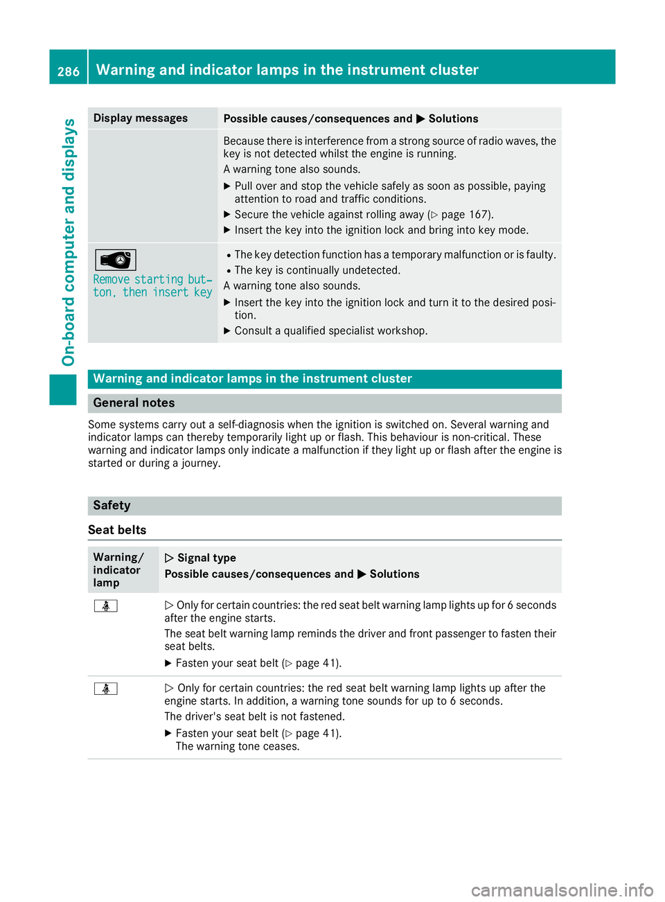
Display messages
Possible causes/consequences and
M
MSolutions Because there is interference from a strong source of radio waves, the
key is not detected whilst the engine is running.
A warning tone also sounds.
X Pull over and stop the vehicle safely as soon as possible, paying
attention to road and traffic conditions.
X Secure the vehicle against rolling away (Y page 167).
X Insert the key into the ignition lock and bring into key mode. Â
Remove Remove
starting
starting but‐
but‐
ton,
ton, then
theninsert
insert key
key R
The key detection function has a temporary malfunction or is faulty.
R The key is continually undetected.
A warning tone also sounds.
X Insert the key into the ignition lock and turn it to the desired posi-
tion.
X Consult a qualified specialist workshop. Warning and indicator lamps in the instrument cluster
General notes
Some systems carry out a self-diagnosis when the ignition is switched on. Several warning and
indicator lamps can thereby temporarily light up or flash. This behaviour is non-critical. These
warning and indicator lamps only indicate a malfunction if they light up or flash after the engine is started or during a journey. Safety
Seat belts Warning/
indicator
lamp
N N
Signal type
Possible causes/consequences and M
MSolutions ü
N
Only for certain countries: the red seat belt warning lamp lights up for 6 seconds
after the engine starts.
The seat belt warning lamp reminds the driver and front passenger to fasten their
seat belts.
X Fasten your seat belt (Y page 41).ü
N
Only for certain countries: the red seat belt warning lamp lights up after the
engine starts. In addition, a warning tone sounds for up to 6 seconds.
The driver's seat belt is not fastened.
X Fasten your seat belt (Y page 41).
The warning tone ceases. 286
Wa
rning and indi cator lamps in the instrument clusterOn-board computer and displays
Page 316 of 393
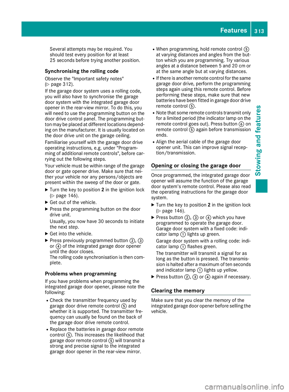
Several attempts may be required. You
should test every position for at least
25 seconds before trying another position.
Synchronising the rolling code
Observe the "Important safety notes"
(Y page 312).
If the garage door system uses a rolling code,
you will also have to synchronise the garage
door system with the integrated garage door
opener in the rear-view mirror. To do this, you
will need to use the programming button on the
door drive control panel. The programming but-
ton may be placed at different locations depend- ing on the manufacturer. It is usually located on
the door drive unit on the garage ceiling.
Familiarise yourself with the garage door drive
operating instructions, e.g. under "Program-
ming of additional remote controls", before car-
rying out the following steps.
Your vehicle must be within range of the garage
door or gate opener drive. Make sure that nei-
ther your vehicle nor any persons/objects are
present within the sweep of the door or gate.
X Turn the key to position 2in the ignition lock
(Y page 146).
X Get out of the vehicle.
X Press the programming button on the door
drive unit.
Usually, you now have 30 seconds to initiate
the next step.
X Get into the vehicle.
X Press previously programmed button ;,=
or ? of the integrated garage door opener
until the door closes.
The rolling code synchronisation is then com- plete.
Problems when programming
If you have problems when programming the
integrated garage door opener, please note the following:
R Check the transmitter frequency used by
garage door drive remote control Aand
whether it is supported. The transmitter fre-
quency can usually be found on the back of
the garage door drive remote control.
R Replace the batteries in garage door remote
control A. This increases the likelihood that
garage door remote control Awill transmit a
strong and precise signal to the integrated
garage door opener in the rear-view mirror. R
When programming, hold remote control A
at varying distances and angles from the but-
ton which you are programming. Try various
angles at a distance between 5and 20 cm or
at the same angle but at varying distances.
R If there is another remote control for the same
garage door drive, perform the programming
steps again using this remote control. Before
performing these steps, make sure that new
batteries have been fitted in garage door drive remote control A.
R Note that some remote controls transmit only
for a limited period (the indicator lamp on theremote control goes out). Press button Bon
remote control Aagain before transmission
ends.
R Align the aerial cable of the garage door
opener unit. This can improve signal recep-
tion/transmission.
Opening or closing the garage door Once programmed, the integrated garage door
opener will assume the function of the garage
door system's remote control. Please also read
the operating instructions for the garage door
system.
X Turn the key to position 2in the ignition lock
(Y page 146).
X Press button ;,=or? which you have
programmed to operate the garage door.
Garage door system with a fixed code: indi-
cator lamp :lights up green.
Garage door system with a rolling code: indi-
cator lamp :flashes green.
The transmitter will transmit a signal for as
long as the button is pressed. The transmis-
sion is halted after a maximum of ten seconds and indicator lamp :lights up yellow.
X Press button ;,=or? again if necessary.
Clearing the memory Make sure that you clear the memory of the
integrated garage door opener before selling the
vehicle. Features
313Stowing an d features Z
Page 330 of 393
vent water from draining away. This can lead
to corrosion damage and damage to elec-
tronic components.
X Clean the inside and outside of the windows
with a damp cloth and a cleaning agent that is
recommended and approved by Mercedes-
Benz.
Cleaning the wiper blades G
WARNING
If the windscreen wipers are set in motion
when cleaning the windscreen or wiper
blades, you could become trapped. There is a danger of injury.
Always switch off the windscreen wipers and
the ignition before cleaning the windscreen or wiper blades.
! Do not pull on the wiper blade. Otherwise,
the wiper blade could be damaged.
! Do not clean wiper blades too often and do
not rub them too hard. Otherwise, the graph-
ite coating could be damaged. This could
cause wiper noise.
! Hold the wiper arm securely when folding
back. The windscreen could be damaged if
the wiper arm hits against it suddenly.
X Fold the wiper arms away from the wind-
screen (Y page 122).
X Clean the wiper blades carefully using a damp
cloth.
X Fold the windscreen wipers back again before
switching on the ignition.
Cleaning the exterior lighting !
Only use cleaning agents or cleaning cloths
that are suitable for plastic lenses. Unsuitable
cleaning agents or cleaning cloths could
scratch or damage the plastic lenses of the
exterior lighting.
X Clean the plastic lenses of the exterior light-
ing using a wet sponge and a mild cleaning
agent, e. g. Mercedes-Benz car shampoo or cleaning cloths. Cleaning the mirror turn signal !
Only use cleaning agents or cleaning cloths
that are suitable for plastic lenses. Unsuitable
cleaning agents or cleaning cloths could
scratch or damage the plastic lenses of the
mirror turn signals.
X Clean the plastic lenses of the mirror turn sig-
nals in the exterior mirror housing using a wet sponge and mild cleaning agent, e.g.
Mercedes-Benz car shampoo or cleaning
cloths.
Cleaning the side running board !
Do not clean the aluminium inserts of the
side running board with alkaline or acidic
cleaners, such as wheel cleaner. Do not use
acidic wheel cleaners to remove brake dust.
The aluminium inserts could otherwise be
damaged.
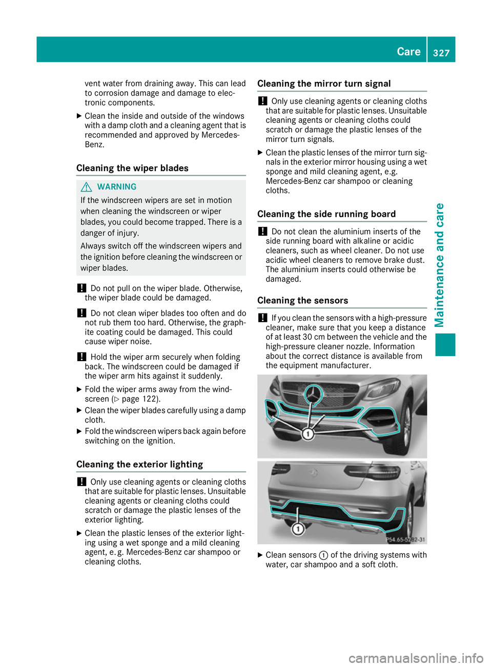
Cleaning the sensors !
If you clean the sensors with a high-pressure
cleaner, make sure that you keep a distance
of at least 30 cm between the vehicle and the
high-pressure cleaner nozzle. Information
about the correct distance is available from
the equipment manufacturer. X
Clean sensors :of the driving systems with
water, car shampoo and a soft cloth. Care
327Maintenance and care Z
Page 348 of 393
Towing the vehicle with both axles on
the ground
The automatic transmission automatically shifts to position Pwhen you open the driver's or front-
passenger door or when you remove the key
from the ignition lock.
In order to ensure that the automatic transmis-
sion stays in position Nwhen towing away the
vehicle, you must observe the following points:
X Make sure that the vehicle is stationary.
X Turn the key to position 2in the ignition lock.
X Depress the brake pedal and keep it
depressed.
X Shift the automatic transmission to position
N.
X Leave the key in position 2in the ignition lock.
X Release the brake pedal.
X Release the electric parking brake.
X Switch on the hazard warning lamps
(Y page 117).
In order to signal a change of direction when
towing the vehicle with the hazard warning
lamps switched on, use the combination switch
as usual. In this case, only the turn signals for
the desired direction flash. When you reset the
combination switch, the hazard warning lamps
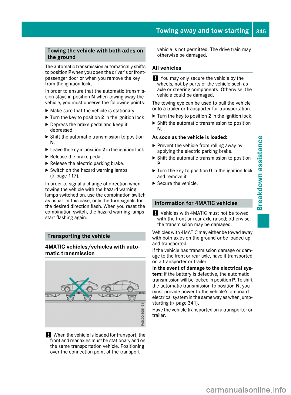
start flashing again. Transporting the vehicle
4MATIC vehicles/vehicles with auto-
matic transmission !
When the vehicle is loaded for transport, the
front and rear axles must be stationary and on
the same transportation vehicle. Positioning
over the connection point of the transport vehicle is not permitted. The drive train may
otherwise be damaged.
All vehicles !
You may only secure the vehicle by the
wheels, not by parts of the vehicle such as
axle or steering components. Otherwise, the
vehicle could be damaged.
The towing eye can be used to pull the vehicle
onto a trailer or transporter for transportation.
X Turn the key to position 2in the ignition lock.
X Shift the automatic transmission to position
N.
As soon as the vehicle is loaded:
X Prevent the vehicle from rolling away by
applying the electric parking brake.
X Shift the automatic transmission to position
P.
X Turn the key to position 0in the ignition lock
and remove it.
X Secure the vehicle. Information for 4MATIC vehicles
! Vehicles with 4MATIC must not be towed
with the front or rear axle raised; otherwise,
the transmission may be damaged.
Vehicles with 4MATIC may either be towed away
with both axles on the ground or be loaded up
and transported.
If the vehicle has transmission damage or dam- age to the front or rear axle, have it transportedon a transporter or trailer.
In the event of damage to the electrical sys-
tem: if the battery is defective, the automatic
transmission will be locked in position P. To shift
the automatic transmission to position N, you
must provide power to the vehicle's on-board
electrical system in the same way as when jump- starting (Y page 341).
Have the vehicle transported on a transporter or trailer. Towing away and tow-starting
345Breakdown assistance Z