2015 MERCEDES-BENZ GLE COUPE check engine light
[x] Cancel search: check engine lightPage 223 of 393
ted by the flashing of red warning lamp
:.
There are no further warning tones.
Activating Blind Spot Assist X Make sure that Blind Spot Assist is activated
in the on-board computer (Y page 245).
X Turn the key to position 2in the ignition lock.
Warning lamps :in the exterior mirrors light
up red for approximately 1.5 second s and
then turn yellow.
Towing a trailer
If you couple up a trailer, make sure that you
have correctly established the electrical con-
nection. This can be accomplished by checking
the trailer lighting. Blind Spot Assist is then
deactivated. The indicator lamp lights up yellow
in the exterior mirrors and the Blind Spot Blind Spot
Assist not available when towing a
Assist not available when towing a
trailer See Owner's Manual
trailer See Owner's Manual message
appears in the multifunction display.
i You can deactivate the indicator lamps in
the exterior mirrors.
To do so, you will need to deactivate Blind
Spot Assist if:
R the key is in position 2in the ignition lock
R the engine is not running
Lane Keeping Assist General notes
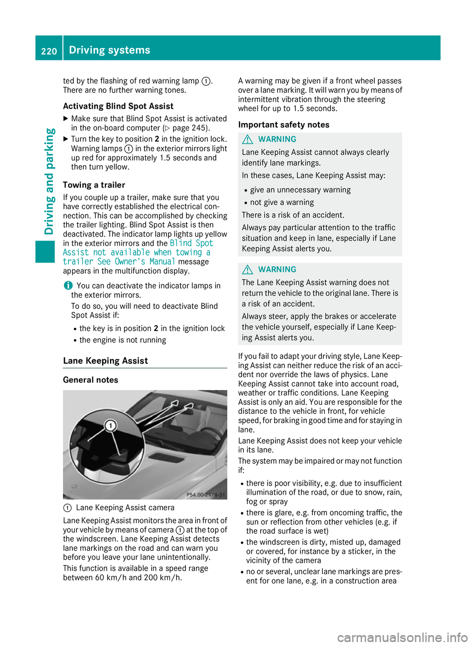
:
Lane Keeping Assist camera
Lane Keeping Assist monitors the area in front of
your vehicle by means of camera :at the top of
the windscreen. Lane Keeping Assist detects
lane markings on the road and can warn you
before you leave your lane unintentionally.
This function is available in a speed range
between 60 km/h and 200 km/h. A warning may be given if a front wheel passes
over a lane marking. It will warn you by means of
intermittent vibration through the steering
wheel for up to 1.5 second s.
Im portant safety notes G
WARNING
Lane Keeping Assist cannot always clearly
identify lane markings.
In these cases, Lane Keeping Assist may:
R give an unnecessary warning
R not give a warning
There is a risk of an accident.
Always pay particular attention to the traffic
situation and keep in lane, especially if Lane
Keeping Assist alerts you. G
WARNING
The Lane Keeping Assist warning does not
return the vehicle to the original lane. There is a risk of an accident.
Always steer, apply the brakes or accelerate
the vehicle yourself, especially if Lane Keep-
ing Assist alerts you.
If you fail to adapt your driving style, Lane Keep-
ing Assist can neither reduce the risk of an acci-
dent nor override the laws of physics. Lane
Keeping Assist cannot take into account road,
weather or traffic conditions. Lane Keeping
Assist is only an aid. You are responsible for the distance to the vehicle in front, for vehicle
speed, for braking in good time and for staying in
lane.
Lane Keeping Assist does not keep your vehicle
in its lane.
The system may be impaired or may not function if:
R there is poor visibility, e.g. due to insufficient
illumination of the road, or due to snow, rain,fog or spray
R there is glare, e.g. from oncoming traffic, the
sun or reflection from other vehicles (e.g. if
the road surface is wet)
R the windscreen is dirty, misted up, damaged
or covered, for instance by a sticker, in the
vicinity of the camera
R no or several, unclear lane markings are pres-
ent for one lane, e.g. in a construction area 220
Driving systemsDriving and parking
Page 233 of 393
Vehicles with the AIRMATIC package
!
Before beginning the journey, make sure
that the trailer support wheel is completely
raised. Otherwise, the trailer or the vehicle
could be damaged by the lowered trailer sup- port wheel during the journey.
X Shift the transmission to position P.
X Apply the electric parking brake.
X Start the engine.
X Select the Comfortdrive program using the
DYNAMIC SELECT controller (Y page 195).
X Switch off the engine.
X Close the doors and tailgate.
X Position the trailer horizontally behind the
vehicle.
X Couple up the trailer.
X Establish the electrical connection between
the vehicle and the trailer.
X Check that the trailer lighting system is work-
ing.
X Push the combination switch upwards and
downwards and check whether the corre-
sponding turn signal on the trailer is flashing.
A connected trailer is only detected when the
electrical connection is established correctly
and when the lighting system is working prop-
erly. The function of other systems also depends on this, for example:
R ESP ®
R PARKTRONIC
R Active Parking Assist
R Active Blind Spot Assist
R Active Lane Keeping Assist
i Vehicles with the AIRMATIC package:
if
you couple up a trailer, the vehicle initially
remains at the selected level of the drive pro- gram set. Observe the following when cou-
pling up a trailer:
R If the normal level was not selected previ-
ously, the vehicle automatically adopts the
normal level starting from a speed of
30 km/h. Even at higher speeds, it does not drop below the normal level.
R Vehicle levels below the normal level are
not available.
R The raised level is available up to a speed of
30 km/h. R
This also applies when using accessories
that are plugged into the socket of the
trailer tow hitch (e.g. a bicycle rack).
R Before driving with a trailer, please observe
the information on the trailer support
wheel. Uncoupling a trailer
Important safety notes G
WARNING
If you uncouple a trailer with an engaged over- run brake, you could trap your hand between
the vehicle and the trailer drawbar. This poses a risk of injury.
Do not uncouple a trailer with an engaged
overrun brake. G
WARNING
Vehicles with level control:
If you disconnect the trailer cable, the vehicle is lowered. This can cause you or others to
become trapped between the vehicle body
and tyres, or underneath the vehicle. This
poses a risk of injury.
Make sure that no-one is in the immediate
vicinity of the wheel arch or underneath the
vehicle when disconnecting the trailer cable.
! Do not disconnect a trailer with an engaged
overrun brake. Otherwise, your vehicle could
be damaged by the rebounding of the overrun
brake.
! Remove the adapter cable before folding in
the ball coupling. You could otherwise dam-
age the rear bumper and the adapter cable.
Steel-sprung vehicles X
Shift the transmission to position P.
X Apply the electric parking brake.
X Secure the trailer against rolling away.
X Remove the trailer cable and decouple the
trailer. 230
Towing a trailerDriving an
d parking
Page 238 of 393
Useful information
i This Owner's Manual describes all models,
series and optional equipment for your vehi-
cle that were available at the time of going to
press. National variations are possible. Note
that your vehicle may not be equipped with all
of the functions described. This is also the
case for systems and functions relevant to
safety.
i Read the information on qualified specialist
workshops: (Y page 25). Important safety notes
G
WARNING
Operating the integrated information systems and communications equipment in the vehicle
while driving will distract you from traffic con-
ditions. You could then lose control of the
vehicle. There is a risk of an accident.
Only operate these devices if road traffic con-
ditions permit. If you are unsure about the
surrounding conditions, pull over to a safe
location and make entries only while the vehi-
cle is stationary.
You must observe the legal requirements for the country in which you are currently driving whenoperating the on-board computer. G
WARNING
If the instrument cluster has failed or mal-
functioned, you may not recognise function
restrictions relevant to safety. The operating
safety of your vehicle may be impaired. There is a risk of an accident.
Drive on carefully. Have the vehicle checked
at a qualified specialist workshop immedi-
ately.
If the operating safety of your vehicle is
impaired, park the vehicle safely as soon as pos- sible. Contact a qualified specialist workshop.
The on-board computer only shows messages or warnings from certain systems in the multifunc-tion display. You should therefore make sure
your vehicle is operating safely at all times. For an overview, see the instrument cluster illus-
tration (Y page 29). Displays and operation
Instrument cluster lighting
The lighting in the instrument cluster, in the dis- plays and the controls in the vehicle interior can
be adjusted using the brightness control knob.
The brightness control knob is located on the
bottom left of the instrument cluster
(Y page 29).
X Turn the brightness control knob clockwise or
anti-clockwise.
If you turn the light switch to Ã,Tor
L, the brightness is dependent upon the
brightness of the ambient light.
i The light sensor in the instrument cluster
automatically controls the brightness of the
multifunction display.
In daylight, the displays in the instrument
cluster are not illuminated. Speedometer with segments
The speedometer is divided into segments only
on vehicles with DISTRONIC PLUS.
The segments in the speedometer indicate
which speed range is available.
R Variable SPEEDTRONIC activated
(Y page 180):
The segments light up from the start of the
scale to the selected limit speed.
R DISTRONIC PLUS activated (Y page 182):
One or two segments in the set speed range
light up.
R DISTRONIC PLUS detects a vehicle in front
moving more slowly than the stored speed:
The segments between the speed of the vehi- cle in front and the stored speed light up. Rev counter
! Do not drive in the overrevving range. Doing
so will damage the engine.
The red band in the rev counter indicates the
engine's overrevving range. Displays and operation
235On-board computer and displays Z
Page 262 of 393
Display messages
Possible causes/consequences and
M
MSolutions !
Parking brake inop‐ Parking brake inop‐
erative erative The yellow
!warning lamp lights up. The red !indicator lamp
flashes for about ten seconds after the electric parking brake has been applied or released. It then goes out or remains lit.
The electric parking brake is malfunctioning, e.g. because of over-
voltage or undervoltage.
X Rectify the cause of the overvoltage or undervoltage, e.g. by charg-
ing the battery or restarting the engine.
X Apply or release the electric parking brake.
If the electric parking brake still cannot be applied or released: X Switch off the ignition and turn it back on.
X Apply or release the electric parking brake.
If the electric parking brake still cannot be released: X Consult a qualified specialist workshop.
If it is still not possible to apply the electric parking brake:
X Consult a qualified specialist workshop. The yellow
!warning lamp lights up and the red !indicator
lamp flashes.
It is not possible to apply the electric parking brake manually.
X Shift the transmission to position P.
X Consult a qualified specialist workshop. J
Check brake fluid Check brake fluid
level level There is insufficient brake fluid in the brake fluid reservoir. In addition,
the J warning lamp in the instrument cluster lights up and a warn-
ing tone sounds.
G WARNING
Braking efficiency may be impaired.
There is a risk of an accident.
X Pull over and stop the vehicle safely as soon as possible, paying
attention to road and traffic conditions. Do not continue driving
under any circumstances.
X Safeguard the vehicle against rolling away (Y page 167).
X Consult a qualified specialist workshop.
X Do not top up the brake fluid. This does not correct the fault. #
Check Check
brake
brakepad
padwear
wear The brake pads/linings have reached their wear limit.
X Consult a qualified specialist workshop. G
Inoperative
Inoperative One or more main features of the Mercedes-Benz Contact system are
malfunctioning.
X Consult a qualified specialist workshop. Display
messages
259On-board computer and displays Z
Page 297 of 393
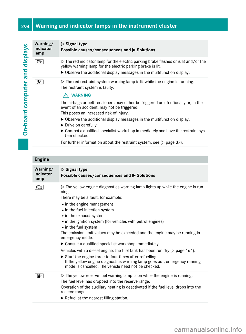
Warning/
indicator
lamp
N N
Signal type
Possible causes/consequences and M
M Solutions !
N
The red indicator lamp for the electric parking brake flashes or is lit and/or the
yellow warning lamp for the electric parking brake is lit.
X Observe the additional display messages in the multifunction display. 6
N
The red restraint system warning lamp is lit while the engine is running.
The restraint system is faulty.
G WARNING
The airbags or belt tensioners may either be triggered unintentionally or, in the
event of an accident, may not be triggered.
This poses an increased risk of injury.
X Observe the additional display messages in the multifunction display.
X Drive on carefully.
X Contact a qualified specialist workshop immediately and have the restraint sys-
tem checked.
For further information about the restraint system, see (Y page 37).Engine
Warning/
indicator
lamp
N N
Signal type
Possible causes/consequences and M
M Solutions ;
N
The yellow engine diagnostics warning lamp lights up while the engine is run-
ning.
There may be a fault, for example:
R in the engine management
R in the fuel injection system
R in the exhaust system
R in the ignition system (for vehicles with petrol engines)
R in the fuel system
The emission limit values may be exceeded and the engine may be running in
emergency mode.
X Consult a qualified specialist workshop immediately.
Vehicles with a diesel engine: the fuel tank has been run dry (Y page 164).
X Start the engine three to four times after refuelling.
If the yellow engine diagnostics warning lamp goes out, emergency running
mode is cancelled. The vehicle need not be checked. 8
N
The yellow reserve fuel warning lamp is on while the engine is running.
The fuel level has dropped into the reserve range.
Operation of the auxiliary heating is deactivated if the fuel level drops into the
reserve range.
X Refuel at the nearest filling station. 294
Warning and indicator lamps in the instrument clusterOn-board computer and displays
Page 322 of 393
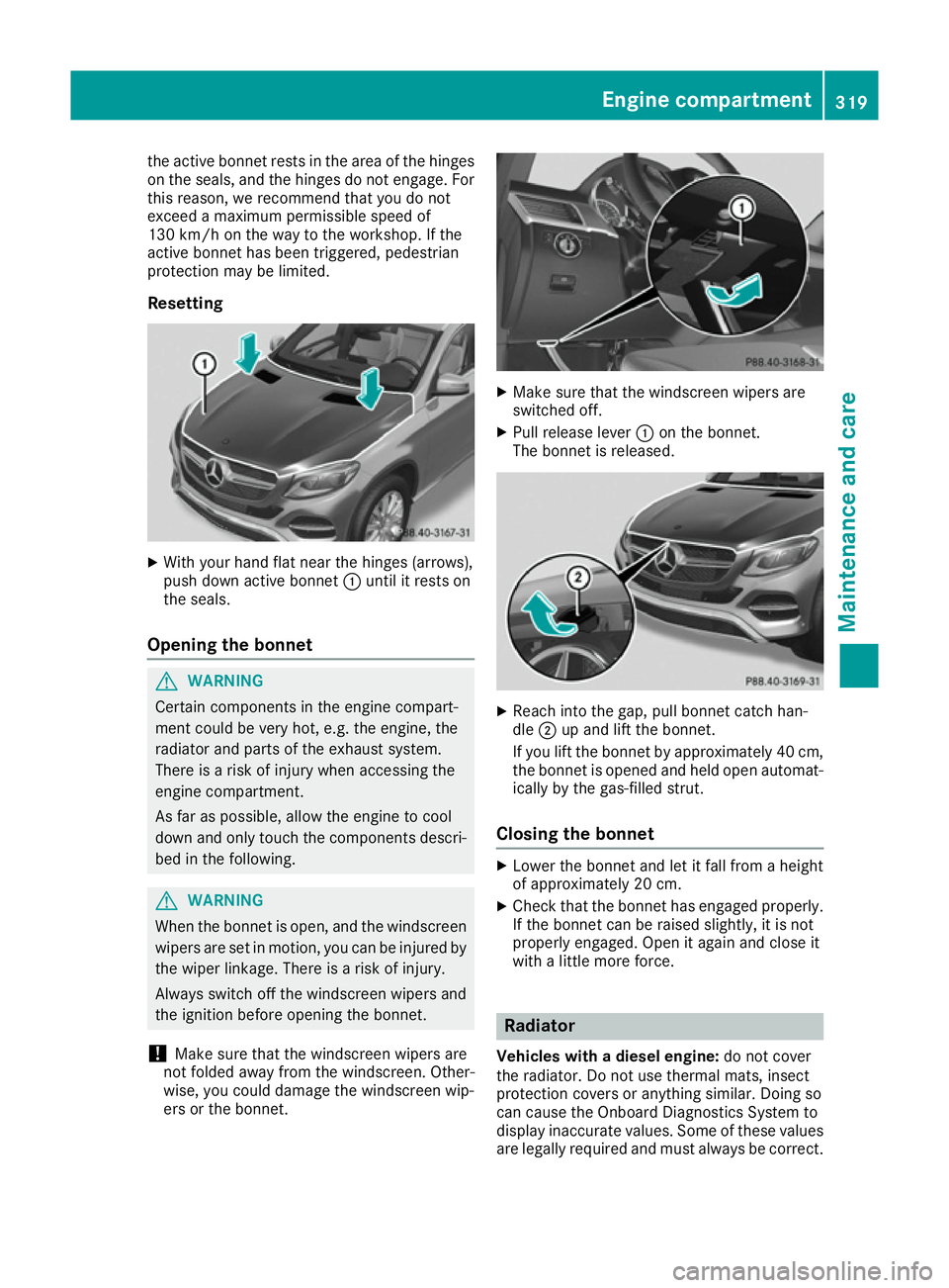
the active bonnet rests in the area of the hinges
on the seals, and the hinges do not engage. For
this reason, we recommend that you do not
exceed a maximum permissible speed of
130 km/h on the way to the workshop. If the
active bonnet has been triggered, pedestrian
protection may be limited.
Resetting X
With your hand flat near the hinges (arrows),
push down active bonnet :until it rests on
the seals.
Opening the bonnet G
WARNING
Certain components in the engine compart-
ment could be very hot, e.g. the engine, the
radiator and parts of the exhaust system.
There is a risk of injury when accessing the
engine compartment.
As far as possible, allow the engine to cool
down and only touch the components descri- bed in the following. G
WARNING
When the bonnet is open, and the windscreen wipers are set in motion, you can be injured by
the wiper linkage. There is a risk of injury.
Always switch off the windscreen wipers and
the ignition before opening the bonnet.
! Make sure that the windscreen wipers are
not folded away from the windscreen. Other-
wise, you could damage the windscreen wip-
ers or the bonnet. X
Make sure that the windscreen wipers are
switched off.
X Pull release lever :on the bonnet.
The bonnet is released. X
Reach into the gap, pull bonnet catch han-
dle ;up and lift the bonnet.
If you lift the bonnet by approximately 40 cm, the bonnet is opened and held open automat-
ically by the gas-filled strut.
Closing the bonnet X
Lower the bonnet and let it fall from a height
of approximately 20 cm.
X Check that the bonnet has engaged properly.
If the bonnet can be raised slightly, it is not
properly engaged. Open it again and close it
with a little more force. Radiator
Vehicles with a diesel engine: do not cover
the radiator. Do not use thermal mats, insect
protection covers or anything similar. Doing so
can cause the Onboard Diagnostics System to
display inaccurate values. Some of these values are legally required and must always be correct. Engine compartment
319Maintenance and care Z
Page 344 of 393
Jump-starting
For the jump-starting procedure, use only the jump-starting connection point, consisting of a pos- itive terminal and an earth point, in the engine compartment. G
WARNING
Battery acid is caustic. There is a risk of injury.
Avoid contact with the skin, eyes or clothing. Do not breathe in any battery gases. Do not lean over the battery. Keep the batteries out of the reach of children. Immediately rinse off battery acid
thoroughly with plenty of clean water and seek medical attention at once. G
WARNING
During charging and jump-starting, explosive gases can escape from the battery. There is a risk of an explosion.
Particularly avoid fire, naked flames, creating sparks and smoking. Ensure there is sufficient
ventilation while charging and jump-starting. Do not lean over a battery. G
WARNING
During the charging process, a battery produces hydrogen gas. If a short circuit occurs or sparks
are created, the hydrogen gas can ignite. There is a risk of an explosion.
R Make sure that the positive terminal of a connected battery does not come into contact with
vehicle parts.
R Never place metal objects or tools on a battery.
R It is important that you observe the described order of the battery terminals when connecting
and disconnecting a battery.
R When jump-starting, make sure that the battery poles with identical polarity are connected.
R It is particularly important to observe the described order when connecting and disconnecting
the jump leads.
R Never connect or disconnect the battery terminals while the engine is running. G
WARNING
A discharged battery can freeze at temperatures below freezing point. When jump-starting the
vehicle or charging the battery, gases can escape from the battery. There is a risk of an explosion.
Allow the frozen battery to thaw out before charging it or jump-starting.
! Vehicles with a petrol engine:
avoid repeated and lengthy starting attempts. Otherwise, the
non-combusted fuel may damage the catalytic converter.
If the indicator/warning lamps do not light up at low temperatures, it is very likely that the dis-
charged battery has frozen. In this case you may neither jump-start the vehicle nor charge the
battery. The service life of a battery that has been thawed may be reduced. The starting charac-
teristics may be impaired, especially at low temperatures. Have the thawed battery checked at a
qualified specialist workshop. Jump-starting
341Breakdown assistance Z