2015 MERCEDES-BENZ GLE COUPE lock
[x] Cancel search: lockPage 357 of 393
X
Press the abutton.
The tyre pressure values stored at the last
restart will continue to be monitored. Tyre pressure monitor
General notes If a tyre pressure monitor system is fitted, the
vehicle's wheels have sensors fitted that moni-
tor the tyre pressures in all four tyres. The tyre
pressure monitor warns you if the pressure
drops in one or more of the tyres. The tyre pres- sure monitor only functions if the corresponding
sensors are fitted to all wheels.
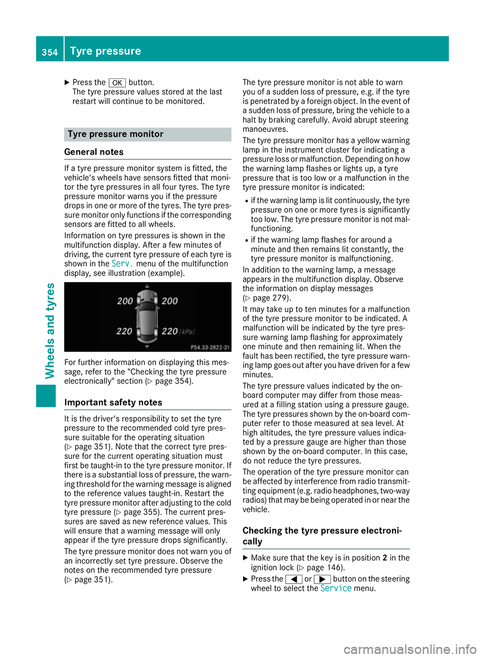
Information on tyre pressures is shown in the
multifunction display. After a few minutes of
driving, the current tyre pressure of each tyre is
shown in the Serv.
Serv. menu of the multifunction
display, see illustration (example). For further information on displaying this mes-
sage, refer to the "Checking the tyre pressure
electronically" section (Y page 354).
Important safety notes It is the driver's responsibility to set the tyre
pressure to the recommended cold tyre pres-
sure suitable for the operating situation
(Y page 351). Note that the correct tyre pres-
sure for the current operating situation must
first be taught-in to the tyre pressure monitor. If
there is a substantial loss of pressure, the warn- ing threshold for the warning message is aligned
to the reference values taught-in. Restart the
tyre pressure monitor after adjusting to the cold tyre pressure (Y page 355). The current pres-
sures are saved as new reference values. This
will ensure that a warning message will only
appear if the tyre pressure drops significantly.
The tyre pressure monitor does not warn you of
an incorrectly set tyre pressure. Observe the
notes on the recommended tyre pressure
(Y page 351). The tyre pressure monitor is not able to warn
you of a sudden loss of pressure, e.g. if the tyre is penetrated by a foreign object. In the event of
a sudden loss of pressure, bring the vehicle to a halt by braking carefully. Avoid abrupt steering
manoeuvres.
The tyre pressure monitor has a yellow warning
lamp in the instrument cluster for indicating a
pressure loss or malfunction. Depending on how
the warning lamp flashes or lights up, a tyre
pressure that is too low or a malfunction in the
tyre pressure monitor is indicated:
R if the warning lamp is lit continuously, the tyre
pressure on one or more tyres is significantly
too low. The tyre pressure monitor is not mal- functioning.
R if the warning lamp flashes for around a
minute and then remains lit constantly, the
tyre pressure monitor is malfunctioning.
In addition to the warning lamp, a message
appears in the multifunction display. Observe
the information on display messages
(Y page 279).
It may take up to ten minutes for a malfunction
of the tyre pressure monitor to be indicated. A
malfunction will be indicated by the tyre pres-
sure warning lamp flashing for approximately
one minute and then remaining lit. When the
fault has been rectified, the tyre pressure warn- ing lamp goes out after you have driven for a few
minutes.
The tyre pressure values indicated by the on-
board computer may differ from those meas-
ured at a filling station using a pressure gauge.
The tyre pressures shown by the on-board com- puter refer to those measured at sea level. At
high altitudes, the tyre pressure values indica-
ted by a pressure gauge are higher than those
shown by the on-board computer. In this case,
do not reduce the tyre pressures.
The operation of the tyre pressure monitor can
be affected by interference from radio transmit-
ting equipment (e.g. radio headphones, two-way radios) that may be being operated in or near the vehicle.
Checking the tyre pressure electroni-
cally X
Make sure that the key is in position 2in the
ignition lock (Y page 146).
X Press the =or; button on the steering
wheel to select the Service Servicemenu. 354
Tyre pressureWheels and tyres
Page 358 of 393
X
Press the 9or: button to select
Tyre pressure
Tyre pressure.
X Press the abutton.
The current tyre pressure for each wheel will
be displayed in the multifunction display.
If the vehicle has been parked for longer than
20 minutes, the Tyre pressures will be Tyre pressures will be
displayed
displayed after
aftera
afew
few minutes
minutes of
ofdriv‐
driv‐
ing
ing message appears.
After a teach-in period, the tyre pressure moni-
tor automatically detects new wheels or new
sensors. As long as a clear allocation of the tyre pressure values to the individual wheels is not
possible, the Tyre
Tyre pressure pressure monitor
monitoractive
active
display message is shown instead of the tyre
pressure display. The tyre pressures are already being monitored.
i If an emergency spare wheel is fitted, for a
few minutes the system may continue to
show the tyre pressure of the wheel that has
been removed. If this occurs, note that the
value displayed for the position where the
spare wheel is fitted is not the same as the
current tyre pressure of the emergency spare
wheel.
Warning messages of the tyre pressure monitor If the tyre pressure monitor detects a pressure
loss in one or more tyres, a warning message is
shown in the multifunction display. The yellow
tyre pressure warning lamp then lights up.
R If the Rectify tyre pressure
Rectify tyre pressure message
appears in the multifunction display, the tyre
pressure in at least one tyre is too low. The
tyre pressure must be corrected when the
opportunity arises.
R If the Check Check tyre(s)
tyre(s) message appears in the
multifunction display, the tyre pressure in at
least one tyre has dropped significantly. The
tyres must be checked.
R If the Warning tyre defect
Warning tyre defect message
appears in the multifunction display, the tyre
pressure in at least one tyre has dropped sud- denly. The tyres must be checked.
If the wheel positions on the vehicle are inter-
changed, the tyre pressures may be displayed
for the wrong positions for a short time. After a
few minutes of driving, this is rectified and the
tyre pressures are displayed for the correct
positions. Restarting the tyre pressure monitor When you restart the tyre pressure monitor, all
existing warning messages are deleted and the
warning lamps go out. The monitor uses the cur-
rently set tyre pressures as the reference values
for monitoring. In most cases, the tyre pressure monitor will automatically detect the new refer- ence values after you have changed the tyre
pressure. However, you can also set reference
values manually as described here. The tyre
pressure monitor then monitors the new tyre
pressure values.
X Use the table on the inside of the fuel filler flap
to ensure that the tyre pressure is set cor-
rectly in all four tyres for the current operating
conditions.
Also observe the notes in the section on tyre
pressures (Y page 351).
X Make sure that the key is in position 2in the
ignition lock.
X Press the =or; button on the steering
wheel to select the Serv. Serv.menu.
X Press the 9or: button to select
Tyre pressure
Tyre pressure.
X Press the abutton.
The multifunction display shows the current
tyre pressure for the individual tyres or the
Tyre pressures will be displayed Tyre pressures will be displayed
after a few minutes of driving after a few minutes of driving mes-
sage.
X Press the :button.
The Use
Use current
current pressures
pressures as
asnew
new ref‐
ref‐
erence
erence values
valuesmessage appears in the mul-
tifunction display.
If you wish to confirm the restart: X Press the abutton.
The Tyre
Tyre press.
press. monitor
monitor restarted
restarted mes-
sage appears in the multifunction display.
After you have driven for a few minutes, the
system checks whether the current tyre pres-
sures are within the specified range. The new tyre pressures are then accepted as refer-
ence values and monitored.
If you wish to cancel the restart:
X Press the %button.
The tyre pressure values stored at the last
restart will continue to be monitored. Tyre pressure
355Wheels and tyres Z
Page 360 of 393
The wear patterns on the front and rear tyres
differ depending on the operating conditions.
Interchange the wheels before a clear wear pat-
tern has formed on the tyres. Front tyres typi-
cally wear more on the shoulders and the rear
tyres in the centre.
On vehicles that have the same size front and
rear wheels, you can interchange the wheels
every 5,000 to 10,000 km depending on the
degree of tyre wear. Ensure that the direction of
rotation is maintained.
Clean the contact surfaces of the wheel and the
brake disc thoroughly every time a wheel is
interchanged. Check the tyre pressure and, if
necessary, restart the tyre pressure loss warn-
ing system or the tyre pressure monitor. Direction of rotation
Tyres with a specified direction of rotation have additional benefits, e.g. if there is a risk of aqua- planing. These advantages can only be gained if
the tyres are fitted corresponding to the direc-
tion of rotation.
An arrow on the sidewall of the tyre indicates its correct direction of rotation. Storing wheels
Store wheels that are not being used in a cool,
dry and preferably dark place. Protect the tyres
against oil, grease, petrol and diesel. Fitting a wheel
Preparing the vehicle X
Vehicles with an emergency spare wheel:
when fitting the emergency spare wheel in the
event of a flat tyre, observe the additional
notes on vehicle preparation under "Flat tyre"
(Y page 333).
X Stop the vehicle on solid, non-slippery and
level ground.
X Apply the electric parking brake manually.
X Unload heavy luggage.
X Move the front wheels to the straight-ahead
position.
X Shift the transmission to position P.X
Vehicles with the AIRMATIC package:
make sure that the normal vehicle level is
selected (Y
page 196).
X Switch off the engine.
X Vehicles without KEYLESS-GO: remove the
key from the ignition lock.
X Vehicles with KEYLESS-GO: open the driv-
er's door.
The on-board electronics now have status 0.
This is the same as the key having been
removed.
X Vehicles with KEYLESS-GO: remove the
Start/Stop button from the ignition lock
(Y page 146).
X If included in the vehicle equipment, remove
the tyre-change tool kit from the vehicle.
X Safeguard the vehicle against rolling away.
i Apart from certain country-specific varia-
tions, vehicles are not equipped with a tyre-
change tool kit. For information on which
tools are required to perform a wheel change
on your vehicle, consult a Mercedes-Benz
Service Centre.
Necessary tyre-changing tools may include,
for example:
R Jack
R Wheel chock
R Wheel wrench
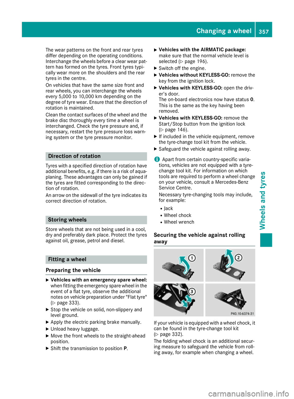
Securing the vehicle against rolling
away If your vehicle is equipped with a wheel chock, it
can be found in the tyre-change tool kit
(Y page 332).
The folding wheel chock is an additional secur-
ing measure to safeguard the vehicle from roll-
ing away, for example when changing a wheel. Changing a wheel
357Wheels and tyres Z
Page 361 of 393
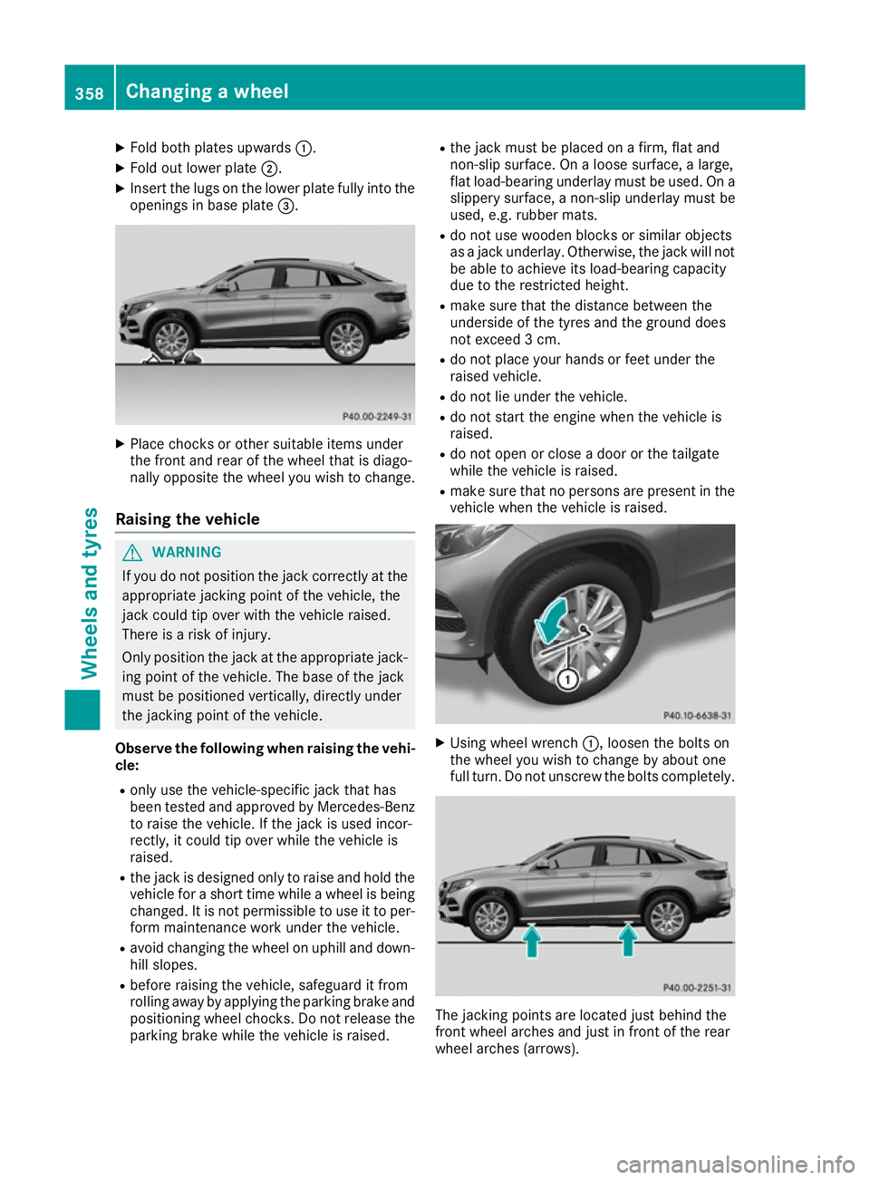
X
Fold both plates upwards :.
X Fold out lower plate ;.
X Insert the lugs on the lower plate fully into the
openings in base plate =.X
Place chocks or other suitable items under
the front and rear of the wheel that is diago-
nally opposite the wheel you wish to change.
Raising the vehicle G
WARNING
If you do not position the jack correctly at the appropriate jacking point of the vehicle, the
jack could tip over with the vehicle raised.
There is a risk of injury.
Only position the jack at the appropriate jack-
ing point of the vehicle. The base of the jack
must be positioned vertically, directly under
the jacking point of the vehicle.
Observe the following when raising the vehi- cle:
R only use the vehicle-specific jack that has
been tested and approved by Mercedes-Benz
to raise the vehicle. If the jack is used incor-
rectly, it could tip over while the vehicle is
raised.
R the jack is designed only to raise and hold the
vehicle for a short time while a wheel is being
changed. It is not permissible to use it to per- form maintenance work under the vehicle.
R avoid changing the wheel on uphill and down-
hill slopes.
R before raising the vehicle, safeguard it from
rolling away by applying the parking brake and positioning wheel chocks. Do not release theparking brake while the vehicle is raised. R
the jack must be placed on a firm, flat and
non-slip surface. On a loose surface, a large,
flat load-bearing underlay must be used. On a
slippery surface, a non-slip underlay must be
used, e.g. rubber mats.
R do not use wooden blocks or similar objects
as a jack underlay. Otherwise, the jack will not
be able to achieve its load-bearing capacity
due to the restricted height.
R make sure that the distance between the
underside of the tyres and the ground does
not exceed 3 cm.
R do not place your hands or feet under the
raised vehicle.
R do not lie under the vehicle.
R do not start the engine when the vehicle is
raised.
R do not open or close a door or the tailgate
while the vehicle is raised.
R make sure that no persons are present in the
vehicle when the vehicle is raised. X
Using wheel wrench :, loosen the bolts on
the wheel you wish to change by about one
full turn. Do not unscrew the bolts completely. The jacking points are located just behind the
front wheel arches and just in front of the rear
wheel arches (arrows).358
Changing a wheelWheels and tyres
Page 371 of 393
Vehicles with tyre pressure monitor:
after
fitting an emergency spare wheel, the system
may still display the tyre pressure of the
removed wheel for a few minutes. The value
displayed for the position where the emer-
gency spare wheel is fitted is not the same as the current tyre pressure of the emergency
spare wheel. Removing/stowing the emergency
spare wheel
Vehicles with a "Minispare" emergency
spare wheel under the luggage com-
partment floor Observe the instructions and safety notes in the
"Fitting a wheel" section (Y page 357).
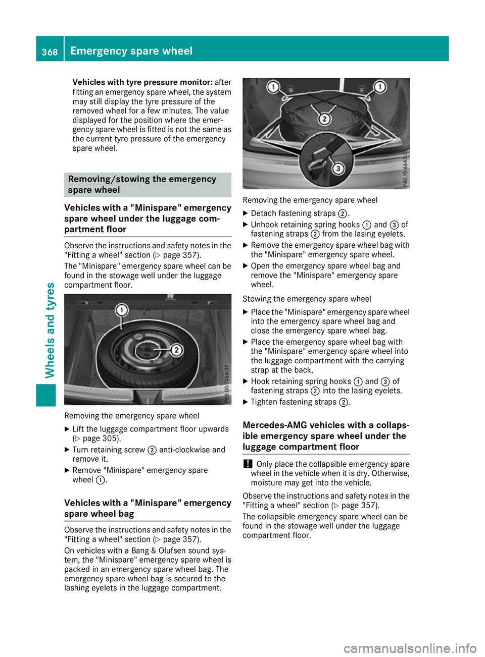
The "Minispare" emergency spare wheel can be found in the stowage well under the luggage
compartment floor. Removing the emergency spare wheel
X Lift the luggage compartment floor upwards
(Y page 305).
X Turn retaining screw ;anti-clockwise and
remove it.
X Remove "Minispare" emergency spare
wheel :.
Vehicles with a "Minispare" emergency
spare wheel bag Observe the instructions and safety notes in the
"Fitting a wheel" section (Y page 357).
On vehicles with a Bang & Olufsen sound sys-
tem, the "Minispare" emergency spare wheel is
packed in an emergency spare wheel bag. The
emergency spare wheel bag is secured to the
lashing eyelets in the luggage compartment. Removing the emergency spare wheel
X Detach fastening straps ;.
X Unhook retaining spring hooks :and =of
fastening straps ;from the lasing eyelets.
X Remove the emergency spare wheel bag with
the "Minispare" emergency spare wheel.
X Open the emergency spare wheel bag and
remove the "Minispare" emergency spare
wheel.
Stowing the emergency spare wheel
X Place the "Minispare" emergency spare wheel
into the emergency spare wheel bag and
close the emergency spare wheel bag.
X Place the emergency spare wheel bag with
the "Minispare" emergency spare wheel into
the luggage compartment with the carrying
strap at the back.
X Hook retaining spring hooks :and =of
fastening straps ;into the lasing eyelets.
X Tighten fastening straps ;.
Mercedes-AMG vehicles with a collaps-
ible emergency spare wheel under the
luggage compartment floor !
Only place the collapsible emergency spare
wheel in the vehicle when it is dry. Otherwise,
moisture may get into the vehicle.
Observe the instructions and safety notes in the
"Fitting a wheel" section (Y page 357).
The collapsible emergency spare wheel can be
found in the stowage well under the luggage
compartment floor. 368
Emergency spare wheelWheels and tyres
Page 372 of 393
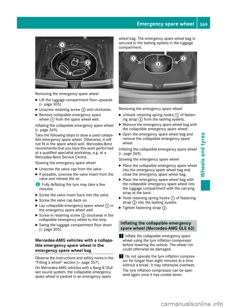
Removing the emergency spare wheel
X Lift the luggage compartment floor upwards
(Y page 305).
X Unscrew retaining screw ;anti-clockwise.
X Remove collapsible emergency spare
wheel :from the spare wheel well.
Inflating the collapsible emergency spare wheel (Y page 369).
Take the following steps to stow a used collaps-
ible emergency spare wheel. Otherwise, it will
not fit in the spare wheel well. Mercedes-Benz
recommends that you have this work performed
at a qualified specialist workshop, e.g. at a
Mercedes-Benz Service Centre.
Stowing the emergency spare wheel
X Unscrew the valve cap from the valve.
X If possible, unscrew the valve insert from the
valve and release the air.
i Fully deflating the tyre may take a few
minutes.
X Screw the valve insert back into the valve.
X Screw the valve cap back on.
X Lay collapsible emergency spare wheel :in
the emergency spare wheel well.
X Screw in retaining screw ;clockwise in the
collapsible emergency wheel to the stop.
X Swing the luggage compartment floor down
(Y page 305).
Mercedes-AMG vehicles with a collaps-
ible emergency spare wheel in the
emergency spare wheel bag Observe the instructions and safety notes in the
"Fitting a wheel" section (Y page 357).
On Mercedes-AMG vehicles with a Bang & Oluf-
sen sound system, the collapsible emergency
spare wheel is packed in an emergency spare wheel bag. The emergency spare wheel bag is
secured to the lashing eyelets in the luggage
compartment. Removing the emergency spare wheel
X Unhook retaining spring hooks :of fasten-
ing strap ;from the lashing eyelets.
X Remove the emergency spare wheel bag with
the collapsible emergency spare wheel.
X Open the emergency spare wheel bag and
remove the collapsible emergency spare
wheel.
Inflating the collapsible emergency spare wheel (Y page 369).
Stowing the emergency spare wheel
X Place the collapsible emergency spare wheel
into the emergency spare wheel bag and
close the emergency spare wheel bag.
X Place the emergency spare wheel bag with
the collapsible emergency spare wheel into
the luggage compartment with the carrying
strap at the back.
X Hook retaining spring hooks :of fastening
strap ;into the lashing eyelets.
X Tighten fastening strap ;. Inflating the collapsible emergency
spare wheel (Mercedes-AMG GLE 63)
! Inflate the collapsible emergency spare
wheel using the tyre inflation compressor
before lowering the vehicle. The wheel rim
could otherwise be damaged.
! Do not operate the tyre inflation compres-
sor for longer than eight minutes at a time
without a break. It may otherwise overheat.
The tyre inflation compressor can be oper-
ated again once it has cooled down. Emergency spare wheel
369Wheels and tyres Z
Page 373 of 393
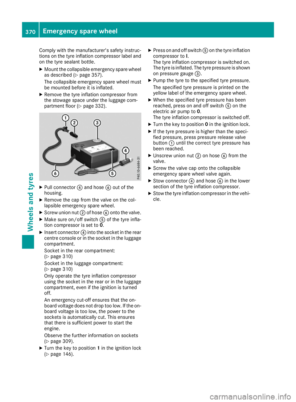
Comply with the manufacturer's safety instruc-
tions on the tyre inflation compressor label and
on the tyre sealant bottle.
X Mount the collapsible emergency spare wheel
as described (Y page 357).
The collapsible emergency spare wheel must
be mounted before it is inflated.
X Remove the tyre inflation compressor from
the stowage space under the luggage com-
partment floor (Y page 332). X
Pull connector ?and hose Bout of the
housing.
X Remove the cap from the valve on the col-
lapsible emergency spare wheel.
X Screw union nut ;of hose Bonto the valve.
X Make sure on/off switch Aof the tyre infla-
tion compressor is set to 0.
X Insert connector ?into the socket in the rear
centre console or in the socket in the luggage
compartment.
Socket in the rear compartment:
(Y page 310)
Socket in the luggage compartment:
(Y page 310)
Only operate the tyre inflation compressor
using the socket in the rear or in the luggage
compartment, even if the ignition is turned
off.
An emergency cut-off ensures that the on-
board voltage does not drop too low. If the on-
board voltage is too low, the power to the
sockets is automatically cut. This ensures
that there is sufficient power to start the
engine.
Observe the further information on sockets
(Y page 309).
X Turn the key to position 1in the ignition lock
(Y page 146). X
Press on and off switch Aon the tyre inflation
compressor to I.
The tyre inflation compressor is switched on.
The tyre is inflated. The tyre pressure is shown
on pressure gauge =.
X Pump the tyre to the specified tyre pressure.
The specified tyre pressure is printed on the
yellow label of the emergency spare wheel.
X When the specified tyre pressure has been
reached, press on and off switch Aon the
electric air pump to 0.
The tyre inflation compressor is switched off.
X Turn the key to position 0in the ignition lock.
X If the tyre pressure is higher than the speci-
fied pressure, press pressure release valve
button :until the correct tyre pressure has
been reached.
X Unscrew union nut ;on hose Bfrom the
valve.
X Screw the valve cap onto the collapsible
emergency spare wheel valve again.
X Stow connector ?and hose Bin the lower
section of the tyre inflation compressor.
X Stow the tyre inflation compressor in the vehi-
cle. 370
Emergency spare wheelWheels and tyres
Page 384 of 393
Windscreen washer system
Important safety notes G
WARNING
If windscreen washer concentrate comes into contact with hot components of the engine or
the exhaust system, it can ignite. There is a
risk of fire and injury.
Make sure the windscreen washer concen-
trate does not come into contact with the filler neck.
! Only use washer fluid that is suitable for
plastic lamp lenses, e.g. MB SummerFit or MB
WinterFit. Unsuitable washer fluid could dam-
age the plastic lenses of the headlamps.
! Only the washer fluids SummerFit and Win-
terFit can be mixed. Otherwise, the spraying
nozzles could become blocked.
Do not use distilled or de-ionised water as the
level sensor may be triggered erroneously.
When handling washer fluid, observe the impor- tant safety notes on service products
(Y page 374).
At temperatures above freezing:
X Fill the washer fluid reservoir with a mixture of
water and washer fluid, e.g. MB SummerFit.
Mix 1 part MB SummerFit to 100 parts water.
At temperatures below freezing:
X Fill the washer fluid reservoir with a mixture of
water and washer fluid, e.g. MB WinterFit.
For the correct mixing ratio refer to the infor- mation on the antifreeze reservoir.
i Add washer fluid concentrate, e.g. MB Sum-
merFit or MB WinterFit, to the washer fluid all
year round. Vehicle data
General notes
Please note that for the specified vehicle data: R the heights specified may vary as a result of:
- tyres
- load
- condition of the suspension
- optional equipment
R optional equipment reduces the maximum
payload
R vehicle-specific weight information can be
found on the vehicle identification plate
(Y page 373).
R only for certain countries: you can find vehi-
cle-specific vehicle data in the COC docu-
ments (CERTIFICATE OF CONFORMITY).
These documents are delivered with your
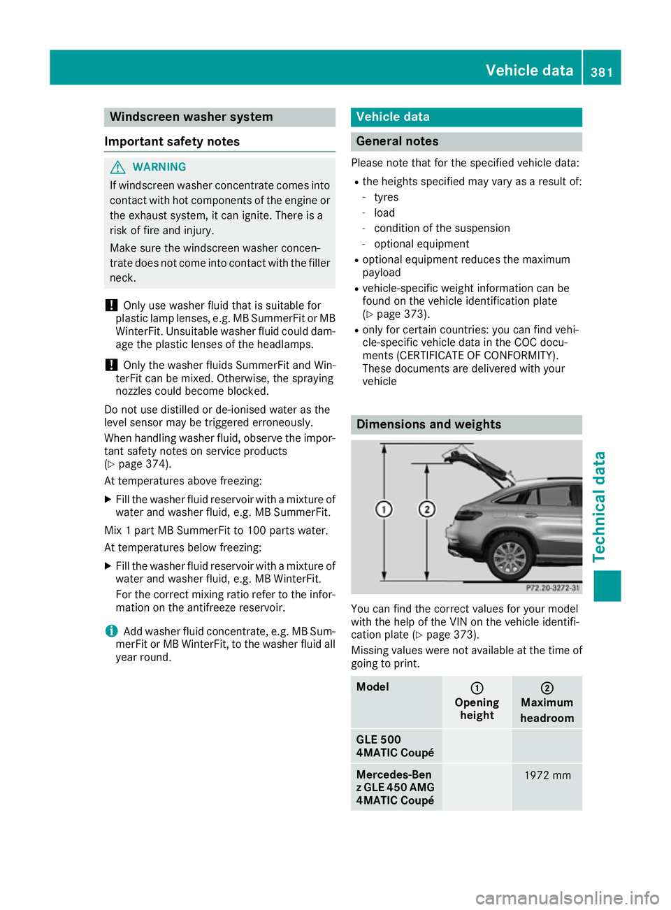
vehicle Dimensions and weights
You can find the correct values for your model
with the help of the VIN on the vehicle identifi-
cation plate (Y page 373).
Missing values were not available at the time of
going to print. Model
: :
Opening height ;
;
Maximum
headroom GLE 500
4MATIC Coupé
Mercedes‑Ben
z GLE 450 AMG
4MATIC Coupé 1972 mmVehicle data
381Technical data Z